Creating a Wardrobe detailed drawing, Floor Plan, Kitchen Layout and Column Detail using AutoCad
INTRODUCTION : Commands used for drawing the plans and drawings below are as follows :
- Line : Draw lines in AutoCAD
- Polygon : Draws polygons with three or more sides
- Rectangle : Used to draw rectangles
- Circle : Command used to draw circles
- Ellipse : Used to draw ellipse.
- Erase – Erase object in the drawing area
- Copy – Used to copy one or more objects
- Mirror – Command used to mirror an exact duplicate of an object.
- Offset – Used to offset one object from another a distance you specify
- Extend – Used to extend one line to another
- Array – Use to make a rectangular or polar array of an object
- Move – Used to move objects around in the drawing area
- Rotate – Used to rotate an object around a base point
- Scale – Command used to make an object larger or smaller
- Trim – Command used to trim an object from another object
- Chamfer – Used to put a chamfer between two lines
- Fillet – Used to put a fillet between two lines of a radius you specify, ETC.
PROBLEM-1
AIM : TO DRAW A CABINET OR WARDROPE.
STEPS :
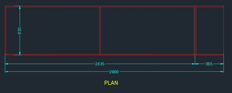
- Steps for drawing plan :
- Open Auto Cad and enter UN (units command) in command box and make the type as decimal.
- Select line command and draw a line of 2800 in X direction and a line of 630 in Y direction and complete the rectangle.
- Select offset command and give an offset of 12 on all 3 sides except right side of 630.
- Trim unwanted lines at corners by Trim command.
- Draw an offset of 2435 from right corner in X direction.
- Again draw an offset of 15 on right and left of line 2435.
- Trim the unwanted lines by trim command.
- Offset of 1223 from left line and again an offset of 6 from both sies of 1223.
- Trim the unwanted lines.
- Give the dimension to plan by Dim linear command in command box.
- Steps for drawing Front Elevation :
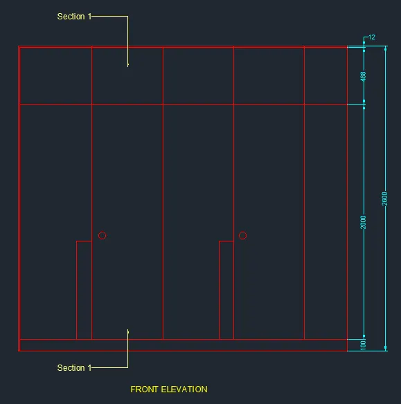
- Select line command and draw a line of 2800 in X direction and a line of 630 in Y direction and complete the rectangle.
- Draw an offset of 12 on top and left side of the figure drawn.
- Trim the left edge upper corner.
- Offset of 500 from top of cabinet and offset of 100 from bottom of cabinet.
- Trim unwanted edges and lines by trim command.
- Offset 365 from left single line of cabinet.
- Offset 1200 from left offset line in Y direction.
- Divide in two equal parts both offset line to create four panels of cabinet.
- Drawing a line of 100 hight from the middle of the cabinet at a distance of 80.
- Drawing a circle of about 30 at the point approximately at centre as a handle.
- Give the dimensions to figure.
- Steps for drawing Carcase Elevation :
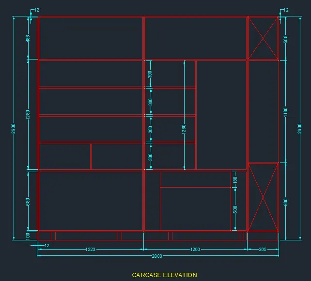
- Select line command and draw a line of 2800 in X direction and a line of 2600 in Y direction and complete the rectangle.
- Give an offset of 12 on 3 sides of the figure except right hand side.
- Trim the unwanted lines by trim command.
- Give offset of 365 from left of cabinet and again give the offset of 6 on both sides of 365 line.
- Offset 100 from bottom of cabinet
- Offset 20 below line and again offset 20 above 100 line.
- Command offset 1223 from left line to centre and offset 20 from both sides of line.
- Trim unwanted lines.
- Divide the space of 2nd part of cabinet of 1200 in two parts for the hangar space.
- Offset 900 line from bottom line of 3rd part of the cabinet.
- Offset 20 from all three sides.
- From 12mm offset line in 3rd part of cabinet draw an offset o 208mm.
- Offset 20 from left line.
- Draw legs to the cabinet in the bottom most part of 100 mm approx.
- Give dimensions to the cabinet using dim linear command.
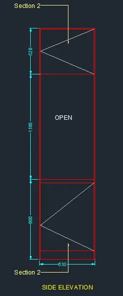
- Steps for drawing side elevation :
- Select line command and draw a line of 2800 in X direction and a line of 630 in Y direction and complete the rectangle.
- Offset 20 from all three sides except bottom of cabinet.
- Trim unwanted lines by trim command.
- Offset 100 and 900 from bottom line.
- Offset 20mm below 900 mm line offset line.
- Offset 520 from top.
- Trim unwanted lines.
- Give dimensions by Dim linear command.
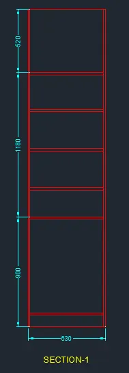
- Steps for drawing section 1 :
- Select line command and draw a line of 630 in X direction and a line of 2600 in Y direction and complete the rectangle.
- Draw an offset of 100mm from base line.
- Offset 900 from base line.
- Draw an offset of 20 mm.
- Again, give an offset of 300 and 20 mm 4 times.
- Trim unwanted lines and edges.
- Give dimensions using dimlinear command.
- Steps for drawing section 2 :
- Select line command and draw a line of 365 in X direction and a line of 2600 in Y direction and complete the rectangle.
- Extend the lines from section 1 in the diagram as desired
- Give dimensions by dimlinear command.
- Give an offset of 12 from right and bottom line and top.
- FINAL DRAWING OF CABINET :
- Drawing the layers- Select layers from the ribbon and add new layers as Dimension and Labels and give the desired colour and apply layers to dimensions and naming that is labels.
- PROBLEM : 2
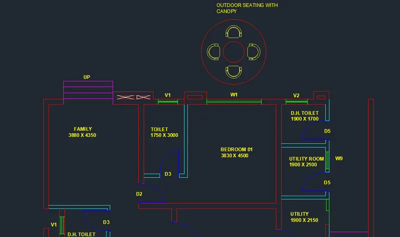
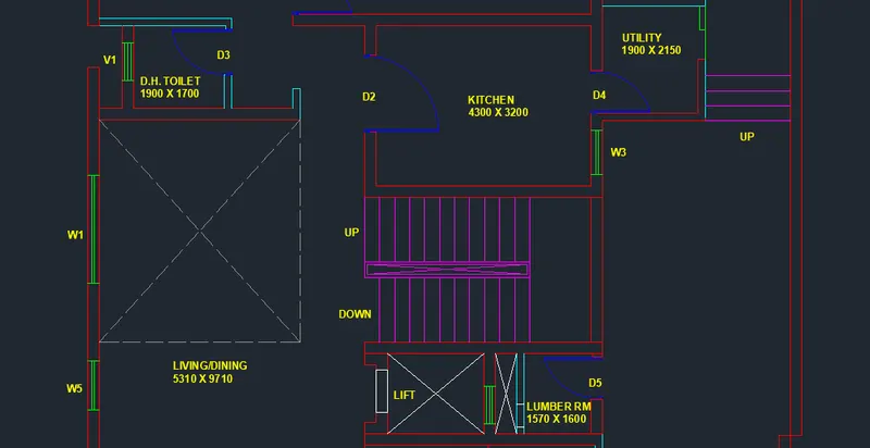
AIM : TO DRAW THE FLOOR PLAN.
- STEPS :
- Open Auto Cad and enter UN (units command) in command box and make the type as decimal.
- Select X line command and draw horizontal as well as in vertical direction.
- Trim the unwanted lines.
- Give the offset as follows for drawing the floor plan in horizontal direction- offset 230mm for external wall, offset 36880 mm for family room, offset for 230 mm wall, offset 1750mm for toilet, offset 150 mm for wall, offset 3830mm for guest room, offset 230mm for wall, offset 1900 for toilet, offset 150mm for wall.
- Give the offset as follows for drawing the floor plan in horizontal direction- offset 230mm for external wall, offset 4350 for family room, Offset 150mm for internal wall, offset 1650 for powder room, offset 9710 for living om, offset 230 for wall.
- Trim the unwanted edges and corners.
- Use offset command for drawing of staircase and steps.
- Use line command for drawing of windows doors\
- Use arc command for drawing swing of door.
- Use dotted lines o show the projections.
- Use the command multi line text to name the rooms.
- Use ellipse command to draw the outdoor seating canopy.
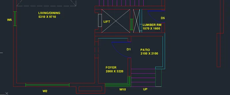
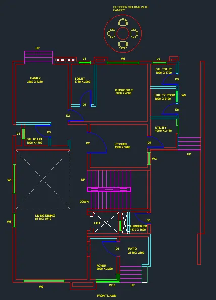
PROBLEM 3 :
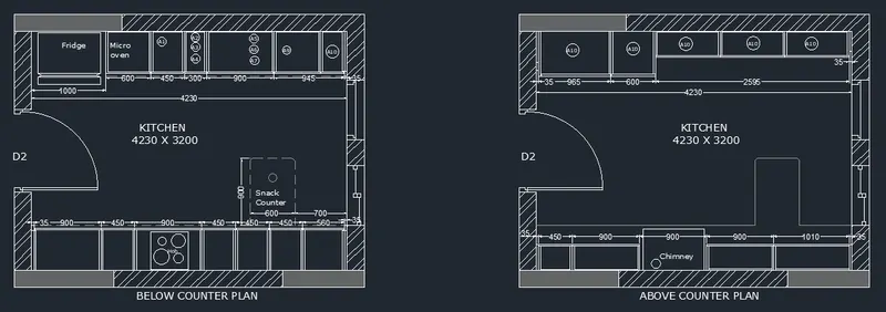
AIM : TO DRAW A KITCHEN PLAN.
- Steps for drawing Below Counter Plan-
- Open Auto Cad and enter UN (units command) in command box and make the type as decimal.
- Select line command and draw a line of 4300 in X direction and a line of 3200 in Y direction and complete the rectangle.
- Offset 230 towards all sides of the rectangle outside the figure.
- Fillet all the offset edges.
- Offset of 600 from top of the room to draw the kitchen platform ink and otta.
- Give the offset as follows from left side 90 as first offset- 90mm as first offset, 1000mm for fridge, 600 for micro-oven, 450 for A1 part, 300 for A2/A3/A4, 900 for A5/A6/A7, and 300, 945
- and 35 offsets.
- Offset 12 mm to both sides in each corner of the room.
- Offset 600mm from bottom in middle o kitchen to draw platform.
- Now enter offset as follows- 900, 450, 900, 450, 450, 450, 560, 35.
- Hatch the brick wall wit hatch type as ANS132 and hatch other part as solid and grey colour.
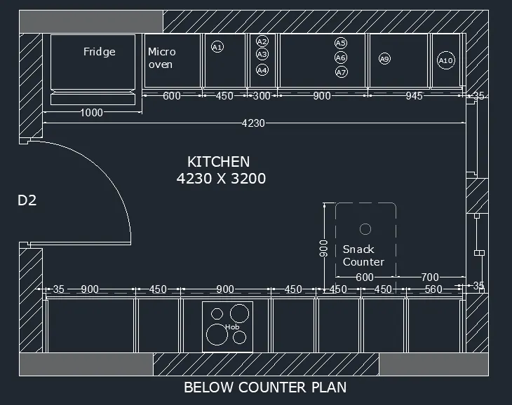
- Steps for drawing Above Counter Plan :
- Open Auto Cad and enter UN (units command) in command box and make the type as decimal.
- Select line command and draw a line of 4300 in X direction and a line of 3200 in Y direction and complete the rectangle.
- Offset 230 towards all sides of the rectangle outside the figure.
- Fillet all the offset edges.
- Offset of 600 from top of the room to draw the kitchen platform ink and otta.
- Give the offset as follows from left side 35 as first offset and again the offset as 965, 600, 2595.
- Offset 12 mm to both sides in each corner of the room.
- Offset 350 mm from bottom in middle of kitchen to draw platform.
- Now enter offset as follows- 35, 450, 900, 900, 900, 1010, 35.
- Hatch the brick wall with hatch type as ANS132 and hatch other part as solid and grey colour.
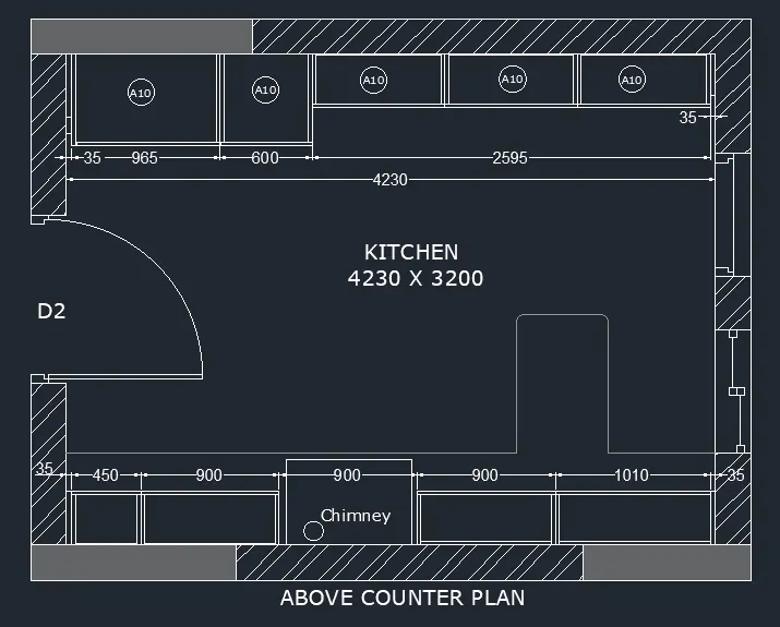
FINAL DRAWING :
PROBLEM 4 :
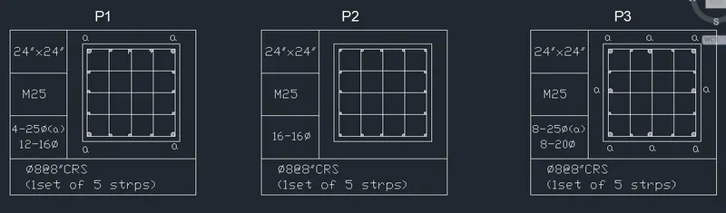
AIM : TO DRAW COLUMN DETAILS.
- Open Auto Cad and enter UN (units command) in command box and make the type as engineering and set precision as 0’-000’’
- Select line command and draw a line of 24’’ in X direction and line of 24’’ in Y direction.
- Select offset command and draw an offset of 1.2’’ in all four sides.
- Trim the unwanted corners.
- The two rectangles one inside other will be appearing.
- Divide the inside rectangle in 4 parts both in X as well as in Y directon.
- Select the circle command and draw the bars as follows.
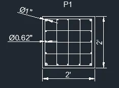
- IN P1-
- Four corner bars will be of 25mm that is 1’’ and rest of bars will be 16mm that is 0.62’’.
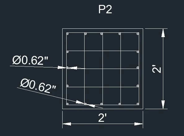
- IN P2-
- All bars will be of 16 mm that is 0.62’’
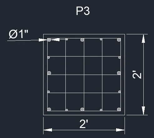
- IN P3-
- 8 bras will be of 25mm that is 1’’and 8 bars of 20 mm that is 0.8’’
- Create the table of suitable size and enter text by Dim linear command
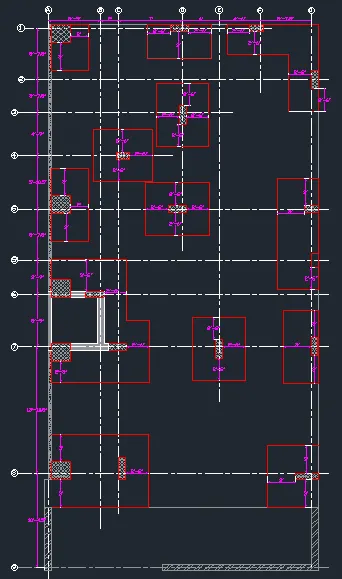
FINAL RESULT :
PROBLEM 5 :
AIM : TO DRAW A RAFT LAYOUT.
STEPS-
- Open Auto Cad and enter UN (units command) in command box and make the type as engineering and set precision as 0’-000
- Select the X line command draw line in X as well as in Y direction that is horizontal and vertical direction.
- Now enter the offset as follows in the X direction one after other offset as follows in following manner- offset 5’-7.5’’, 3’-7.5’’, 4’-9’’, 5’-10.5’’, 5’-7.5’’ ,3’-9’’, 5’-9’’ ,13’-10.5’’, 10’-4.5’’.
- Now enter the offset in Y direction as follows one after another offset 5’-9’’, 2’-0’’ , 7’-0’’ , 4’-0’’, 4’-6’’, 5’-7.5’’ , 9’’.
- Now we have to convert all the offset lines in construction lines.
- Select all the lines of offset drawn.
- Go to the layer option in ribbon- In ribbon- select other- the line type window will be opened- in that select load and select the Isolong-dash short dash and set scale as global scale factor as 12.
- Then draw the sizes of column with regular line as 24’’X 24’’, 9’’X 24’’, 9’’X 18’’, 9’’X24’’.
- Hatching all the lines-
- Hatch the lines of brick wall with the type as ANS132.
- Hatch concrete pat as AR-CONC.
- Hatch foundation to type as AN137.
- Extend the construction lines outside the box or figure and name each of the line in X manner as ABCD and Y manner as 1234.
- Draw circle with diameter 1’’ and insert the alphabets or numbers in it.
- Give the dimensions by DIMCONTINUE command.
- Give the text height as 8’’
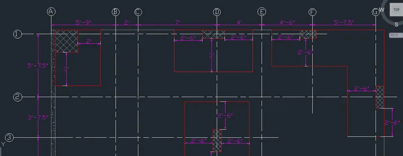
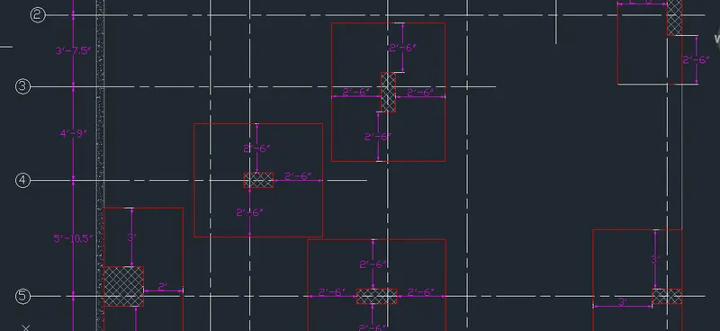
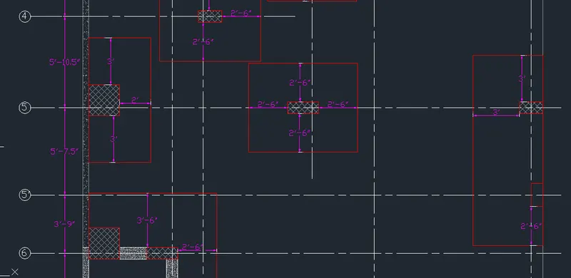
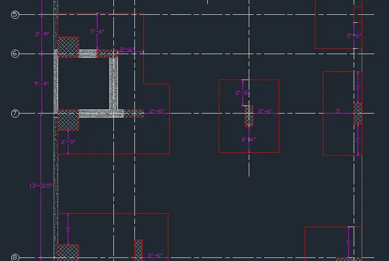
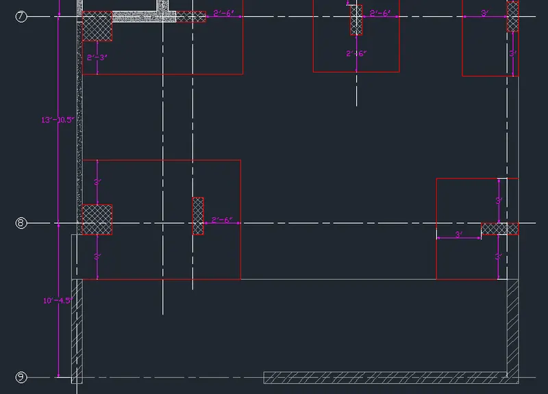
FINAL DRAWING :