Creating a Wardrobe detailed drawing, Floor Plan, Kitchen Layout and Column Detail using AutoCad
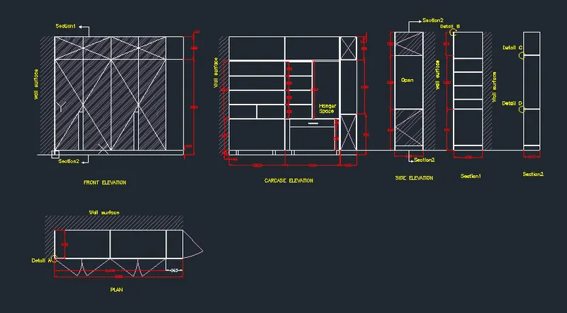
1.WARDROBE
Aim
To draw the elevation and details of a wardrobe given
Procedure
Firstly Units are set to mm that is decimel
In the command line type rec>2800, 2600 and type offset from the top of dimensions 12 and 488 mm.
In the command line type offset the offset from the side at the distance of 608.75 and 365 .
In the command line type L and by increasing the transparency to create wall surface by using hatch give the hatch and give scale 20.
In the command line type q leader to mention the annotations
The command prompt type rectangle > 630 x2800
The command prompt type rectangle 2800 X 2600 With the help of line command drawers and cabinets are created .
In the command prompt type rectangle and dimensions of 520 x 630, 1180 x 630 ,900x630 This is repeated 2 times.
using line commands, the next of the lines are drawn
Use layer option and choose different colors
Create new layer for TEXT,DIMENSIONS,HATCHING
Select these things and select its particular layer
Result
Thus the given elevation and details of wardrobe are drawn
2. FLOOR PLAN
Aim
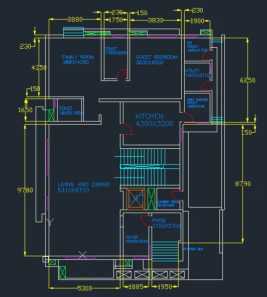
To draw the given floor plan of building
Procedure
Give an offset of 3880mm from the wall thickness and offset of 230mm for the other side.
Draw an offset of 300mm as wall thickness from the horizontal construction line.
Draw another offset of 4350mm from the 300mm wall thickness for drawing the
Give an offset of 1750mm from the right wall of family room ,also offset of 150mm to show wall thickness
Draw an offset of 250mm from the horizontal construction line for the wall thickness of toilet on outside side.
Draw an offset of 3000mm from the wall thickness ,so that the toilet is formed.
From the ofseted line ,draw 150mm for the wall thickness inside.
Draw an offset from the wall of toilet at a distance of 3830mm.
Also offset the wall thickness of 230mm.
Offset 4500mm from the horizontal wall and also offset 230mm from that line.
Take offset from the guest bed room wall of distance 1900mm towards the right side.
Also offset wall thickness of 150mm from that line.
Offset a distance of 1700mm from the horizontal line ,wall thickness of 230mm .
Also offset a wall thickness of 150mm .
Trim off the rest of line of horizontal construction line.
Take an offset of 2100mm downwards the wall of DH toilet
Also offset the wall thickness of 150mm.
From the utility wall take an offset of 2150mm downwards andl also wall thickness of 150mm.
From the left wall of dishawasher utility room ,take an ofset of 4300mm to the left and wall thickness of 230mm .
From the wall of guest bedrrom draw an offset of 3200mm downwards and also wall thickness of 230mm.
Extend the topwall of kitchenupto a distance of 1462mm excluding wall thickness.
Draw offset from the wall of living room 2000mm to the right and wall thickness of 230mm.
Draw the width of room 3220mm offseting from the line (wall)extended from the living room
Offset the wall thickness of 150mm.
Again offset 230mm for the lift wall and extend it to right end.
From the wall thickness of 230mm( extended lift wall) draw an offset of 2100mm downwards.
From the wall of foyer draw an offset of 2150mm and a wall thickness of 150mm on the right side.
From the wall of patio draw an offset of 1600mm towards backside.
Offset a wall thickness of 230mm .
To left side give an offset of 150mm as wall thickness
Draw an offset of 500mm from the 150mm wall of lumber room and wall thickness of 230mm.
Take an offset of 1620mm from the wall for lift .
Draw the side walls and front walls of 230mm.
Divide the stair room and offset 200mm to two sides by offset from the centre line.
Draw the first step ,then offset 300mm (tread) upto 11 divisions (12 steps in a flight),no of treads will be 11.
Rest of the portion forms landing ,draw 10 treads from the landing on other side of division.
Create ducts at the front and backside
Steps on back with tread 350mm and side 250mm.
Select the dimension tool from toolbar and select the lines which the dimesion to be displayed.
Dimension all the rooms and wall thickness.
Also dimension the total length of each side.
Text is written with multiline text .
Select multiline text- draw the text box- make text height as 300mm and style as romans.hsx. Command "ST" .
Give names and measurement of each room.
Give the designation of doors and windows.
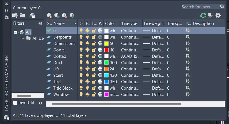
Click on layer properties in toolbar layer properties manager dialogue box appears - click on create new layer.
Layers are created for 230mm wall , 150mm wall, doors,windows,ducts,stairs,text .
Different colours are assigned to different layers for identification.
Each of the items are selected and are assigned respective layers.
Result
Thus the given floor plan is sketched with the help of layers
3. KITCHEN LAYOUT
Aim
To draw the give kitchen layout
Procedure
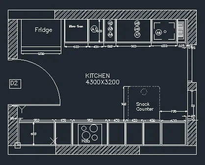
Draw a rectangle of 4300 and 3200mm
Draw offset 230mm as wall thickness towards outside.
Fridge is drawn on leftmost side by rectangle tool.
Take an offset of 1000mm and start drawing slab showing cabinet below
Offset 600mm for cabinet below for microwave oven ,give an offset of 20mm to show the partition of cabinet below.
For width of cabinet give 600mm offset , give 20mm inside offset and 10mm offset for thickness.
From 600mm offset of microwave cabinet ,give an offset of 450mm for A1.
From that give 300mm offset A2,A3 ,A4 .
From 300mm offset give another offset of 900mm for A5,A6,A7.
Draw 35mm offset from the right side for the hinge and give thickness of 20mm.
From the 35mm draw an offfset of 300mm towards left for the cabinet below sink drain and rest will be cabinet below sink. (assumed 300mm from right).
For all the divisions of cabinet ,take 20mm on both side to show the thickness.
To create doors, extend the line of all the divisions and give 10mm offset on both sides in the 10mm offset given for thickness.
Erase the extended line and trim the horizontal line for opening of doors.
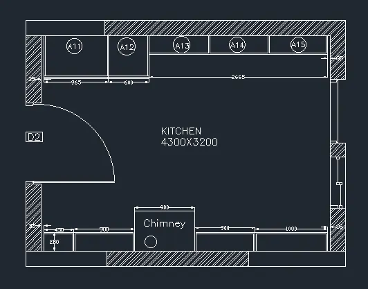
Create door on the left wall of the kitchen on both the plan.
Consider door of 900mm width. Trim 900mm from the wall thickness.
Draw a hinge of 20mm , and draw circle from centre of one hinge to another
Draw vertical line from one hinge to the circle to show the opening .
Trim off the rest of circle.
To draw the window,consider window of width 900mm .
From the 600mm width of cabinet ,take an offset of 900mm ( in line with the snack counter).
Draw the hinges and shutters of windows by using line tool.
To draw sliding doors take 200mm offset from the window.
Give an opening of 900mm take offset of 900mm from the 200mm offset.
Draw the shutters of the sliding door.
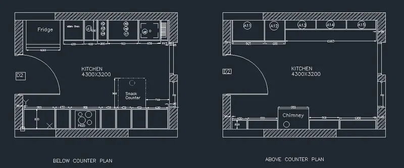
Copy it in the other plan also.
Dimension all the objects by dimension tool in the toolbar.
For text , select multiline text size -75mm style romans.shx .Command "ST".
Write all the text in respective places like fridge, hob, cabinet number etc
Result
Thus the given kitchen layout sketched with details
4. COLUMN DETAILS
Aim
To draw the column details with rebars sizes
Procedure
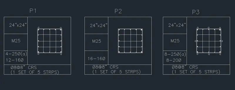
Open Auto Cad and set it to imperial ,as the drawing is in feet and inches.Set the limits -zoom all
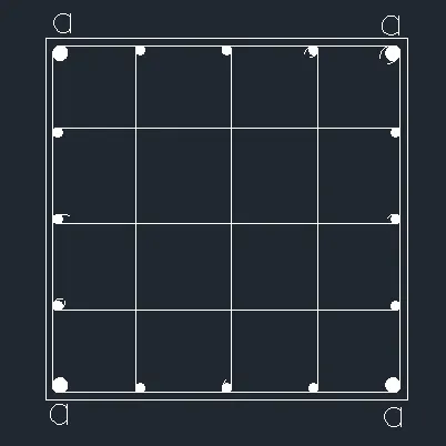
Drawing P1: Column of size 24" x24" having 4 bars of 25mm dia and 12 bars of 16mm diameter and connected by 8mm diameter stirrups.
Create rectangle by rectangle command with dimensions 24" x24" .
By offset command create an offset of 0.5" to show the column outline.
Explode the inner rectangle so that the lines can be selected seperately.
Drawing reinforcement for P1: Draw circle with tan -tan radius method with tangent as the two sides of column and 0.5" radius .
As the four corners are having 25mm dimaeter bars, mirror the circles by command "MI" and drawing horizontal and vertical planes.
Drawing 16mm dimaeter 12 bars
Using divide command divide the leftmost line of the column by command "DIV" - enter the no: of segments as 4
By Command "DDPTYPE" seelct the point so that it is visible
Now create a circle with centre radius method with radius as 0.31"(16mm dia bars) and place the side of circle with centre of point.
Copy the two circle and place it in the position of the points
Mirror the 16mm diameter bars by drawing vertical mirror plane. and delete the points created.
Again divide the horizontal lines into 4 segments and copy the circle and place the side of circle in the centre of the point.
Connect the bars by 8mm stirrups for that draw line with line command connecting the 16mm diameter bars.
Draw the rings by arc- 3 point method , and mirroring it.
Fillet the corners of the colum outline with filet radius as 0.5".
Use donout command to fillthe circle Command "DO" - specify the inner dimaeter as 0 and outer diameter as 0.1" for 4 corner reinforcement and 0.62" for inside reinforcement -specify centre of the donout , it gets filled.
Mark "a" for in between reinforcemnet to indicate it as 25mm diameter by singleline text with text height 2".
Similarly repeat with its respective dimensions for P2 and P3.
Result
Thus the given column details for P1,P2,P3 are drawn
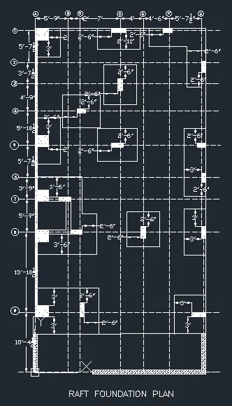
5. RAFT FOUNDATION
Aim
To draw the given raft foundation
Procedure
Open Auto Cad and set imperial units and change the units as architectural so that the dimensions are in fractions of feet and inches.
Drawing grid lines:
Draw an vertical line with construction line Command "XL-V ".
Offset the vertical line by offset command with offset distance 5'9" ,2'0" ,7'0", 4'0",4'6" , 5'-71/2".
Draw an horizontal line with constrcution line Command "XL-H".
Offset the horizontal lines by offset command with offset distance 5'-71/2" ,3'-71/2" ,4'9" ,5'-101/2",5'-71/2",3'9",5'9", 13'10-1/2",10'41/2".
Change the line type of these lines as ISO dash by clicking on line type and selecting load from the dialogue box and make ISo dash current linetype.
Mark the horizontal lines from 1 to 9
Mark the vertical lines from A to G.
Draw the bottom thickness of wall as 9" with the grid line at the centre.
A thickness of 41/2" is drawn from the grid line inside the left vertical grid line.
For Column: From the 41/2" thickness line draw a rectangle of 24" x24".by "REC" command giving the base point and giving dimensions as 24" and 24" and place the rectangle in the required position.
Explode the rectangle by commnad "EX" .
From the column offset 2' vertically and 3' horizontally
By fillet tool with fillet radius zero join the lines drawn to make the mat.
Hatch the column by command "H" and selecting "ANS 137" and giving scale of 20".
From the grid point D draw an offset of 9-1/2"
Create rectangle by selecting base point as 9-1/2" line and giving dimensions as 24" and 9" .
Delete the 9-1/2" line
Explode the rectangle and give offset with a distance of 2'6" vertical lines on both sides and 3' horizontal line.
Fillet both the corners with fillet radius as zero.
Hatch the columns by command "H" . "ANS137" scale 20
Similarly do this for each column with its respective dimensions
Then finally texts are written using command 'DT'
Then the dimensions are marked 'DIMLINEAR'
Result
Thus the given raft foundation is drawn in autocad