Creating a Wardrobe detailed drawing, Floor Plan, Kitchen Layout and Column Detail using AutoCad
Introduction: Autocad is a commercial Computer Aided Design(CAD), It is marked and developed as Autodesk. It was first released on december 1982. Autocad derived from a program, which was beganed in 1977 and then released in 1979 called as Interact CAD, and also called in early documents od autocad as microCAD, Auto desk cofounder was Michael Riddle.
The first version of cad was released in december 1982 and was supported on CP/M-80 computers, By march 1986 Aotocad has became most uniquitous cad program worldwide. The file format of autocad was .dwg, and its interchange file format to DXF, have become a standard. Autocad was included support for .dwf, a format developed and promoted by Autodesk, for publishing CAD date. In year 2022 the Autocad 36th major version was released and the 12th consecutive year of Autocad foe Mac.
CAD is a technology which replaces manual drawing with automated process, if you are a drafter, desingner, architect or engineer you have been used 2D or 3D CAD programs i.e., Autocad or Autocad LT software. Autocad helps you in draft construction documentation, explore ideas for design, viaualise concepts through photorealistic renderings and gives how a design performs in real world.
Autocad mailnly used by industries, architects, engineers, city planners, project managers, graphic designers and other professionals.
1.
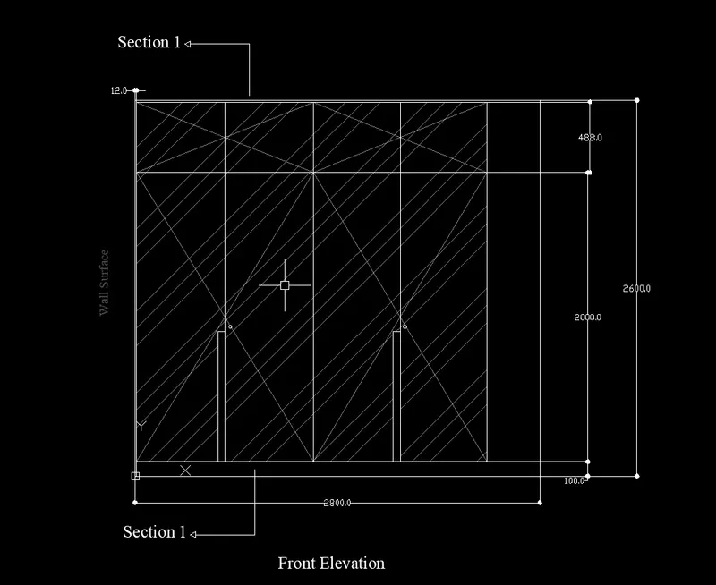
Aim: To draw the elevation and details of a wardrobe as given in the Figure, and to provide Dimensions and text using layers
Front Elevation:
Steps:
1. Open new file in Autocad 2023, Type UNITS, use decimal and take millimeters
2. Then LIMITS, Limits of lower left corner give (0,0) and limits of upper right corner (420,297)
3. Type DS (drafting settings) and go to snap and grid ON snap and grid, give snap X and Y spacing as 10, and Grid X and Y spacing as 10 and major lines are taken at every 5 minor lines.
4. Take Line command and first point is (0,0) and next points are (@2800,0) (@0,2600) (@-2800,0) (@0.-2600)
5. And using Offset, offset the left vertical line at a distances of 12, 611.5, 611.5, 600 and 600 in right direction, Then Offset the top horizontal line at a distances of 12, 488 and 2000 towards inward direction. And Trim the extra lines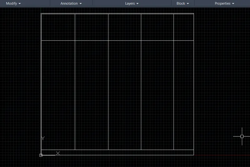
6. And using Line command provide the rectangle and also circle as given above the bottom horizontal line, And using Hatch Provide the hatch inside and provide Transparency of the hatch is 50
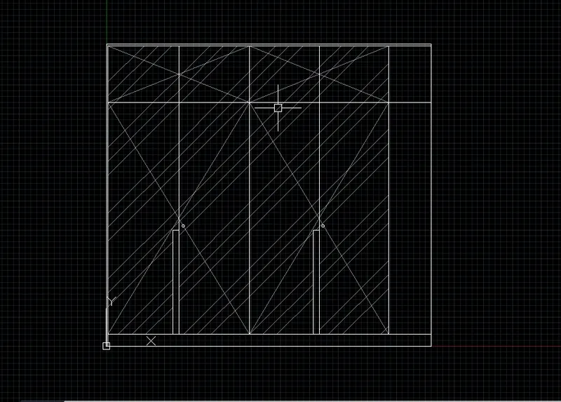
7. Now create two layers by clicking on Layer Properties from the Layers panel and name them as Dimensions and Text, First Set current layer as Dimension and using Dimlinear command provide the dimensions, then make Text layer as Set current and write the required text using Times New Roman Greek font and provided font height is 60
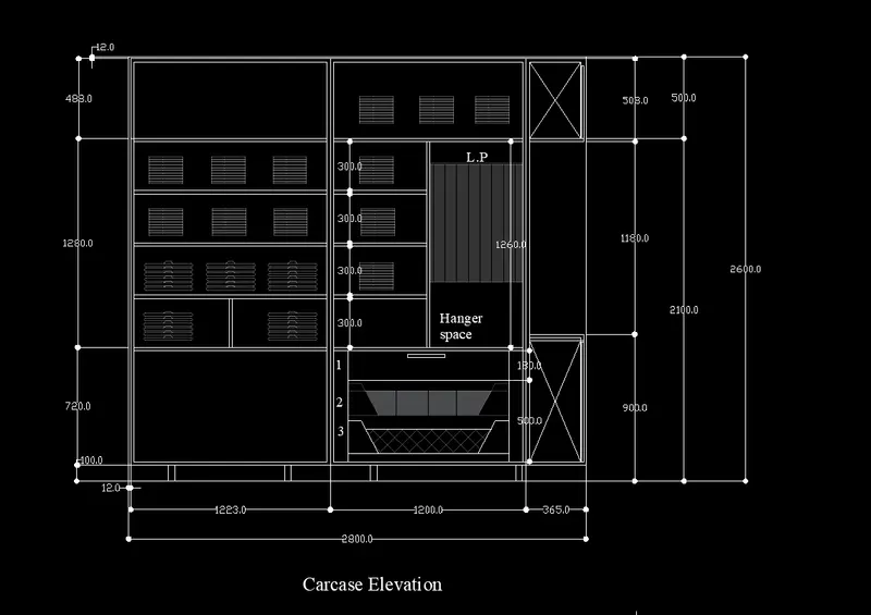
Carcase Elevation:
1.Take Line command and first point is (0,0) and next points are (@2800,0) (@0,2600) (@-2800,0) (@0.-2600)
2. And using Offset, offset the left vertical line at a distances of 12, 611.5, 611.5, 600 and 600 in right direction, Then Offset the top horizontal line at a distances of 12, 488 and 2000 towards inward direction. And Trim the extra lines
3. Now Offset the Inner walls to a distance of 20, towards inward direction and Using Trim remove the extra lines at the corners
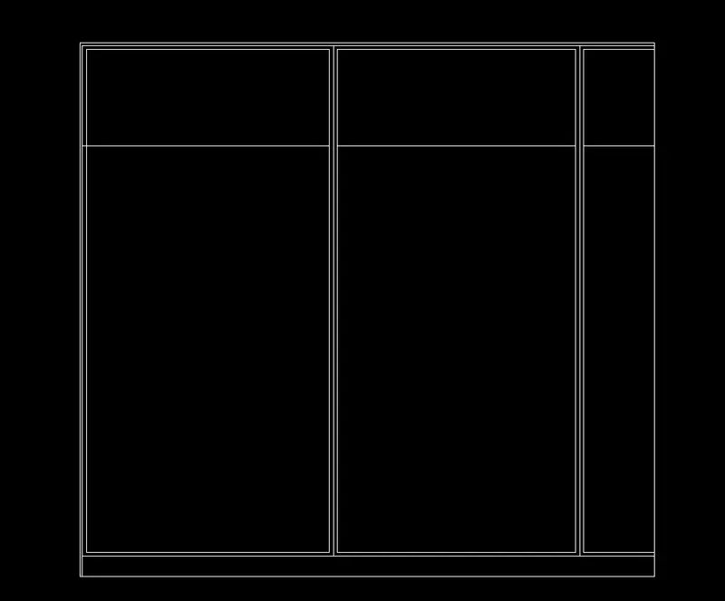
4. And in left side inner rectangle off set the bottom horizontal line at a distance of 680, 20, 300, 20, 300, 20, 300, 20, 300 and in the right side inner rectangle offset the bottom horizontal line at a distance of 680 and 20.
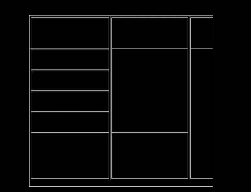
5. And in the right side inner rectangle the left vertical line is offsetted at a distance of 570 and 20, and the horizontal line offsetted to 300, 20, 300, 20, 300, 20, 300 and using Trim, trim the unnecessary lines.
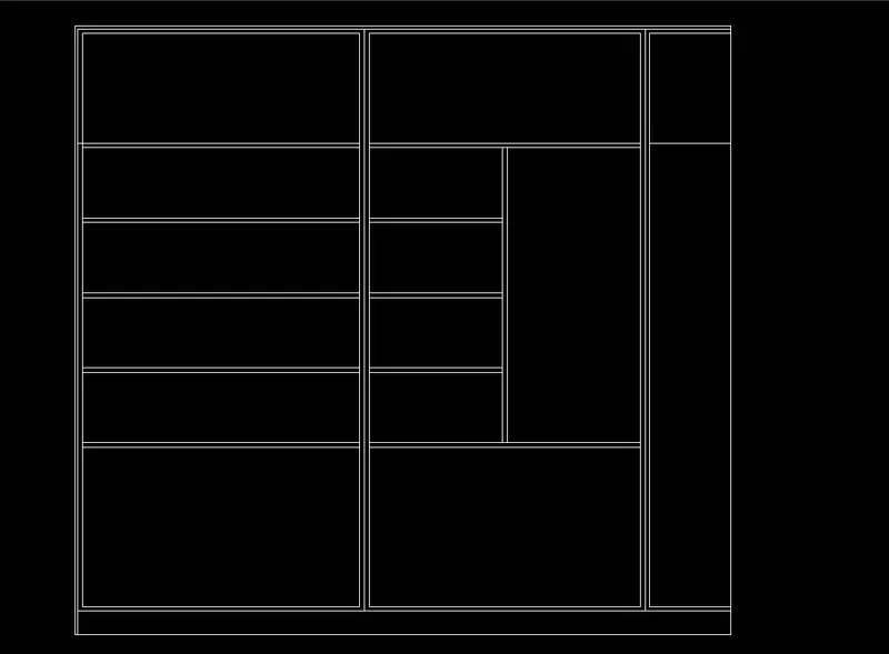
6. And in right most rectangle offset the bottom most horizontal line to 900 and provide the required inner lines by using Line command, ND use Trim to remove extra lines.
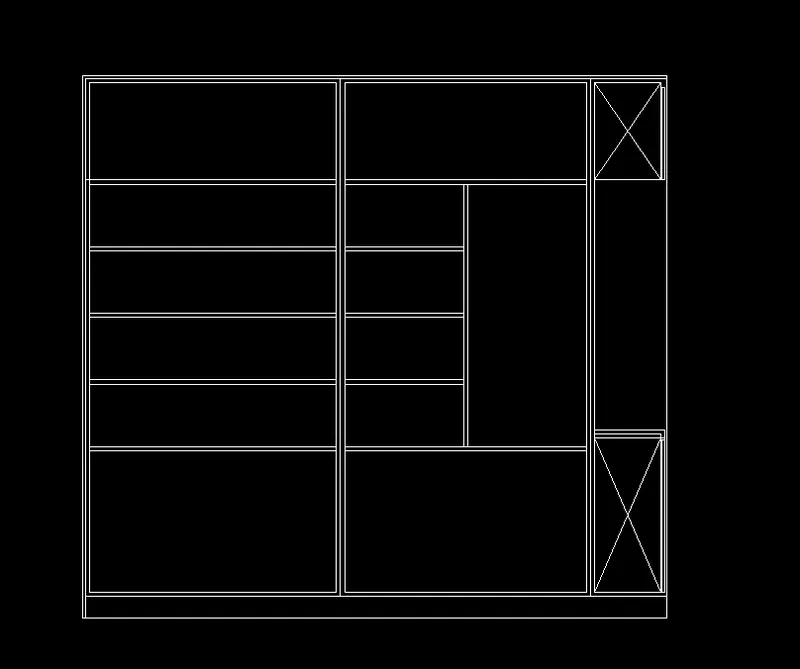
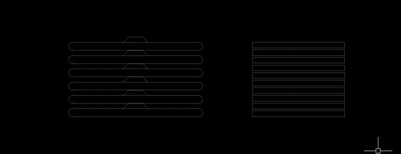
7. Then for hatching, using line command draw required shapes and provide the transparency 70, and copy it to required places in our drawing
And use Hatch command to provide hatching at required places
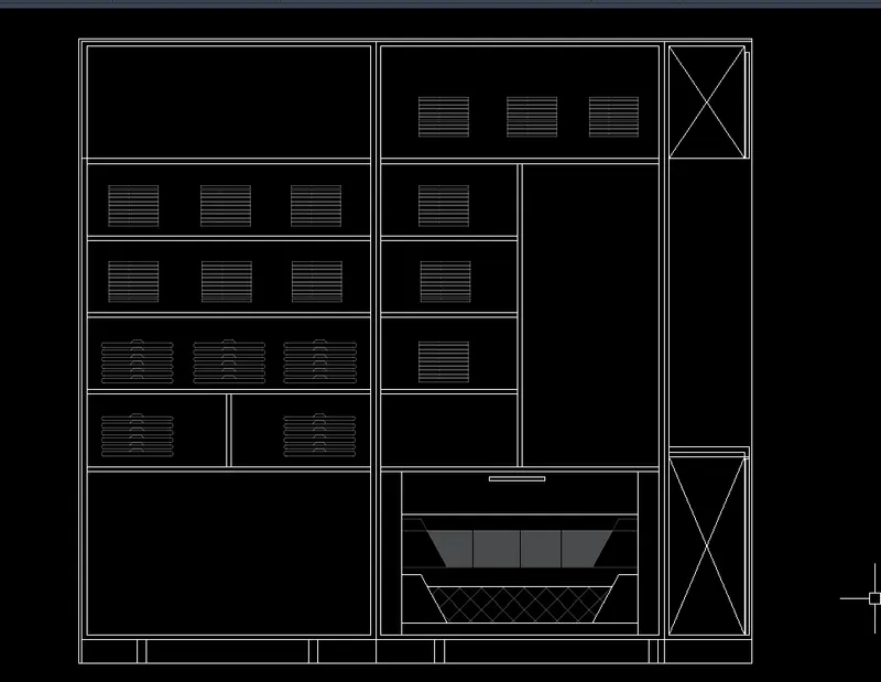
8. Now First Set current layer as Dimension and using Dimlinear command provide the dimensions, then make Text layer as Set current and write the required text using Times New Roman Greek font and provided font height is 60
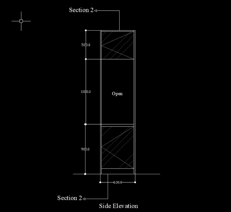
Side Elevation:
1. Use Line command and by direct distace method draw 630 in X direction then 2600 in +Y direction and 630 in -X direction and 2600 in -Y direction.
2. Now use Offset and offset the 2 vertical lines and top horizontal line 20 in inward direction
3. Then Offset the bottom horizontal line 100 and again from bottom to 900, 1180, Then offset the 900 distance line to 40 in -Y direction
4. Use Trim to remove the extra lines
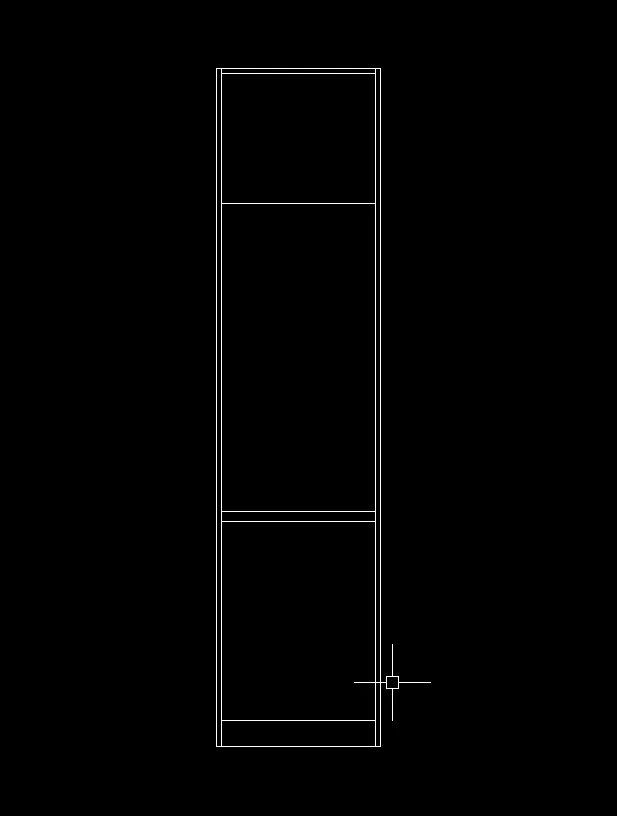
5.Now Set current layer as Dimension and using Dimlinear command provide the dimensions, then make Text layer as Set current and write the required text using Times New Roman Greek font and provided font height is 60
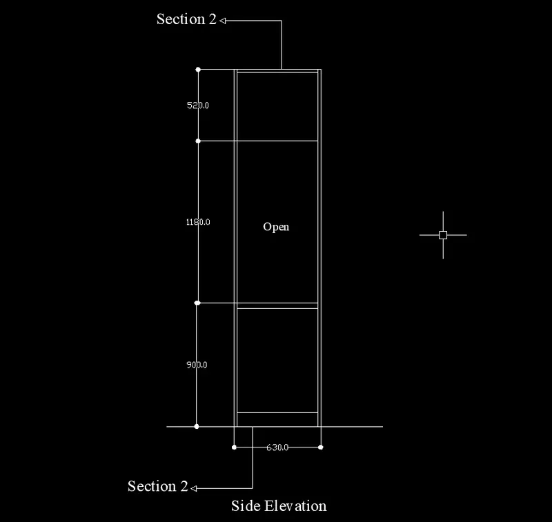
6. And using Hatch Provide the hatch inside and provide Transparency of the hatch is 50
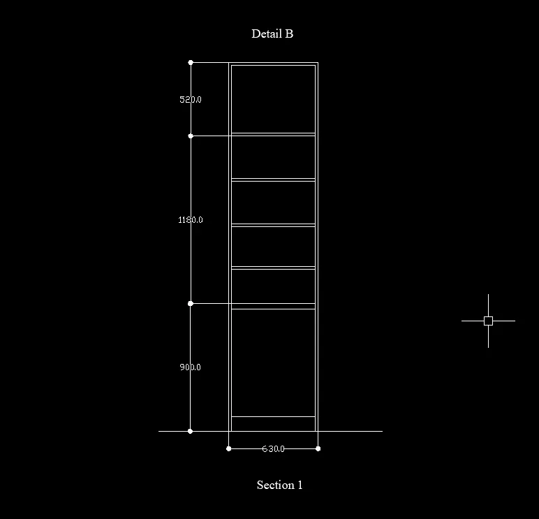
Section 1:
1.Use Line command and by direct distace method draw 630 in X direction then 2600 in +Y direction and 630 in -X direction and 2600 in -Y direction.
2. Now use Offset and offset the 2 vertical lines and top horizontal line 20 in inward direction
3. Then Offset the bottom horizontal line 100 and again from bottom to 900, 1180, Then offset the 900 distance line to 40 in -Y direction
4. Use Trim to remove the extra lines
5. And offset the Line that offsetted to 1180 to a distances of 300, 20, 300, 20, 300, 20 in downward direction and offset the same line by 20 in upward directon.
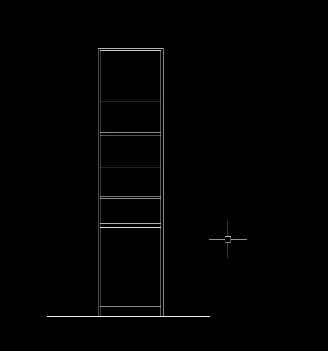
6. Now Set current layer as Dimension and using Dimlinear command provide the dimensions, then make Text layer as Set current and write the required text using Times New Roman Greek font and provided font height is 60
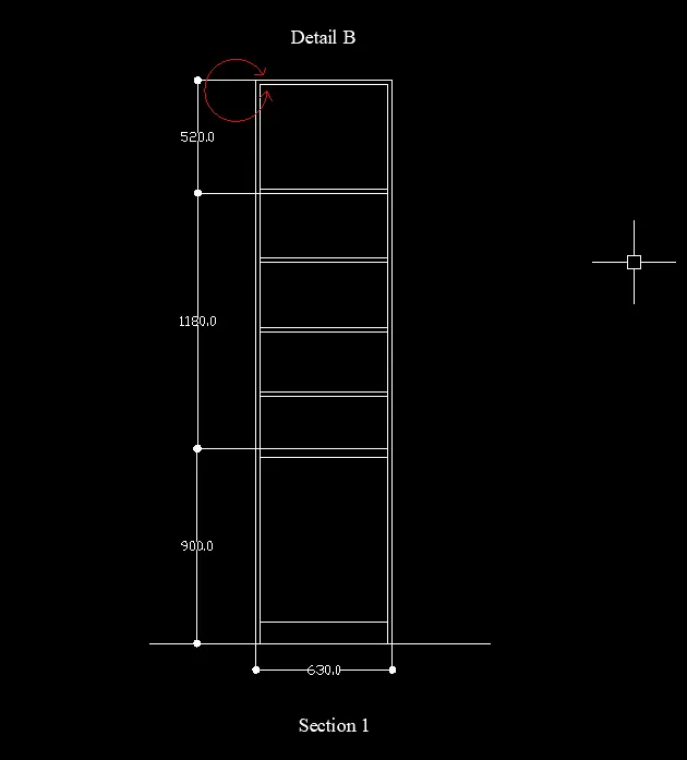
7. Using ARC - start center end create the provided moment with red colour.
Section 2:
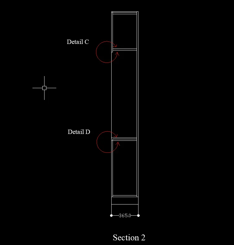
1.Use Line command and by direct distace method draw 365 in X direction then 2600 in +Y direction and 365 in -X direction and 2600 in -Y direction.
2. Now use Offset and offset the 2 vertical lines to 20 and top horizontal line to 12, 20 in inward direction
3. Then Offset the bottom horizontal line 100 and again from bottom to 900, 1180, Then offset the 900 distance line to 40 and 20 in -Y direction
4. Use Trim to remove the extra lines
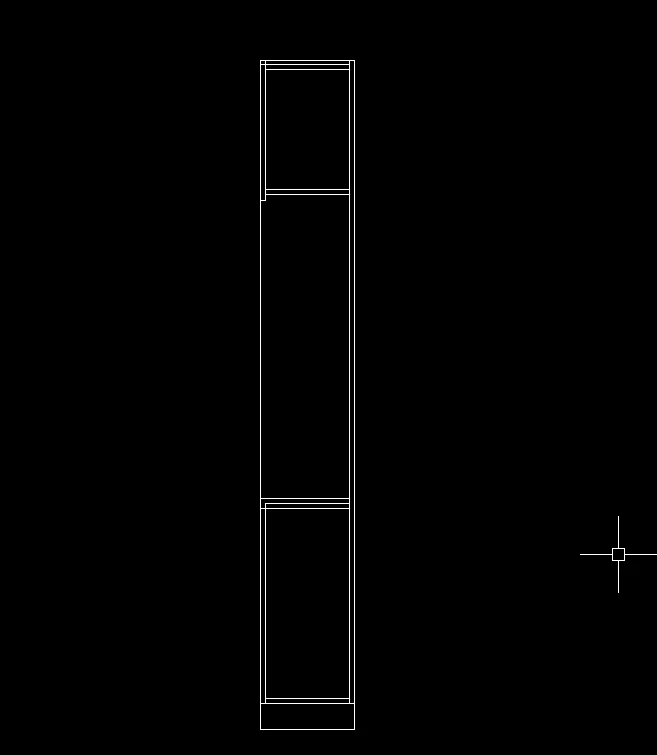
5.Now Set current layer as Dimension and using Dimlinear command provide the dimensions, then make Text layer as Set current and write the required text using Times New Roman Greek font and provided font height is 60 and using ARC - start center end create the provided moment with red colour.
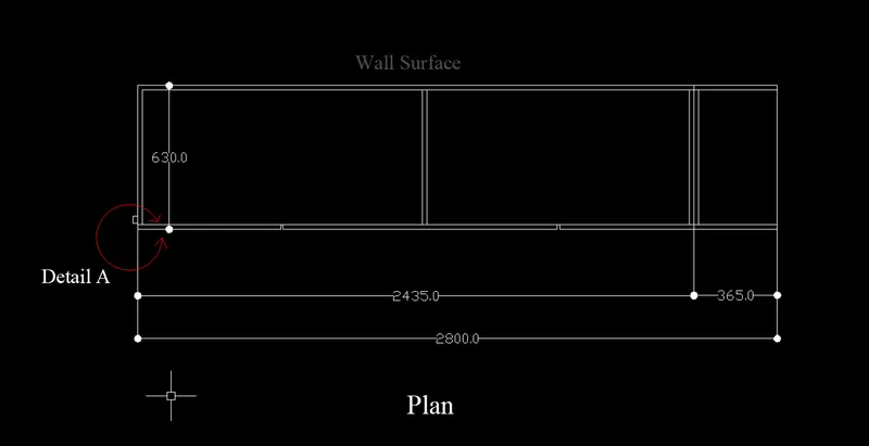
Plan:
1.Use Line command and by direct distace method draw 2800 in X direction then 630 in +Y direction and 2800 in -X direction and 630 in -Y direction.
2. Now use Offset and offset the 2 vertical lines to 20 and top horizontal line to 20 in inward direction and offset the left inner vertical line by 1235 and 1200 distance
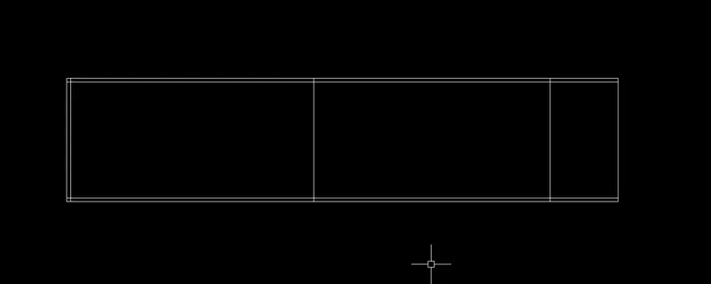
3. And offset the vertical line which is at 1235 from left inner vertical line by 10 on both sides, and offset the vertical line which is 365 from right vertical line by 20 on both sides
4. And using Trim, remove the extra lines.
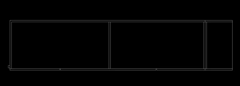
5.Now Set current layer as Dimension and using Dimlinear command provide the dimensions, then make Text layer as Set current and write the required text using Times New Roman Greek font and provided font height is 60 and using ARC - start center end create the provided moment with red colour.
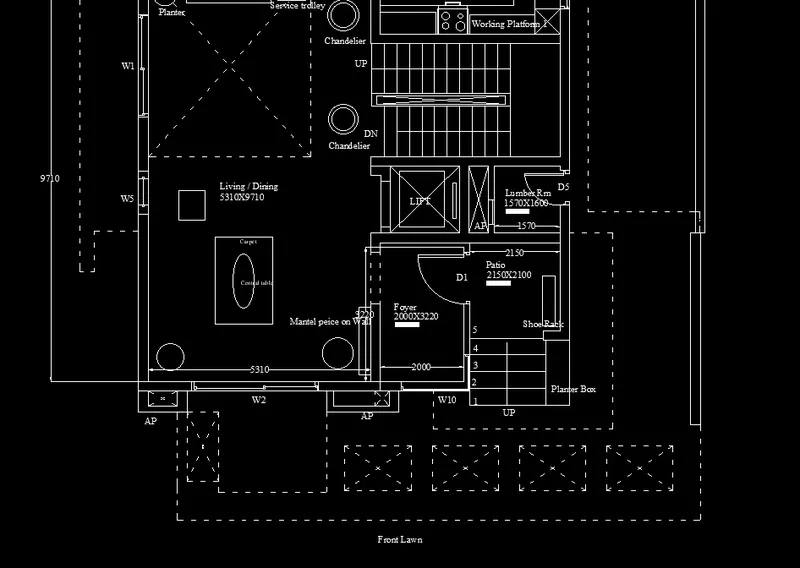
2. Aim: To draw given Floor plan using Auto cad
Steps:
1.Open new file in Autocad 2023, Type UNITS, use decimal and take millimeters
2. Then LIMITS, Limits of lower left corner give (0,0) and limits of upper right corner (1000,1000)
3. Type DS (drafting settings) and go to snap and grid ON snap and grid, give snap X and Y spacing as 10, and Grid X and Y spacing as 10 and major lines are taken at every 5 minor lines.
Import the given pdf to Autocad and use Scale command to adjust to our drawing page, The living room 5310 dimension measured in our drawing sheet as 70.61, so in order to scale to original length(5310) give scale factor of 75.2 (5310 divided by 70.61 is equal to 75.2)
4. Take Line command and first point is (0,0) and next points are (@12350,0) (@0,16700) (@-12350,0) (@0,-16700), a rectangle is formed 12350 X 16700
5.Now using Offset, Offset the horizontal lines and left vertical line by 230mm and right vertical by 150
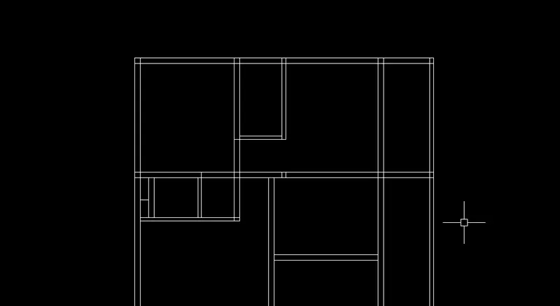
6. And again Offset the vertical wall at a distances of 3880, 230, 1750, 150, 3830,230, 1900 in right direction and the top horizontal wall offsetted by 4500 and 230 in inward direction.
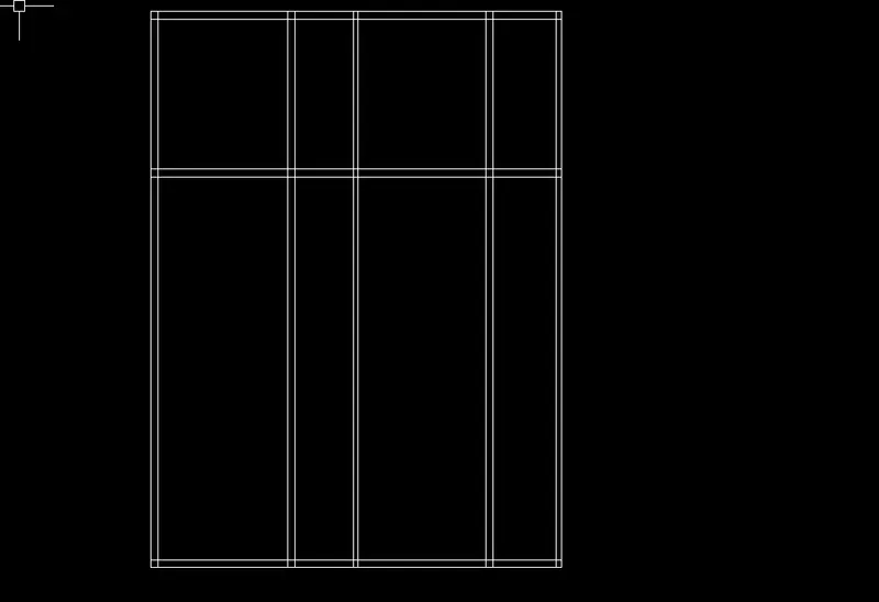
7. Now using Breakatpoint Command to do drafting easily Break the corner after the Family room to create Powder room, and offset that line downward by 1650 and 150
Then using Breakatpoint break the inner corner second vertical wall from right,and Offset that line by 4300 and 230 in left direction, trim the unnecessary lines.
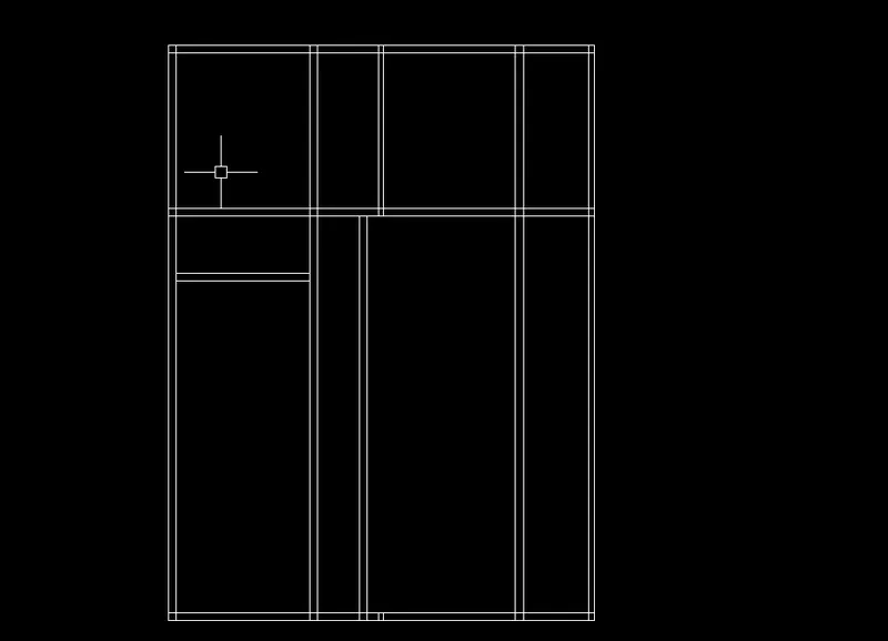
8.Now to create kitchen use Breakatpoint at the top corners of kitchen and offset it to a distance of 3200 and 230 in downward direction
Now in the same kitchen row using Breakatpoint and break the inner corners of the bottom horizontal line and Offset that line to a distacnces of 3300, 230, 1600 and 230 in upward direction
Next at the Foyer left corners are breaked using breakatpoint and that vertical line is offseted to 2000 and 150
And for Patio the top horizontal line is offsetted to 2100 and 230
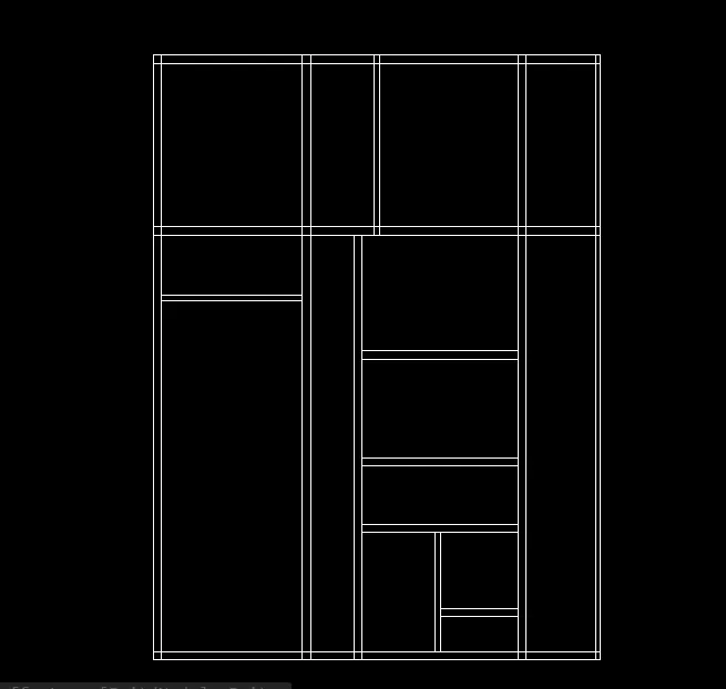
9. Now to create Powder room and Toilet 1, Break the inner horizontal wall of toilet 1 and offset it in downward by 3000 and 150
and Offset the inner vertical wall of powder room in right direction by 350, 230, 1800, 150
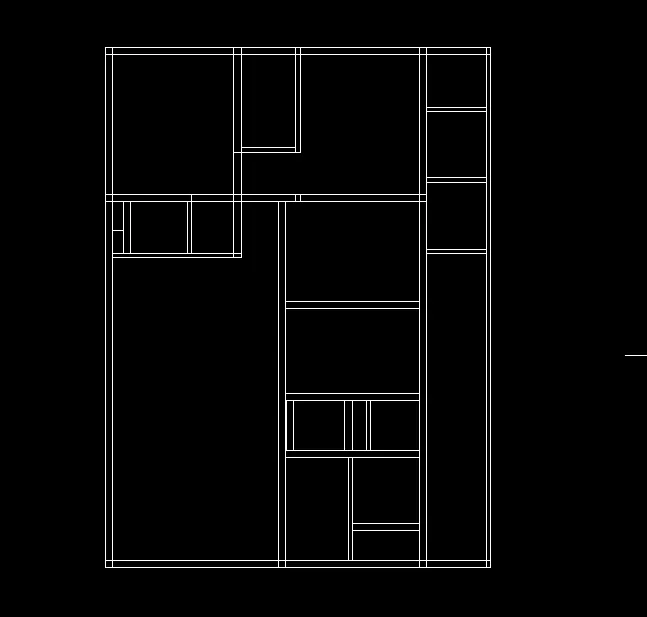
10.To create Lumber room and Lift, now from right vertical of lumber Offset in left direction by a distances of 1570, 150, 450, 230, 1650, 230
And to create D.H Toilet, Utility room and Utility the inner top horizontal wall is offsetted by 1700, 150, 2100, 150, 2150, 150 and trim to remove unnecesasary lines.
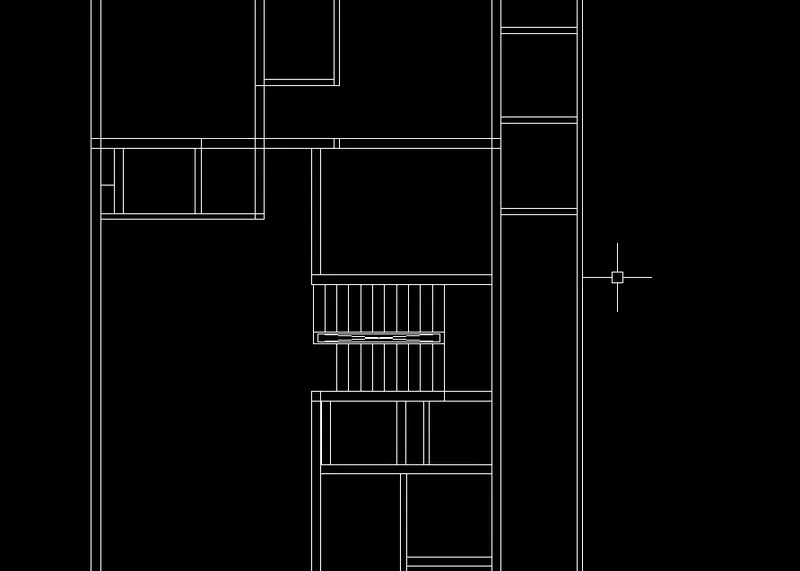
11. To create steps, Offset the right vertical wall to a distance of 1200 and then offset the top horizontal line by 1200, 300, 1200 and then the vertical line is offsetted at 300 for 12 times in the left direction to create steps and using Trim, remove the extra lines.
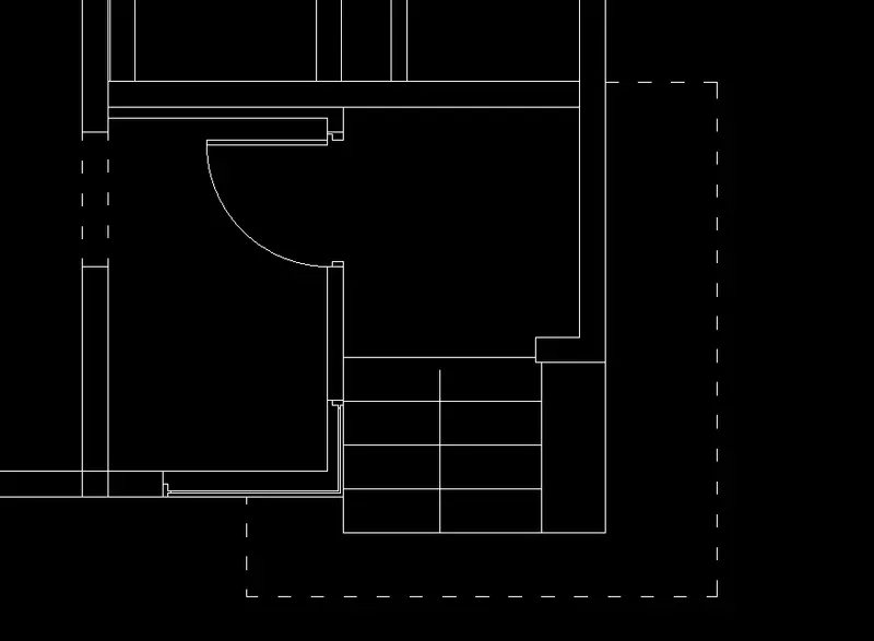
12. Now to create Foyer and Patio, The Door D1 width is 1230 and created by taking top horizontal line of Foyer by 225 and 1230 offset, and using trim the extra lines , the door Arc create by taking Arc - start end angle( give angle 90) then extend the door lines to opposite wall and make the vertical lines dotted lines
The window of foyer room dimensions are 1100 horizontal and 650 vertical , take offset and draw lines at 1100 horizontal and 650 vertical
The steps are created by taking offset of 400 from the left verical wall thickness and the step length is 1800 and width is 400, then take offset and the step horizontal line is offsetted 400 downward for 4 times
Using Line command draw required lines and make them to dotted
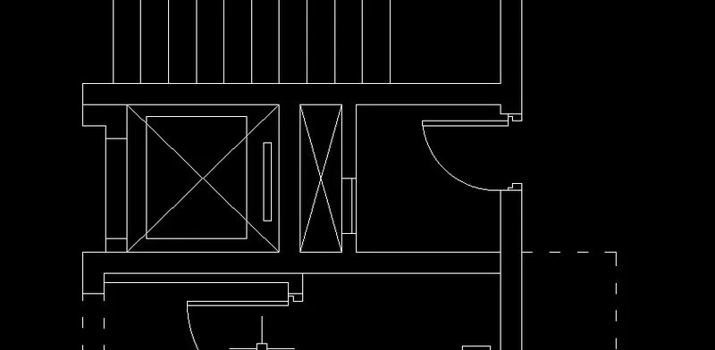
13. To create the Lumber room and Lift, The Door D5 of lumber room width is taken as 830 an offset from top horizontal thickness line is taken at 100, 830 and using line command and arc door is drawn
And the opening for AP unit is 600 width taken by a distance of 200 from bottom inner horizontal line, And the lift opening is taken as 1080 width at a distance 370 from top horizontal line
Using Line command draw the required lines and use Trim to remove extra lines
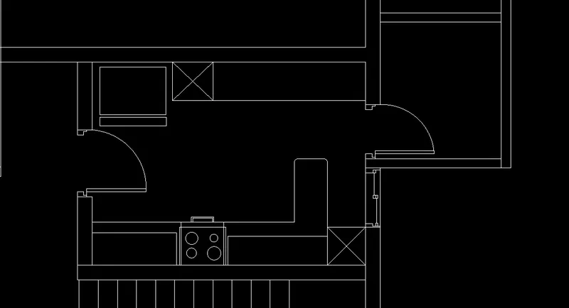
14. To create Kitchen, The Door D2 width is 1050 and at a distance of 1070 from top inner horizontal line and draw using Offset, The door D4 width is 850 which is at a distance of 670 top inner horizontal line and draw using Offset and using line command and arc door is drawn, And width of window is 930
And by Using Line command inner lines are drawn, use Trim to remove extra lines.
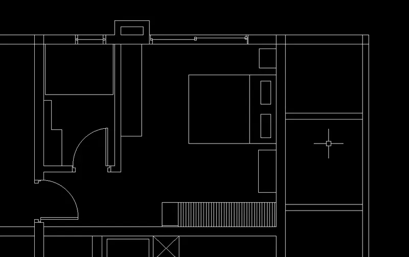
15. To draw Bedroom 1 and Toilet 1, The Door D2 width is 1050 and is at 100mm from bottom inner horizontal wall and Door D3 width is 950 which is at 100mm from right vertical wall of toilet
V1 of toilet has width of 750mm which is at a distance of 220 from right vertical wall
W1 of beadroom has width of 2440 which is at a distance of 700 from left vertical wall
And by Using Line command inner lines are drawn, use Trim to remove extra lines.
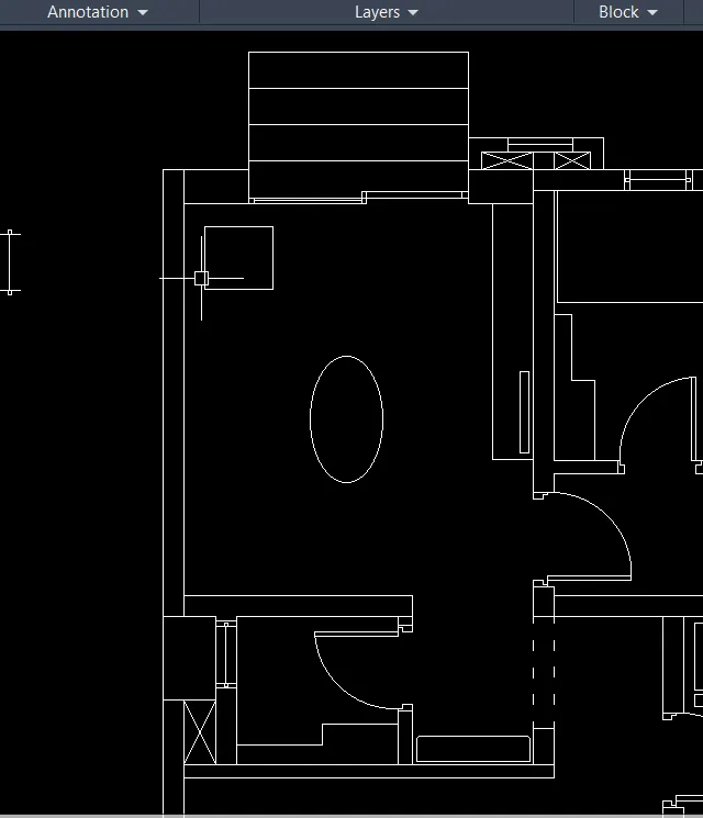
16.To draw Family room and Powder room, Firat the top horizontal wall thickness increased to 380, so outer wall is offsetted to 380 towards inward and the steps are at a distance of 720 from left inner vertical wall and the length of steps are 2430 and the width is 400 offseted for 3 times
The AP unit is at 350 from outer wall and about 1510 length
V1 for powder room width is 750 which is at 100 from top horizontal wall of powder room
D3 door for powder room width is 950 which is at 100 from top horizontal wall of powder room
And draw the lines and change to dotted at required
And by Using Line command inner lines are drawn and ellipse also used, use Trim to remove extra lines.
17. To draw D.H Toilet, Utility room and Utility, The D.H Toilet room door D5 width is 830 which is at 100 from bottom horizontal wall of D.H Toilet room
V2 for D.H Toilet room width is 630 which is at 100 from left vertical wall of D.H Toilet room
The door D5 of Utility room width is 830 which is at 100 from bottom horizontal wall of Utility room
The window W9 width is 730 and at 150 from top horizontal wall of utility room
The window for utility is 1000 width which is at distance of 900 from left vertical inner wall
The 3 steps are drawn after the utility room whose length is 950 and width is 300, Beside the D,H Toillet room another 2 steps are drawn
After the steps the Outer wall this drawn with thickness 230mm
And by Using Line command inner lines are drawn, use Trim to remove extra lines.
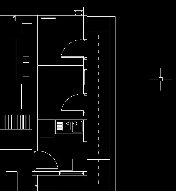
18. To draw Living and Dining room, The of W1 of dining room is 2430 and W5 width is 1030 are drawn from top horizontal wall and using offset at distances 950, 2430, 1300, 1030
The dining area lines are drawn using line with horizontal line is 3880 and vertical is 4330 and make them as dotted lines
The AP unit at bottom horizontal wall is drawn with vertical wall is 500 and horizontal length is 1160, and offset the vertical lines by 230 inwards and horizontal line by 150
From AP unit the W2 window is at 110 distance and the width of W2 is 3035
Another AP unit from W2 is at 200 distance with vertical wall is 500 and horizontal length is 1710, and offset the vertical lines by 150 and 230 inwards and horizontal line by 150
And by Using Line command inner lines are drawn also circle and ellipse are used, use Trim to remove extra lines.
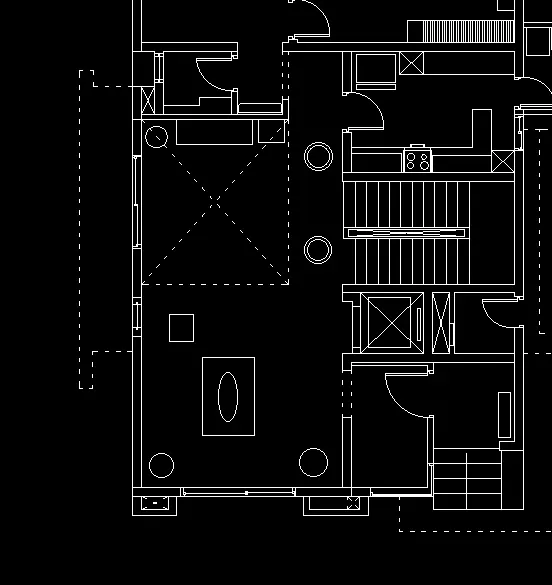
19. Now draw the required dotted lines using Line command by changing line type to dotted and final plan looks like.
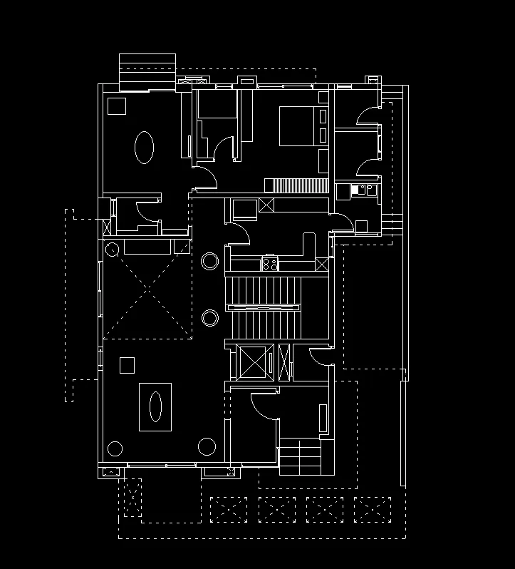
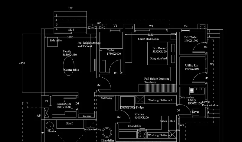
20. Mark the dimensions using Dimlinear and write the text at required place the used font style is Times New Roman Greek and font size is 150
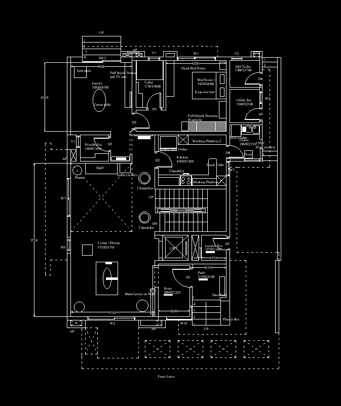
3.
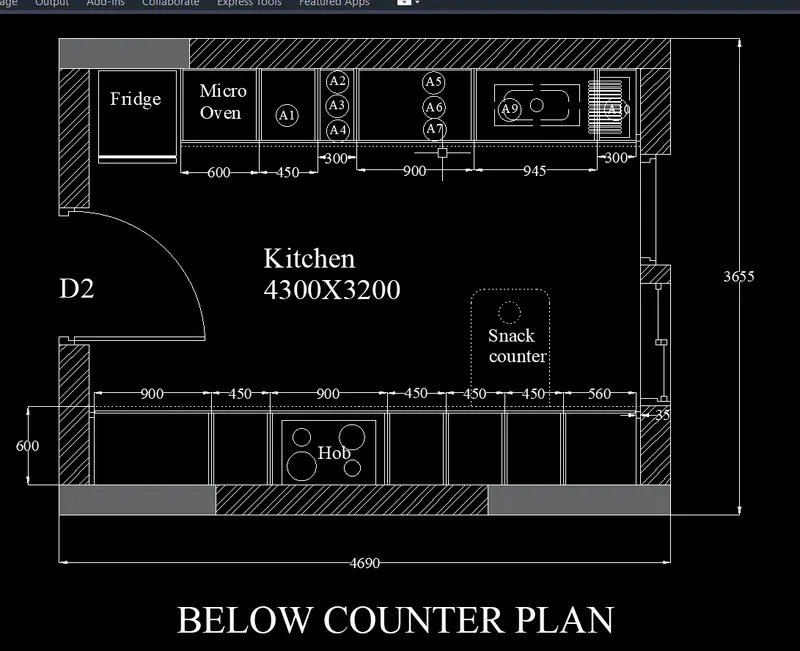
Aim: To create the kitchen plan as given in the figure using Autocad
Below Counter Plan:
Steps:
1.Open new file in Autocad 2023, Type UNITS, use decimal and take millimeters
2. Then LIMITS, Limits of lower left corner give (0,0) and limits of upper right corner (1000,1000)
3. Type DS (drafting settings) and go to snap and grid ON snap and grid, give snap X and Y spacing as 10, and Grid X and Y spacing as 10 and major lines are taken at every 5 minor lines.
Import the given pdf to Autocad and use Scale command to adjust to our drawing page
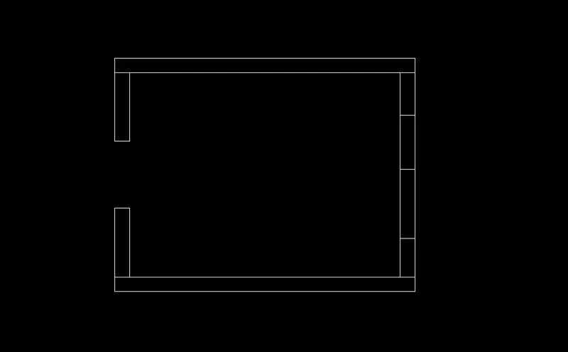
4.Using Line command a rectangle of size 4690X3655 and using Offset command, offset the all lines by 230mm in inward direction
Now the inner horizontal thickness line on left vertical wall top line is Offsetted in downward direction to a distances of 1070, 1050, 1075 and Using Trim remove the extra lines, so door D2 is created
Now the inner horizonta thickness line on right vertical wall top line is Offsetted in downward direction to a distances of 660, 850, 1080, 605
Using Trim remove the extra lines
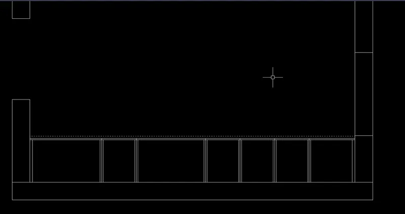
5. Now take line command and draw a reference horizontal line from right wall at a height of 835 to opposite end, Now offset that horizontal line 5 in downward direction and remove the reference line and make the offsetted line as Dotted line
The dotted line is offsetted by 30 in downward direction and that line is normal line again that line offsetted by 20 in downward direction
Using Breakatpoint, break the right inner vertical wall at joining of offsetted horizontal line, and now the vertical line in Offsetted in left direction to distances of 35, 560, 450, 450, 450, 900, 450, 900
Again the inner vertical lines, using Offset they are offsetted by 20 on both sides of that line
And using Trim, remove the extra lines
6. Draw a dotted vertical line which is at 700 from the right vertical wall, the lines drawn by direct distance method i.e., in Y direction 900 then in -X direction 600 and in -Y direction 900
The door D2 is created with width 1050 and the required lines in right wall is drawn using Line command.
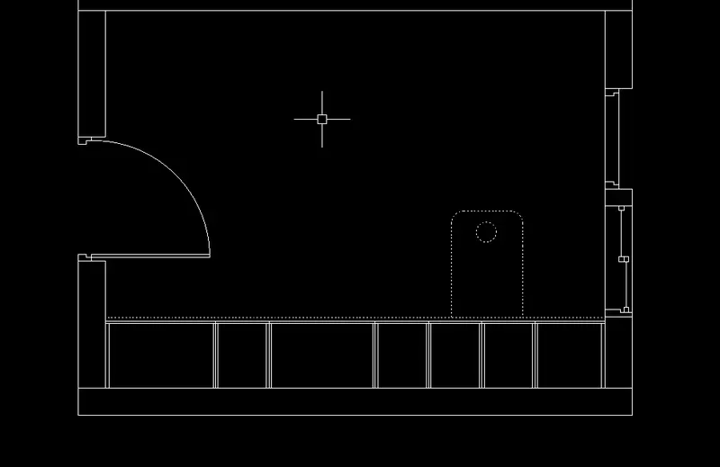
7. The inner top horizontal line is offsetted to 600 in downward direction ( that line is dotted line, later changed to dotted line) and that line is offsetted in upward direction by distances of 30 and 20
The right vertical inner wall is breaked at 600 and offsetted in left direction to a distances of 35, 300, 945, 900, 300, 450, 600
And the inner vertical lines are offsetted by 20 on both sides, the last vertical wall is offsetted by 20 only in inward direction. and offset the inner top horizontal line is offsetted to 5 in downward direction
And using line command fridge is drawn
And using Trim, remove the unnecessary lines carefully.
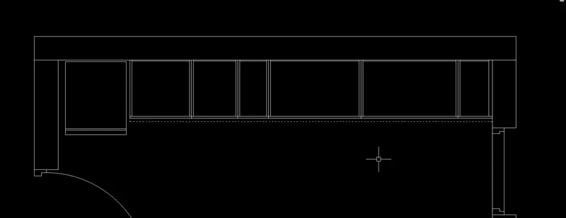
8. By using Line and circle all the inner lines are provided
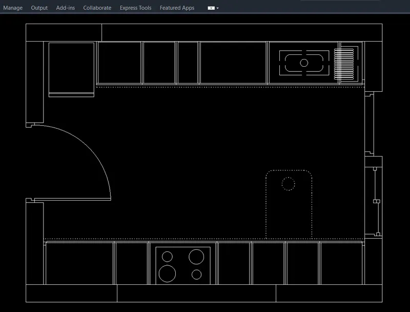
9. Mark the dimensions using Dimlinear and write the text at required place the used font style is Times New Roman Greek and font size is 150 and 100
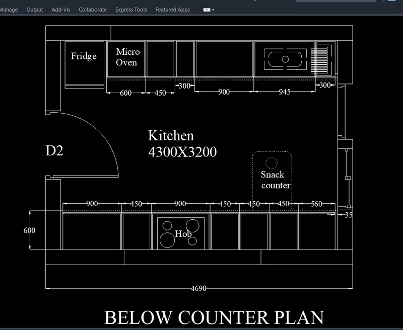
10.Using Hatch command, hatch the thickness of walls
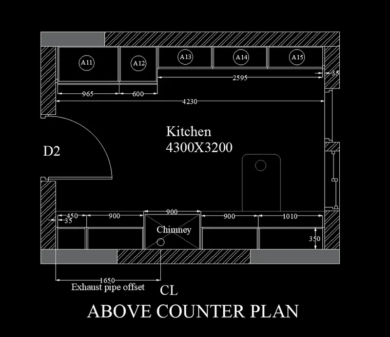
Above counter plan:
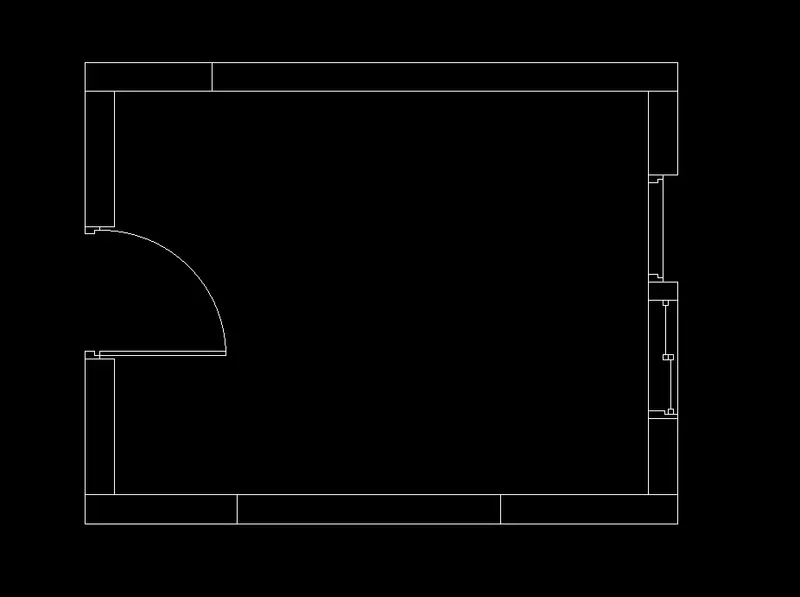
1. The drawing of walls and door is same as Below counter plan
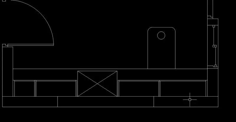
2. The snack counter is similar to below counter plan, the bottom most inner horizontal line in offsetted to 350 in upward direction, and then to 20 in downward direction.
The vertical right wall is breaked by using breakatpoint and is offseted in left direction to a distances of 35, 1010, 900, 900, 900, 450 and the inner vertical walls are offsetted by 20 on both sides
The inner 900 vertical panel is increased to 200 above using line command
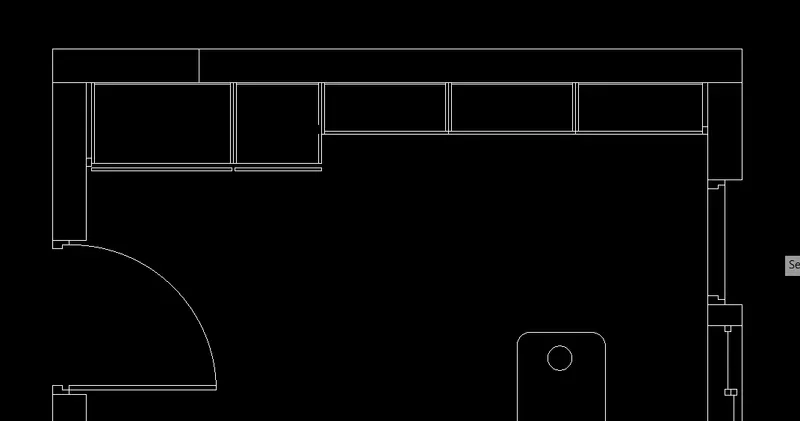
3.The inner top horizontal line is offsetted to 350 in downward direction and that line is offsetted in upward direction by distances of 20
The right vertical inner wall is breaked at 350 and offsetted in left direction to a distances of 35, 865, 865 ,865
Next the inner vertical wall height increased to 600 and offsetted in left direction to 600, 965 and 35
And the inner vertical lines are offsetted by 20 on both sides, and offset the inner top horizontal line is offsetted to 5 in downward direction
And using Trim, remove the unnecessary lines carefully.
4. Mark the dimensions using Dimlinear and write the text at required place the used font style is Times New Roman Greek and font size is 150 and 100
Using Hatch command, hatch the thickness of walls
4. Aim: To sketch the given column details as shownand to insert dimensions and text using Autocad software
Steps:
1.Open new file in Autocad 2023, Type UNITS, use Architectural and take Inches
2. Then LIMITS, Limits of lower left corner give (0,0) and limits of upper right corner (100',100')
3. Go to Tables in the annotation panel and create a Table with No.of Columns 3 and total No.of Rows are 4 ( take all rows as Data type) and we get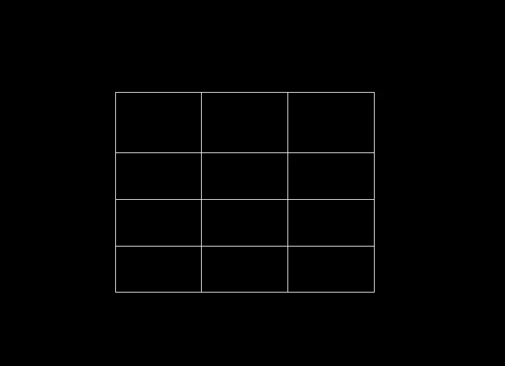
4. Select the 2nd and column first rows and click ok Merge All the select the last row in 3 columns and click Merge All, then we get our required table format.
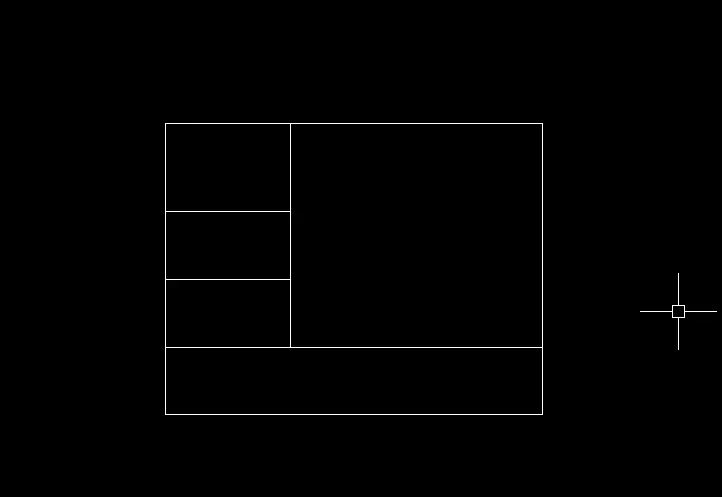
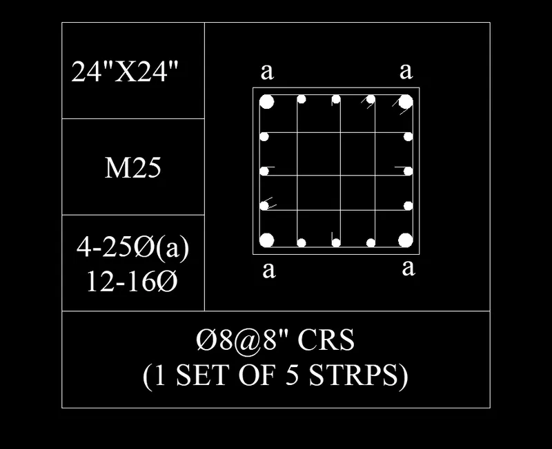
5. To create the reinforcement details as per 1st table, as per given cross section is 24"X24"
So create a sqaure of 24"X24" using rectangle command and Offset the square in inward direction by 1"
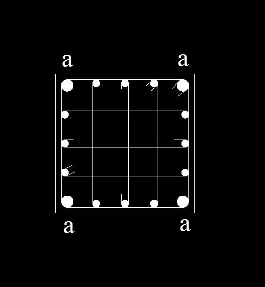
As per the reinforcement is 4-25mm dia bars and 12-16mm dia bars (25mm= 1inch and 16mm=0.62inch) by using same dimensions draw circles and place the 25mm bars at corners and 16mm in between at equal interval
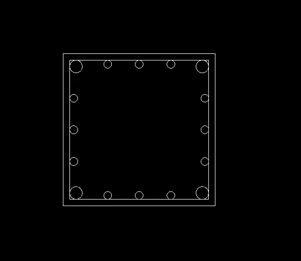
6.Using Line draw the reinforcement and using Hatch, hatch inside the circles and use Mtext to write text
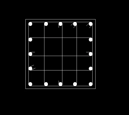
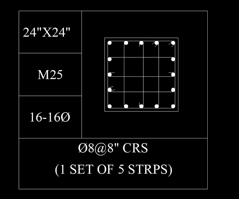
7. Similarly draw the reinforcement details of 2nd table and provide 16-16mm dia bars as shown
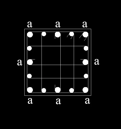
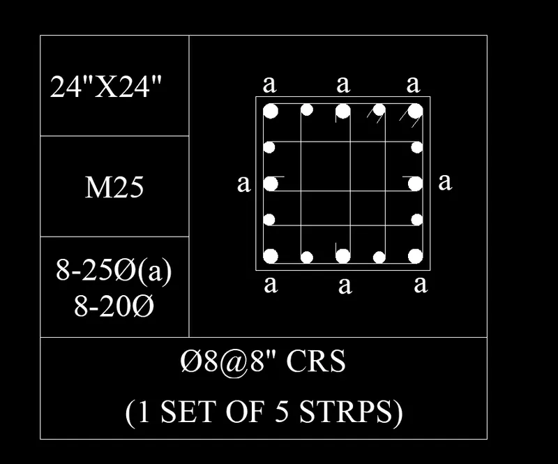
8. Similarly draw the reinforcement details of 3rd table and provide 8-25mm dia bars and 8-20mm dia bars as shown
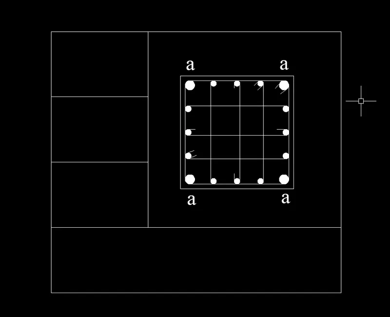
9. Place the reinforcement in the tables as given and adjust the table by clicking on table and draging
10. Using Text height as 3" and font style is Times New Roman Greek, and write text by double clicking on the cell
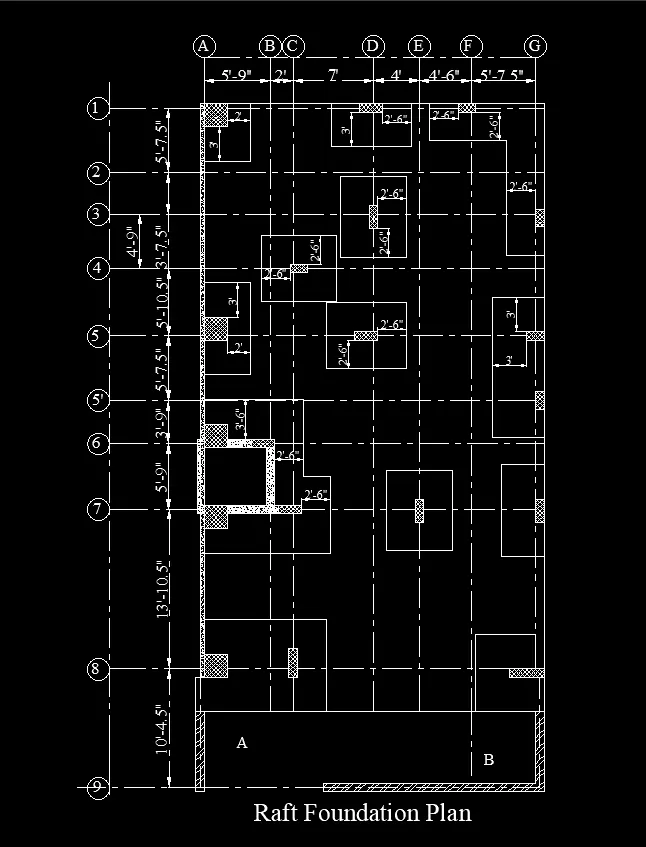
5. Aim: To draw the Raft Layout as shown in the Figure using Autocad software
Steps:
1.Open new file in Autocad 2023, Type UNITS, use Architectural and take Inches
2. Then LIMITS, Limits of lower left corner give (0,0) and limits of upper right corner (100',100')
3. Import the given pdf to Autocad and use Scale command to adjust to our drawing page
4. Take Line command and draw 30' in X direction then 60' in Y then 30, in -X and 60' in -Y direction
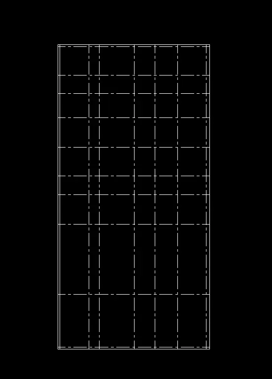
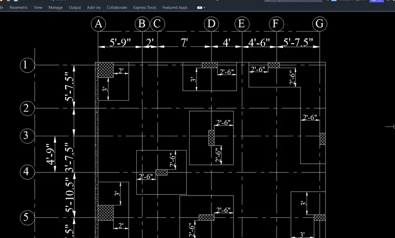
5. Using Offset, offset the veritcal left line in right direction by a distances of 4.5", 5'9", 2', 7', 4', 4'6" and 5'7.5" and again Offset the top horizontal line in downward direction by 4.5", 5'7.5", 3'7.5", 4'9", 5'10.5", 5'7.5", 3'9", 5'9", 13'10.5" and 10'4.5"
The offsetted lines both horizontal and vertical are changed to dotted lines
6. The column sizes are 24"X24" , 9"X24" and 9"X18"
Now place the 24"X24" column at the left top corner of offsetted line and draw lines from that column which are at 2' in horizontal and 3' in vertical
Then at section D column of 24"X9" is placed such that the right vertical of column is at distance of 9.5" from section D and draw the column, then from Column edges draw lines which are at 2'6" in horizontal and 3' in vertical
Then at section F column of 18"X9" is placed such that the right vertical of column is at distance of 4.5" from section F and draw the column, then from Column edges draw lines which are at 2'6" in horizontal and 2'6" in vertical
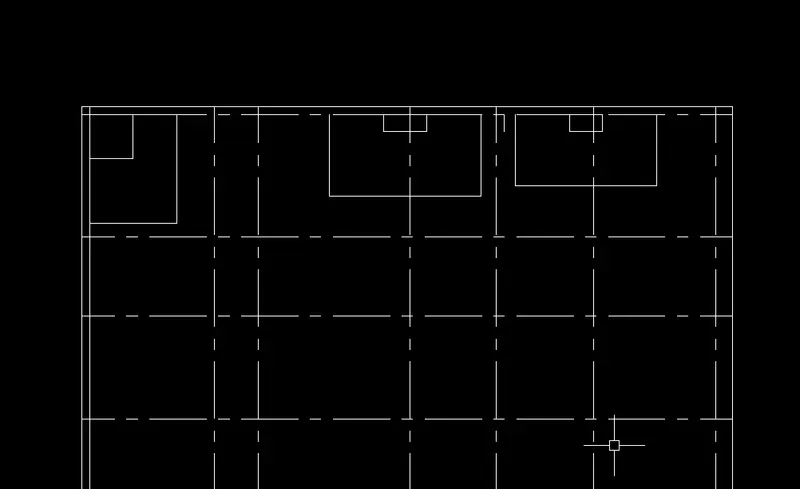
7.The column after section G and at section 3 column of 9"X18" is placed such that the top horizontal of column is at distance of 4.5" from section 2 and by that draw the column, then from Column edges draw lines which are at 2'6" in horizontal and 2'6" in vertical and then extend lines so to meet the lines of section F column
Then the column 9"X24" is placed at intersection point of section D and section 3, it placed in a way that is at 4.5" from section D on both sides and the top horizontal line is at 9" from section 3 and bottom line is at 15" from section 3 draw column, then from Column edges draw lines which are at 2'6" in horizontal and 2'6" in vertical .
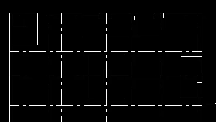
8.A column of 18"X9" is placed at junction of section 4 and section C, the left vertical is at 3" from section C and the top horizontal is at 4.5" from section 4 by that draw column, then from Column edges draw lines which are at 2'6" in horizontal and 2'6" in vertical .
Then the column of 24"X24" is placed at junction section 5 and A, it is placed such that the left vertical wall is alingn to section A and bottom horizontal line is at 4.5" from section, then from Column edges draw lines which are at 2'6" in horizontal and 3' in vertical .
Then the column 24"X9" is placed at junction of section 5 and section D, the right vertical is at 4.5" from section D and the top horizontal is at 4.5" from section 5 by that draw column, then from Column edges draw lines which are at 2'6" in horizontal and 2'6" in vertical .
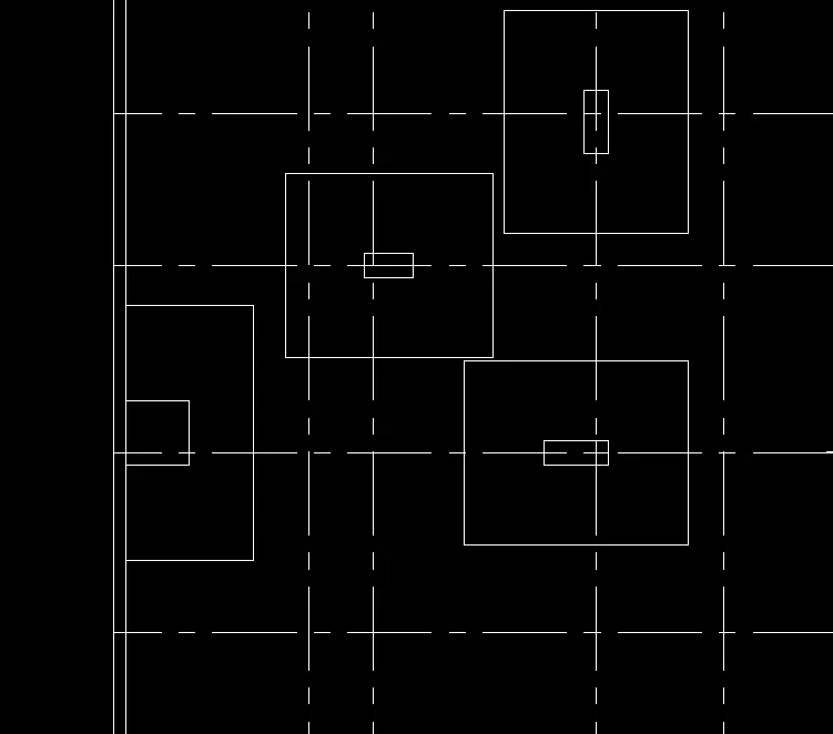
9. A column of 18"X9" is placed at junction of section 5 and section G, the left vertical is at 9" from section G and the top horizontal is at 4.5" from section 5 by that draw column, then from Column edges draw lines which are at 3' in horizontal and 3'in vertical.
A column of 9"X18" is placed at junction of section 5' and section G, the left vertical is aligned to section G and the top horizontal is at 9" from section 5' by that draw column, then from Column edges draw lines which are at 3' in horizontal and 2'6" in vertical and join the lines with upper column lines.
A column of 9"X24" is placed at junction of section 7 and section G, the left vertical is aligned to section G and the top horizontal is at 10.5" from section 7 by that draw column, then from Column edges draw lines which are at 3' in horizontal and 3' in vertical.
A column of 9"X24" is placed at junction of section 7 and section E, the left vertical is at 4.5" from section E and the top horizontal is at 10.5" from section 7 by that draw column, then from Column edges draw lines which are at 2'6" in horizontal and 2'6" in vertical.
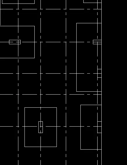
10.A column of 24"X24" is placed at junction of section 6 and section A, the left vertical is aligned to section A and the bottom horizontal is at 4.5" from section 6
Then the column 24"X9" is placed at junction of section 6 and section B, the right vertical is at 4.5" from section B and the top horizontal is at 4.5" from section 6, then from Column edges draw lines which are at 2'6" in horizontal and 3' in vertical.
A column of 24"X24" is placed at junction of section 7 and section A, the left vertical is aligned to section A and the top horizontal is at 4.5" from section 7
Then the column 24"X9" is placed at junction of section 7 and section C, the right vertical is at 9" from section C and the top horizontal is at 4.5" from section 7, then from Column edges draw lines which are at 2'6" in horizontal and 3' in vertical.
The 9" thick wall is drawn in between 24"X9" and 24"X24" columns and join them.
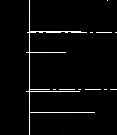
11.A column of 24"X24" is placed at junction of section 8 and section A, the left vertical is aligned to section A and the bottom horizontal is at 9" from section 8 then from Column edges draw lines which are at 3' in horizontal and 3' in vertical.
Then the column 9"X30" is placed at junction of section 8 and section C, the right vertical is at 4.5" from section C and the bottom horizontal is at 9" from section 8, then from Column edges draw lines which are at 2'6" in horizontal and 3' in vertical.
A column of 3'X9" is placed at junction of section 8 and section G, the right vertical is aligned to outer wall and the top horizontal is aligned to section 8, then from Column edges draw lines which are at 3' in horizontal and 3' in vertical.
And 9" thickness is provided of outer wall, and use Trim to remove extra lines
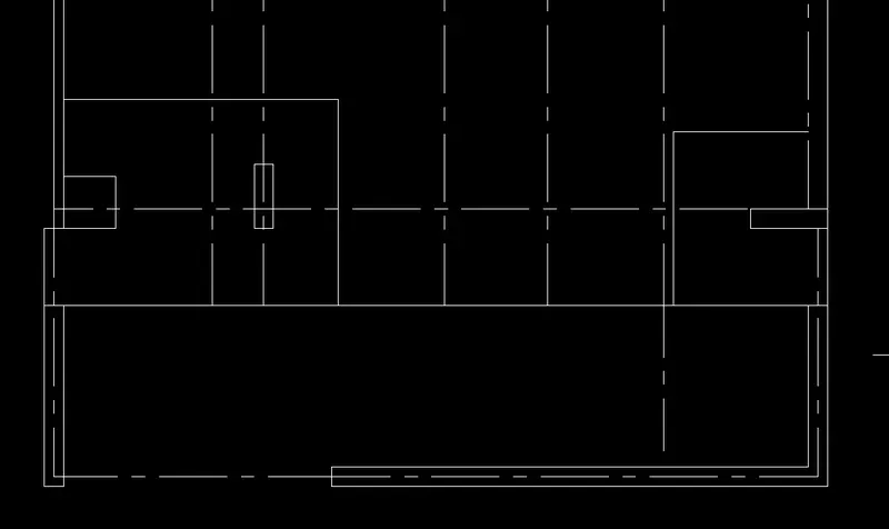
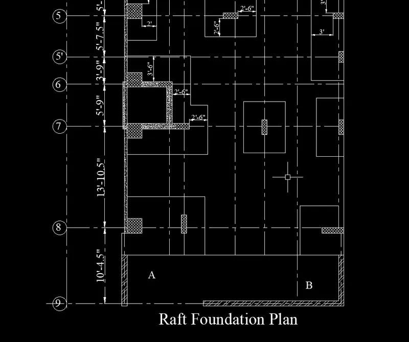
12. The entire Raft layout
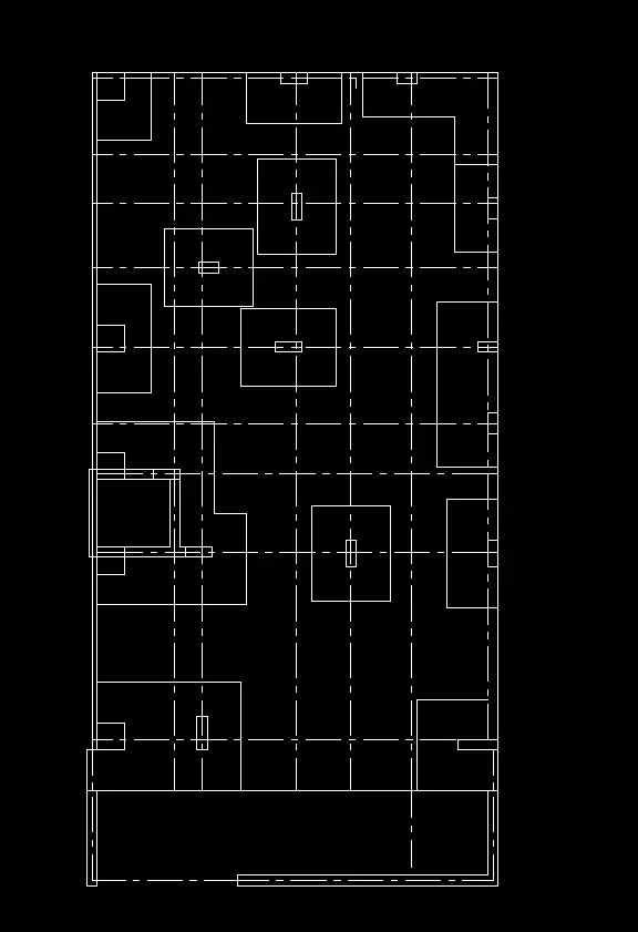
13.Mark the dimensions using Dimlinear and write the text at required place the used font style is Times New Roman Greek and font size is 1'
Using Hatch command, hatch the thickness of walls and columns
..