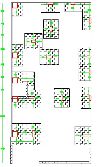
Creating a Wardrobe detailed drawing, Floor Plan, Kitchen Layout and Column Detail using AutoCad
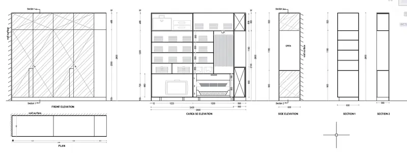
1. Draw the elevation and details of a wardrobe as shown in the Figure below. After sketching, you need to provide the dimensions and text with the use of layers. Use proper text styles and dimension methods to document it. Also, assume dimensions, wherever needed.
Note: All dimensions are in mm.
Units
Decimal with precision 0
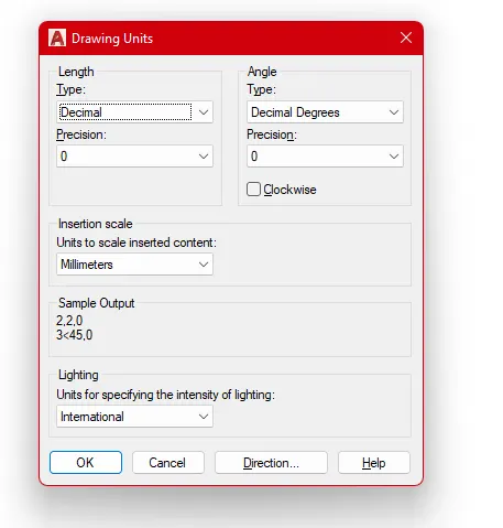
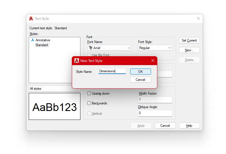
Set style for text and dimensions using command Style
Create a new style for Dimensions asDimensions.
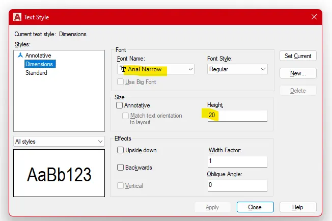
Font style with Arial Narrow Font and suitable height.
Create a new Dimension style
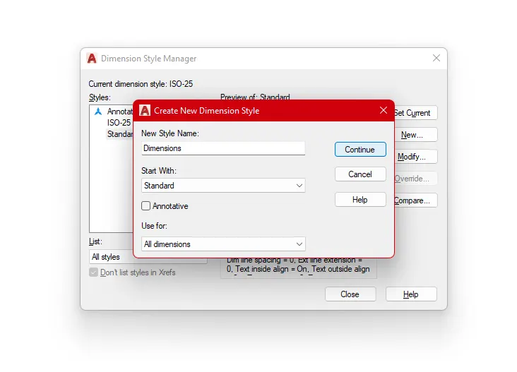
Set Settings for Text
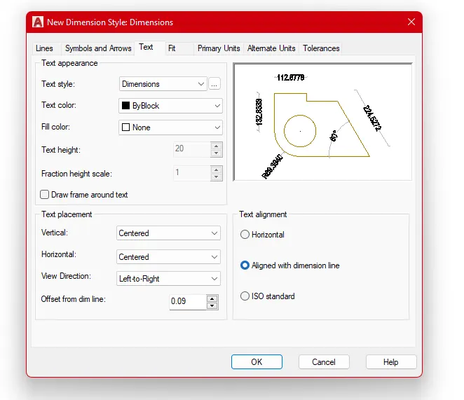
Set settings for Symbols and arrows
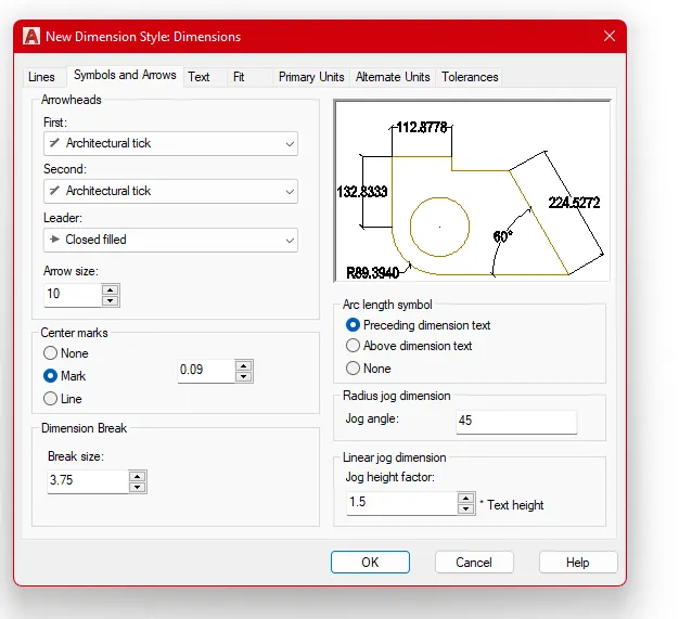
Set settings for Lines
Set settings for Primary units
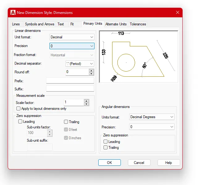
Make this dimension style as Current.
Set one more Style for Text
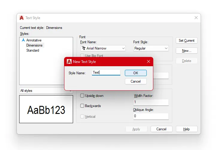
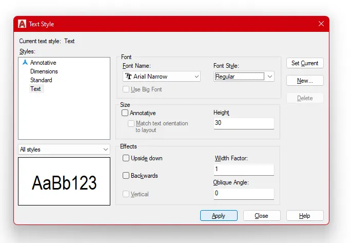
Set the Font style and height
Create a Layer for Dimensions and text by using the command LA
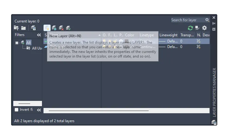
Create a new layer and names as dim and Text (Two layers)
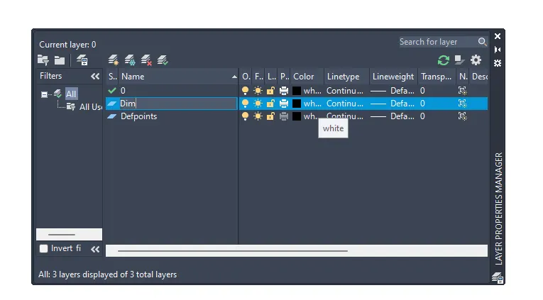
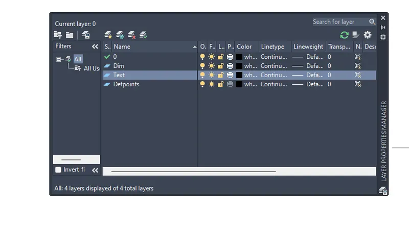
The current layer is set as 0
start the drawing with the Plan:
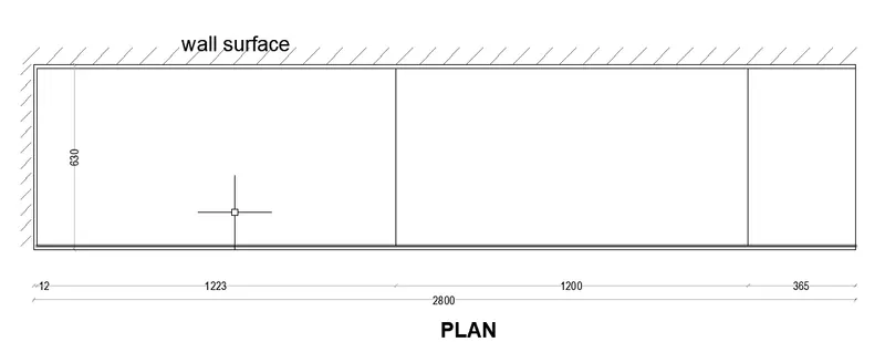
Its basically a rectangular in shape with 2 portions creating 3 compartments
The rectangle is created of dimensions 2800 mm x 630 mm
Draw the dimensions using dim linear and select the width and height of the lines drawn.
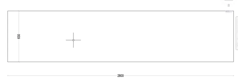
Move the dimensions to the dim layer
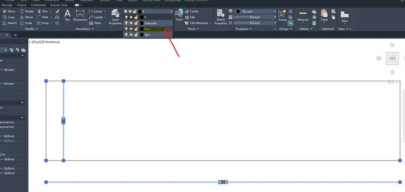
Create an offset 12 mm to inside to get the thickness of the wardrobe.
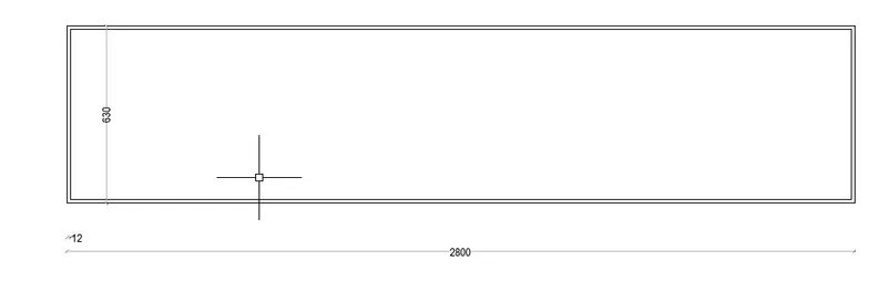
Create a partition at a distance of 1235 mm from the right known from carcase elevation. and another at 1200 mm from this partion.
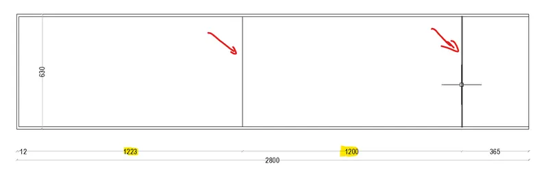
Draw a line with an angle of 45 besides the leftmost seperation
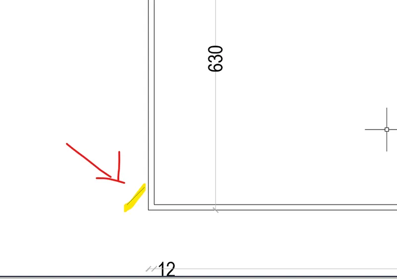
and give command array by selecting the line, select path and select the edge line to get the array of lines to create a wall surface.
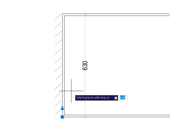
similarly, draw a line with an angle of 45 over the top of the wardrobe
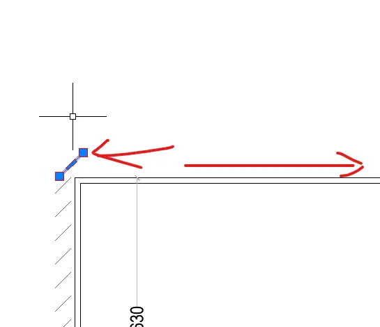
and give command array by selecting the line, select path and select the edge line to get the array of lines to create a wall surface.
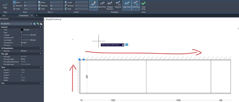
Create a text and write as wall surface and move to the layer Text.

Similarly the Heading as PLAN in the below
FOR CREATING A FRONT ELEVATION, CARCASE ELEVATION, SIDE ELEVATIONS & SECTIONS WE WILL DRAW A BASE LINE.
STARTING WITH FRONT ELEVATION
Draw a line 2600 mm vertical and 2800 mm horizontal line to get the outer line of the box.
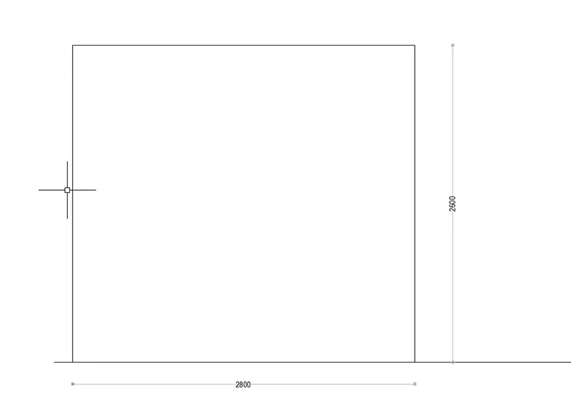
Create an offset 12 mm to get the wardrobe thickness
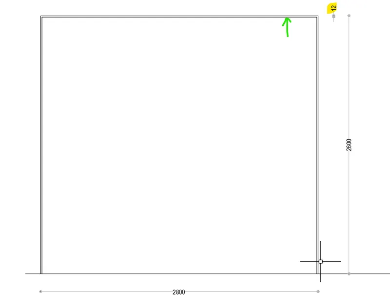
Create internal partiitons using offset and trim method and dimensions are mentioned
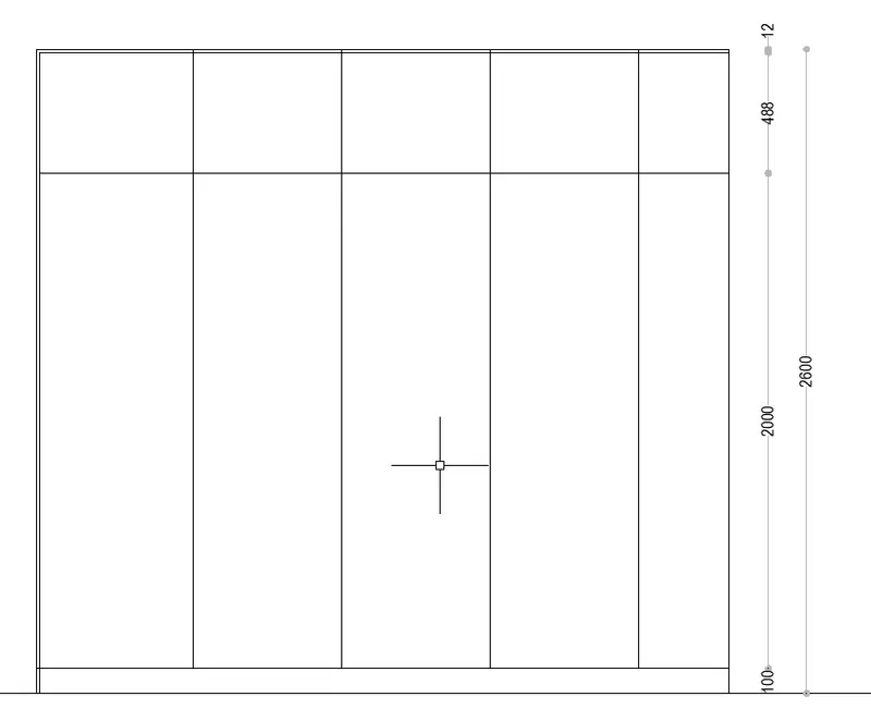
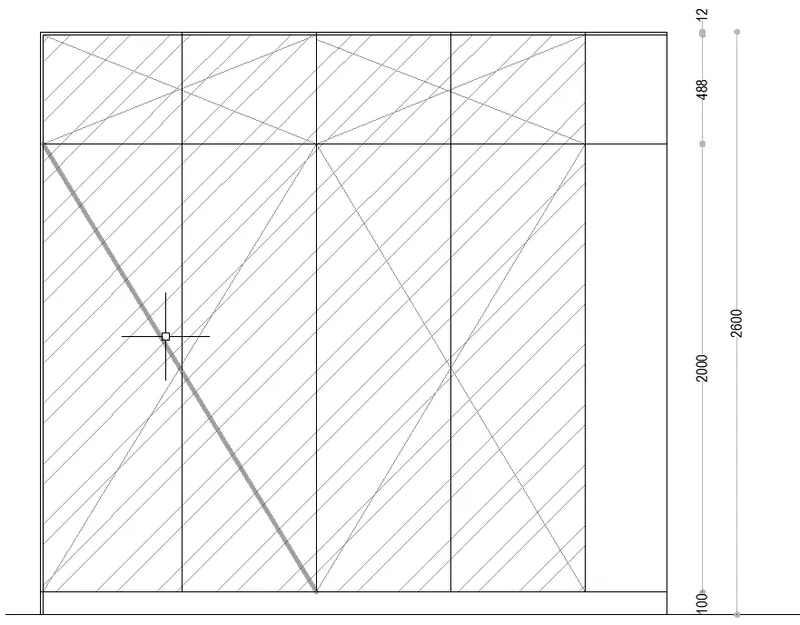
Hatch the portions and cross lines to differentiate the compartments.
Create a rectangle and small circle to show the door and lock provision on the door.
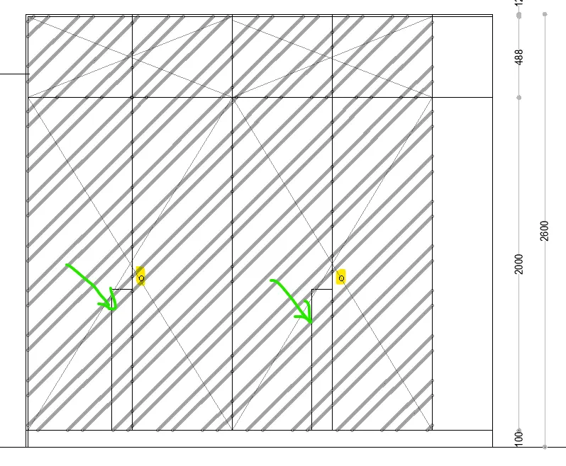
Draw the section 1 by leader option
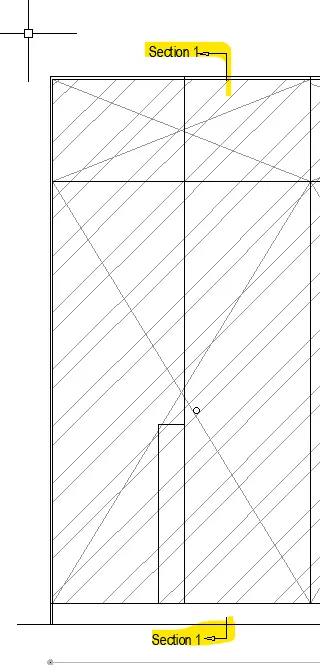
Draw a line with an angle of 45 besides the leftmost seperation
and give command array by selecting the line, select path and select the edge line to get the array of lines to create a wall surface.
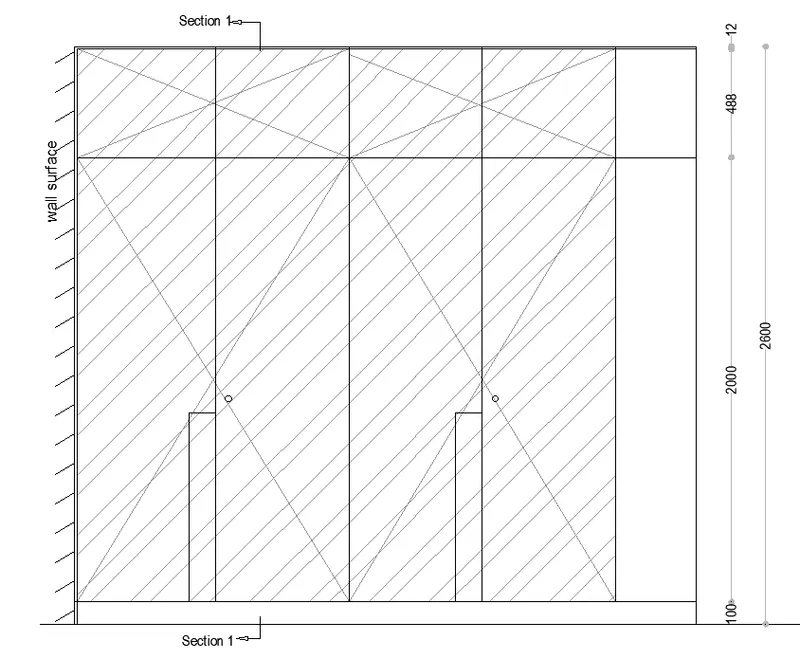
Front Elevation
Draw a rectangle with line command of 2800 mm x 2600 mm
Draw the thickness of the wardrobe outer side
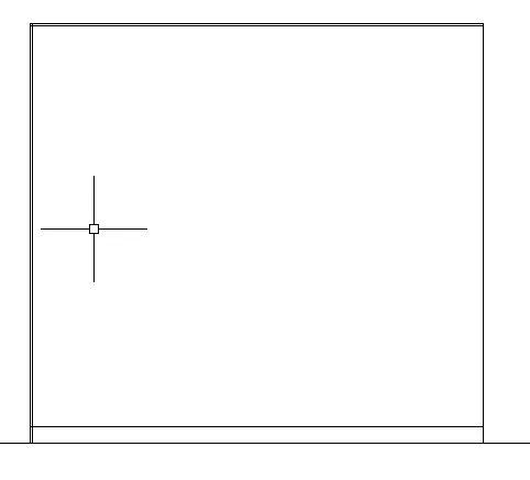
Draw the Partitions with offset commands & Draw the thickness for the wardrobe inner partitions.
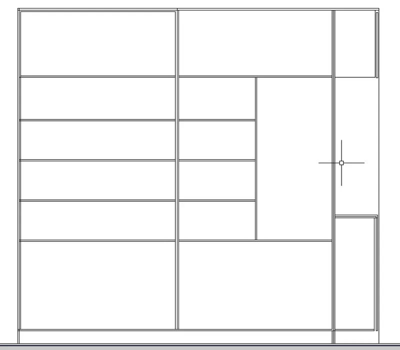
Draw the Cupboards below hanger space.
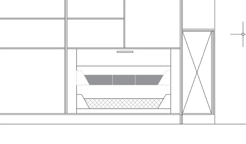
draw the rectangles as
Mention all the dimensions and text.
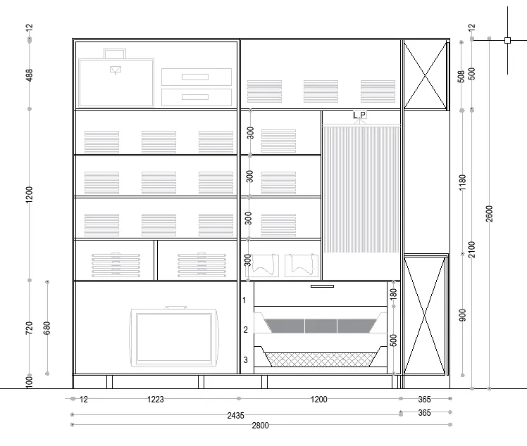
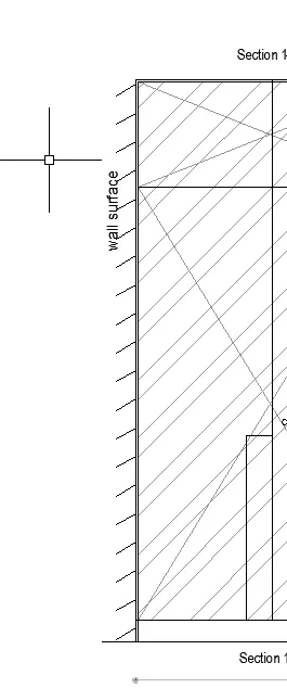
Side Elevation
Draw the outer border with Line command
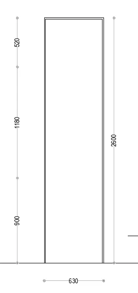
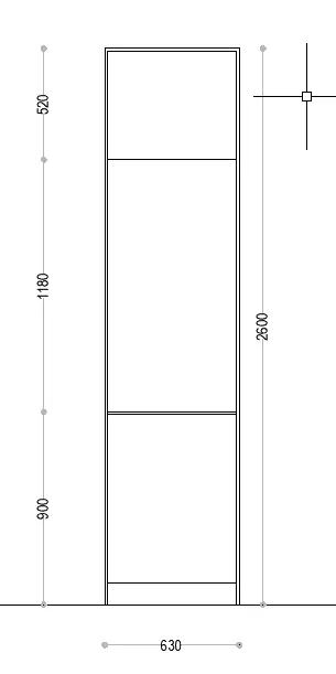
Draw the partitions
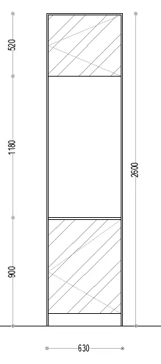
Draw the Hatching
Draw the wall surface on the right side of the dwg
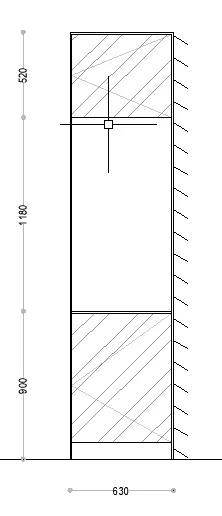
Draw all the Dimenisona nd text
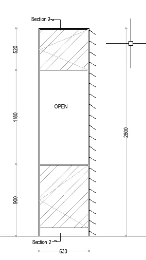
Section 1
Draw the outer border with Line command
Draw the partitions & Draw all the Dimenisons and text
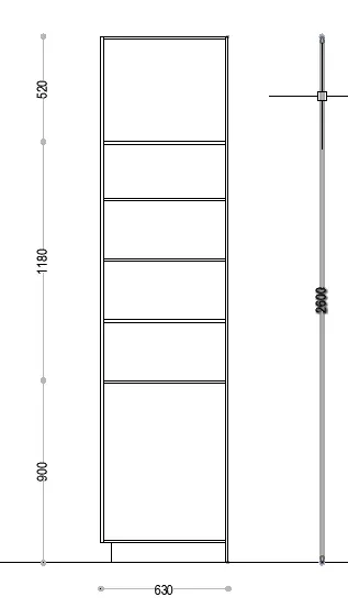
Section 2
Draw the outer border with Line command
Draw the partitions & Draw all the Dimenisons and text
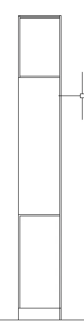
RESULT:
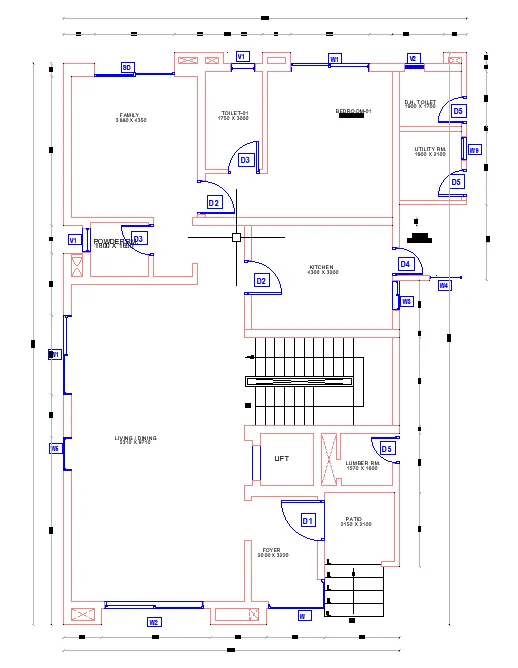
Q2. Draw the floor plan as shown in the Figure. Use the proper drafting tools to sketch the plan. Do not hatch or draw the furniture. You need to draw the floor plan with the following:
Note: You can also import the Floor_Plan.pdf into your current drawing and start working on the project. You need to scale the imported pdf file using reference option. All dimensions are in mm.
- Walls (Exterior and Interior)
Wall Thickness: Exterior Wall- 230mm, Interior Wall: 150 mm (Wherever Required)
- Doors and Windows: Assume the size of the doors and window.
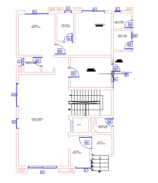
2.1 Stairs: Tread-300mm, Riser-150mm
- Insert Text wherever required
- Insert the dimensions using proper dimension techniques
Rooms:
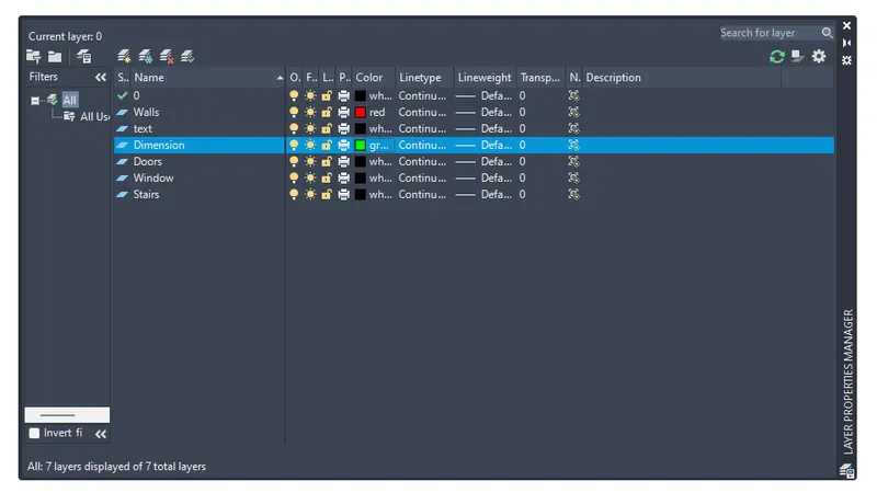
Create a Layer using LA command
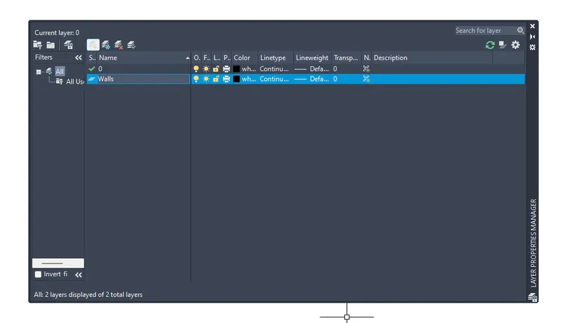
- Walls
- Text
- Dimension
- Doors
- Windows
- Stairs
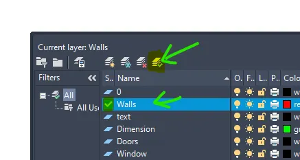
Set the Layer as Walls
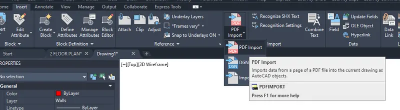
Insert PDF
Drawn a known measurement and by using align command, Scaled the pdf.
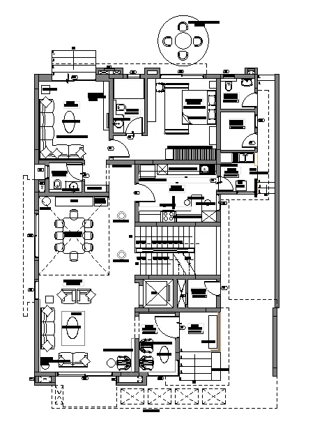
Now Drawing the Walls using osnap using line commands.
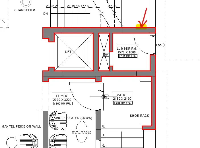
All the walls are drawn over the pdf by locking the PDF imported geometry lines.
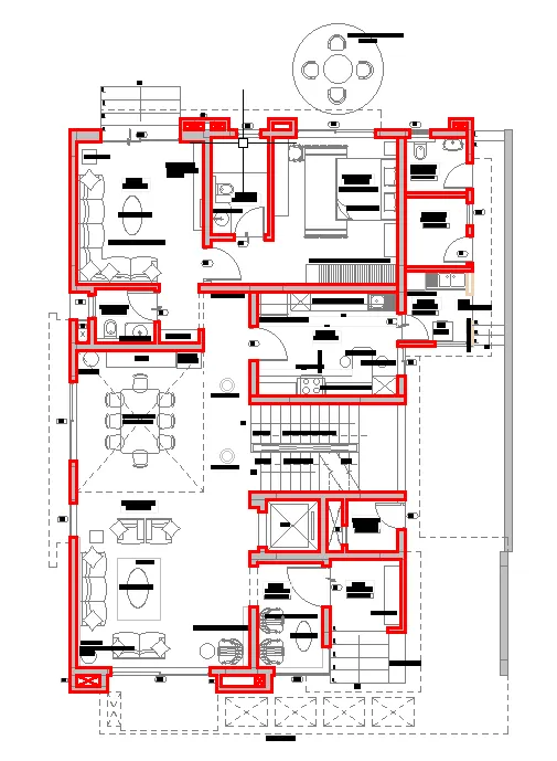
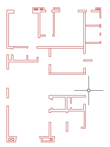
Walls are completed.
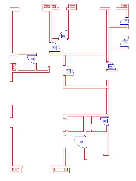
Doors
Set the Curent Layer as Door
And Draw the door overlay using arc,Line commands.
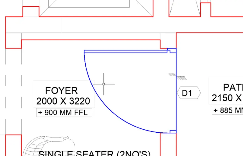
| DOOR NO | WIDTH | HEIGHT |
| D1 | 1230 | 2500 |
| D2 | 1050 | 2500 |
| D3 | 950 | 2500 |
| D4 | 850 | 2500 |
| D5 | 830 | 2500 |
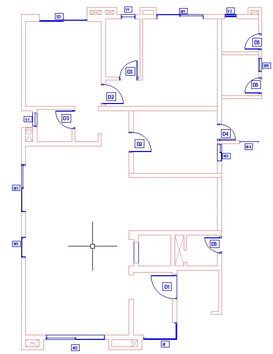
WINDOWS:
Draw Stairs and Insert Text
Dimensions:
Use "Dimlinear" and "Dimcontinue" to draw all the dimensions.
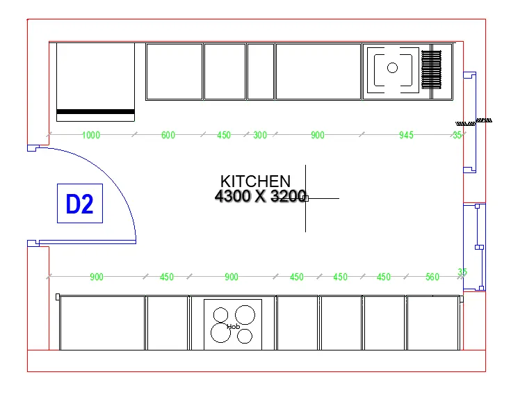
Q3. Create the Kitchen Layout as shown in the Figure below. Also, use proper dimension techniques to dimension the kitchen layout. Also, insert text wherever required. All dimensions are in mm.
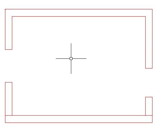
Draw the outer Walls and inner walls using Line command
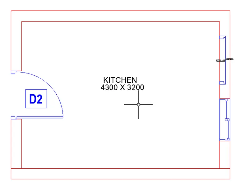
Draw Doors and Windows
Draw all the partitions using offset and line command
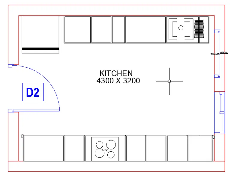
Draw all the dimensions with a setting a current layer as Dimensions, Use Dim linear and Dimco
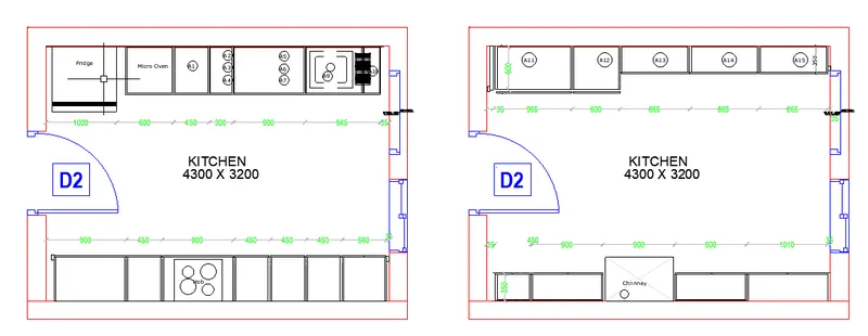
Simillarly we create the ABOVE COUNTER PLAN
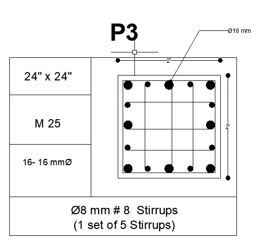
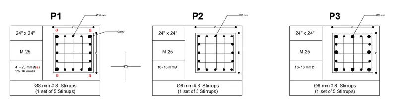
Q4. Sketch the column details as shown in Figure. Insert dimensions and text in the figure. Refer to the bar sizes from the schedule.
8mm ---- 0.31 Inches
25mm--- 1 inches
16mm—0.62 inches
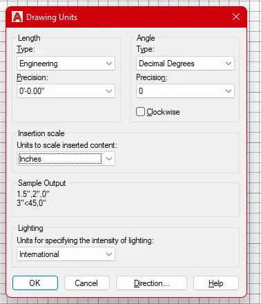
Set units to Engineering
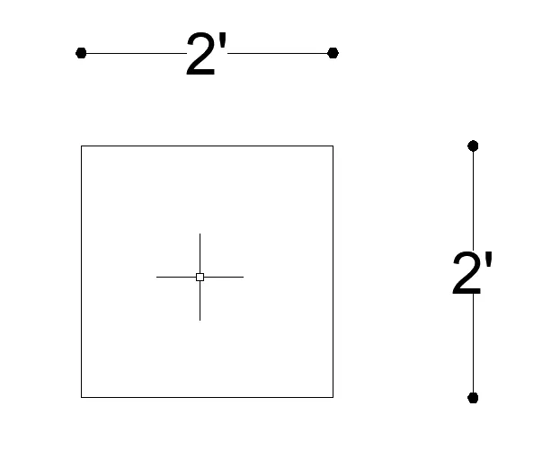
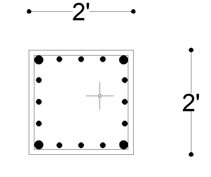
Draw the the column size as 24" x 24"
Draw the cover lines
Draw the Main Reinforcement of 25 mm dia on the four corners
Draw the Reinforcement of 16 mm dia of 3 nos on each face of total 12 No's
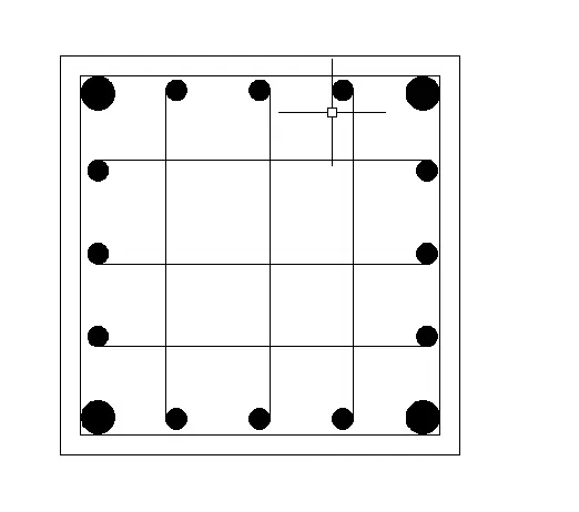
Draw the Stirrups by joining with Lines
Draw the boundary and partitions to write the text required to get the P1 details.
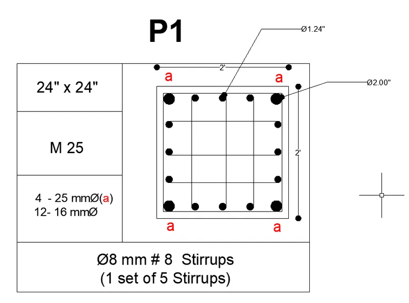
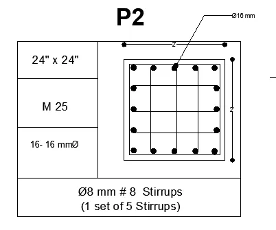
Simillarly copy paste the P1 to P2 & P3 and modify the required changes in text and Reinforcement details
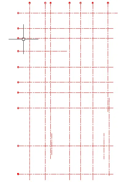
Q 5. Draw the Raft Layout as shown in the Figure. Assume the column size as per your knowledge. You can take the sizes as: 24”x24”, 9” x 24”, 9” x 18”, and 9’ x 24”. You can import the raft_foundation.pdf to ensure the missing dimensions.
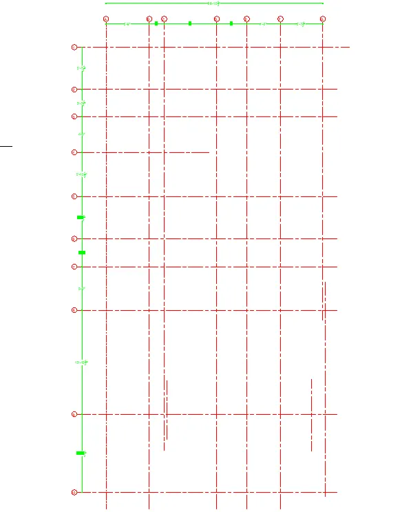
Draw the grid for the given diemnsions
GIve the dimensions
Draw the walls and seperations
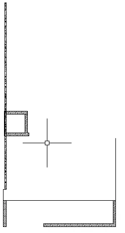
Draw the Columns of given sizes
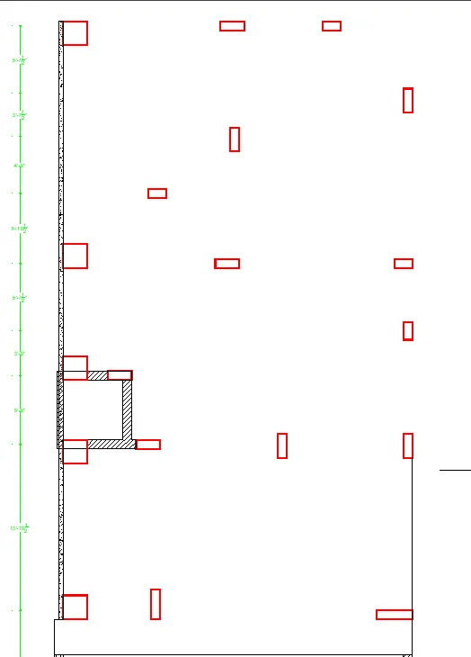
Draw the Footings and give dimensions of offset from the column to Footing faces.