Creating a Wardrobe detailed drawing, Floor Plan, Kitchen Layout and Column Detail using AutoCad
1. Draw the elevation and details of a wardrobe as shown in the Figure below. After sketching, you need to provide the dimensions and text with the use of layers. Use proper text styles and dimension methods to document it. Also, assume dimensions, wherever needed.
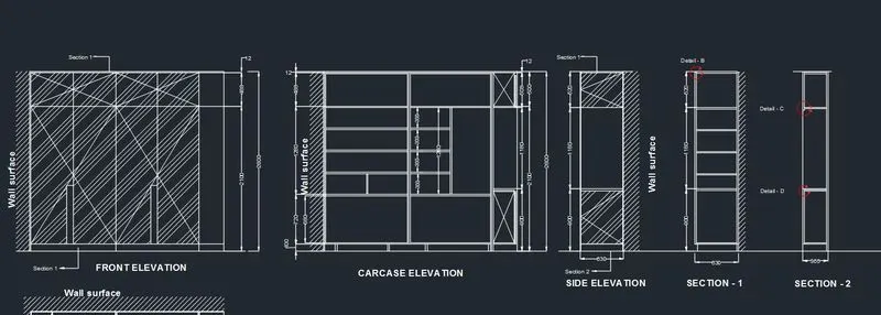
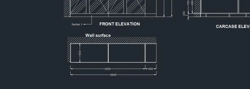
Aim: To draw the elevation and details of a wardrobe as shown in the Figure.
Introduction: The given figure consists of wardrobe details which contains front elevation, carcase elevation, side elevation and sections of the respective drawing. The given figure also consists of the top view of the plan.
Steps:
- Initially using the line tool and offset tool the top view of the drawing is drawn
- Using the Hatch command the sides of the plan are hatched to show the wall surface
- Then from that figure projection lines are drawn
- Using the projection line the front elevation figure is drawn as per the reuirements
- Then the side elevation and section drawings are drawn using the the given measurements with the help of line tool and offset tool
- Then using hatch command hatch is done wherever reuired.
- Then after completing the figure the dimensions are marked
- For marking the dimensions of the drawing initially, the dimension style and size of the dimensions are fixed in the dimenion style using the dimstyle command
- After fixing the right dimension style the dimensions of the figure are marked and the diagram is finished.
- In the section drawing dimbase command is used which is used for providing baseline dimensions.
Results: The given plan is drawn and also the dimensions of drawing are marked and various options of dimenions such as dimcontiue,dimbase which is used for continued dimensions are used and the usage of the dimensions are learnt.
2. Draw the floor plan as shown in the Figure. Use the proper drafting tools to sketch the plan. Do not hatch or draw the furniture. You need to draw the floor plan with the following:
Note: You can also import the Floor_Plan.pdf into your current drawing and start working on the project. You need to scale the imported pdf file using reference option. All dimensions are in mm.
- Walls (Exterior and Interior)
Wall Thickness: Exterior Wall- 230mm, Interior Wall: 150 mm (Wherever Required)
- Doors and Windows: Assume the size of the doors and window.
2.1 Stairs: Tread-300mm, Riser-150mm
- Insert Text wherever required
- Insert the dimensions using proper dimension techniques
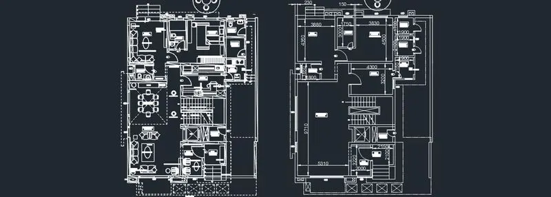
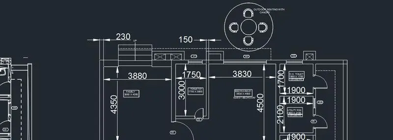
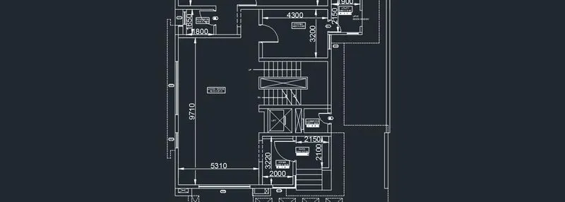
Aim: To draw and provide dimensons of the floor plan as shown in the Figure
Introduction: The given plan consists of a large living an dining room, bed rooms, stairs etc., The plan is given in the metric scale and provided with windows and doors information also. The plan is also provided size of the stairs and walls like external and internal walls.
Steps:
- Initially the drawing is imported into the autocad since the given file is pdf format.
- After the importation the drawing have to be scaled as it is not in the reuired scale
- The scaling is done by drawing a line of 230mm and from the scale option using reference option, the drawn 230mm line is used as a reference object and the whole plan is scaled
- After scaling the plan x lines are drawn for projection and the plan is created without hatch and with the dimensions given
- The given pdf is used as a reference and the plan is recreated
- After the plan is drawn and finished dimensions are marked
- For dimension marking the initial setting is to fix the dimension style,
- The dimension style of the plan is set using the dimstyle command
- After setting the dimension style,the dimensions of the plan are marked
- During the dimension marking some of the dimensions were overlapping with each other. In order to avoid the overlapping dimbreak command was used which breaks the lines of the dimension overlapping each other
- After that using mtext option the texts inside the plan are written and the diagram is finished.
Results: The given plan is imported,scaled and recreated. Usage of scaling option with reference to the object is done and learnt. The other options of dimensions such as dimbreak are used and learnt.
Q3. Create the Kitchen Layout as shown in the Figure below. Also, use proper dimension techniques to dimension the kitchen layout. Also, insert text wherever required. All dimensions are in mm.
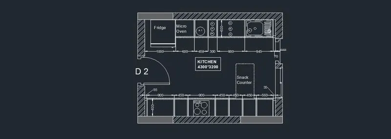
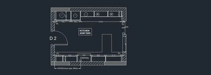
Aim: To create the Kitchen Layout and provide dimensions as shown in the figure.
Introduction: The given kitchen layout consists of two plan given. The plan also consists of hatch and other kitchen utilities such as chimney etc., The given plan is recreated using the dimension given.
Steps:
- Initially a rectangle of the given dimension is created
- The 2nd step is to do offset of the rectangle to provide thickness of the wall which is to 230mm.
- After that openings are provided for door and ventilation
- Then as per the dimension given the utilities of the kitchen are drawn using the offset option
- The hatching of the wall are done using the hatch command
- Then the dimension are marked after setting the dimension style.
- In this plan the dimensions are marked continuously using the command dimcontinue
- The dimcontinue command is used the provide the dimensions continuously from one point to another
- Then using the mtext option the utilities, and title of the kitched are written and the diagram is finished.
Results: The given kitchen plan has been drawn, hatched and dimensions are marked and different tools of dimension are used wherever required.
Q4. Sketch the column details as shown in Figure. Insert dimensions and text in the figure. Refer to the bar sizes from the schedule.
8mm ---- 0.31 Inches
25mm--- 1 inches
16mm—0.62 inches
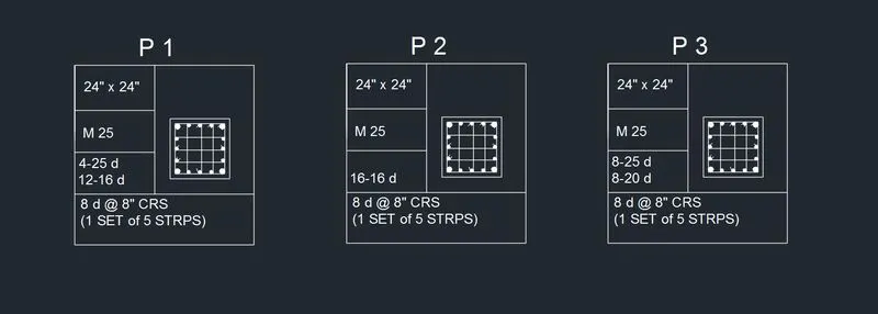
Aim: To sketch the column details as shown in figure and insert text information about the columns namely column schedule.
Introduction: The given diagram is a column schedule which contains details about the columns such as size, mix, reinforcement details, stirrup details and marking of the column. It is provided in order to provide a clear details of the columns which can be easily understood at the site.
Steps:
- Initially a rectangle of 24"x24" is drawn and a offset of 1" is done.
- Then as per the given size of reinforcement bars which is 8mm -0.31 Inches, 25mm- 1 inches, 16mm-0.62 inches are drawn.
- Then the bars are copied and placed inside the columns as per the placement given in the diagram.
- Then a large rectangle is drawn and the columns are placed inside and table is designed using the line tool with 4 rows and two columns to provide details
- Then using the Mtext command the detsils of the column such as size,mix and reinforcement details are provided.
- Finally the marking for the columns are provided namely P1,P2 and P3.
Results: The given column schedule is drawn with the details and using the mtext command the details are listed out.
Q 5. Draw the Raft Layout as shown in the Figure. Assume the column size as per your knowledge. You can take the sizes as: 24”x24”, 9” x 24”, 9” x 18”, and 9’ x 24”. You can import the raft_foundation.pdf to ensure the missing dimensions.


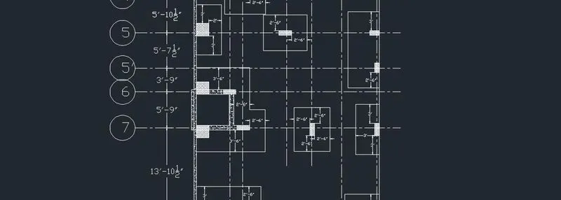
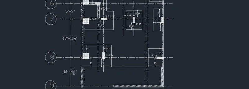
Aim: To draw the Raft layout as shown in the figure and provide markings,dimesnions of the footings with the columns.
Introduction: The given figure is a raft foundation layout of the plan with the details of the footing sizes as per the column placement with respect to the centre line markings . It is also provided with details of r/w of 4.5" and 9" wall. The given figure is one of the mandatory drawings to be provided to the site for the laying of foundation.
Steps:
- For this raft foundation layout four types of columns are provided with the sizes of 24”x24”, 9” x 24”, 9” x 18”, and 9’ x 24”. In order to place the columns initially the columns of given sizes are drawn and converted into blocks.
- The blocks are named after the size of the columns are saved.
- Then the centre lines are drawn using the line and offset tool to provide accurate dimensions.
- Then the lines are convereted into centrelines by converting the linetype from continuous to centreline which is given the command table of the linetype.
- Then the columns are inserted wherever using the insert command as the blocks are already drawn and saved.
- After the placement the columns are hatched as per the figure.
- Then to provide markings of numbers and alphabets in vertical and horizontal respectively a 2 cirles are drawn.
- Further using the Attdef comand attributes are designated and given tag and default values then placed inside the circle.
- Then both are coverted into blocks and inserted in both horizontal and vertical directions.
- The different markings are provided using the defined attributes.
- Then as per the dimensions given the raft foundation is drawn offseting from each column.
- Then from the marked G line offset of 9" is done to provide the walls and from A line offset of 4.5" is done to provide the retaining wall.
- Then the walls are hatched using hatch tool as per the figure.
- Finally after setting the dimension style the dimension are marked and the diagram is finished.
Results: The given raft foundation layout is drawn and the usage of tools such as blocks and attributes are used and various of tools of dimension such as dimcontinue is used. The block and attributes tools are less time consuming as the text such as markings can be provided easily.