Creating a Wardrobe detailed drawing, Floor Plan, Kitchen Layout and Column Detail using AutoCad
CHALLENGE – 6
AIM – In these challenges we know about the dimension and how can I work in dimension of the whole project and I can learn about the properties of the dimension and uses the different dimension at different section and the layer of dimension.
PROCEDURE:
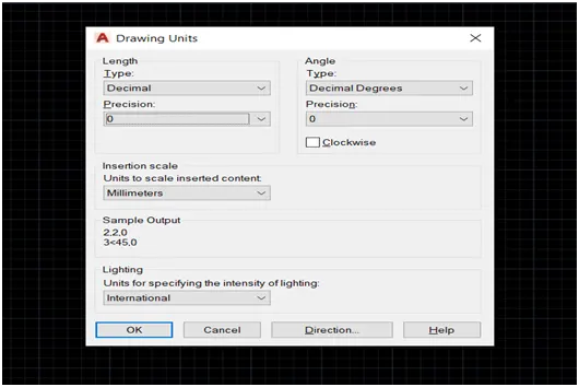
1.Open the auto cad and set the unit with unit command and choose the unit in mm
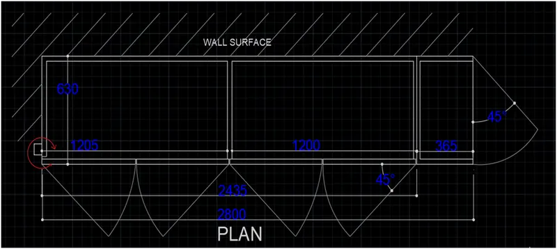
2.First we crearte a plasn , create a outer line which is dimension 2800 mm , 630 mm through line command then go for offset and offset a wall the thickness is 30 then the vertical lines offset frome right to left 365mm,1200mm, 30mm, 1205mm then thrm the edges or intersection point then go the mid point if the rooms and creat the door simble then go the the left corrner and create the cut on wdges as shown in figure and draw the box and place the above the cut adge then create a arc and show the arrow and define the layer then create the surface of the hatch area through the polyline command and hatch the area then delete the surface then go for the text command and get the name then go for the dimstyle and set the dimension setting and show the dimensonof the plane.
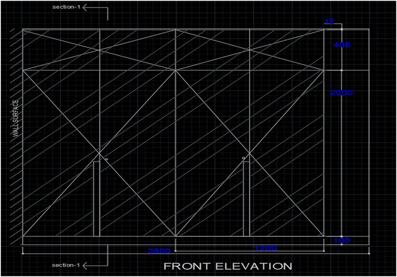
3.After the create a plane go through the front elevation create a line 2800mm through line command and go for the offset and offset the 100mm, 2000mm, 488mm, 12mm as shown in figure then join the vertical line both end through line command then go for offset and offset the 1200mm right to left then create the line at mid point for both boxes then create the both mid line 900mm, door symbol the go the polyline and create a surface for hatch area then hatch the area then delete the surface area then create a section line as shown in figure through the line command then go for the text command and give the name then go for the dimension command and give the dimension of the drawing.
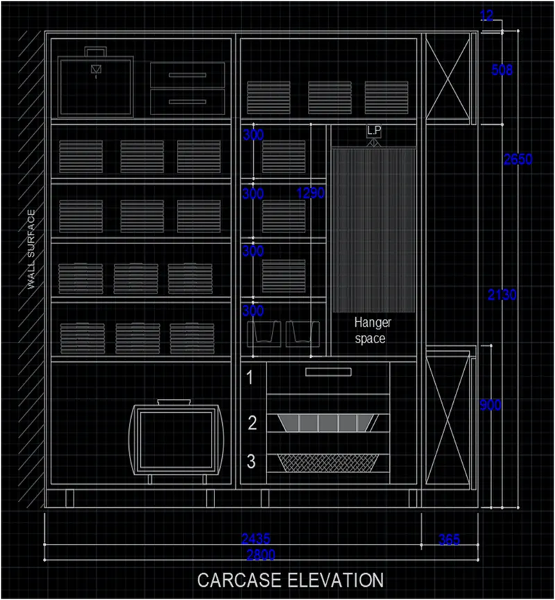
4.After creating a front elevation go to the carcase elevation create a line 2800mm then go for offset command and offset 100mm,30mm, 680mm 30mm, 300mm, 30mm, 300mm, 30mm, 300mm, 30mm, 300mm, 30mm, 508mma at previous line and 12mm then create a vertical line on both side then go for offset command and offset left to right 12mm, 30mm, 12mm 365mm to end line and 30mm of both side on 365mm offset line then 1200mm on same line then 30mm then go for the left end ad offset 12mm, 30mm. then go for the trim command and trim the corner edges and the intersection points as shown in figure then right end two boxes of both end create the diagonal line then create a box 50,100 four boxes and place the above first horizontal line as shown in figure then create a different place the inner component of the drawing which is through the line command, offset command , mirror command, etc. then create a group of the component and place the places as given place then create a surface through the polyline command for the wall surface hatch and delete the surface then go for the text command and give the name then go for the dimension command and give the dimension of the drawing.
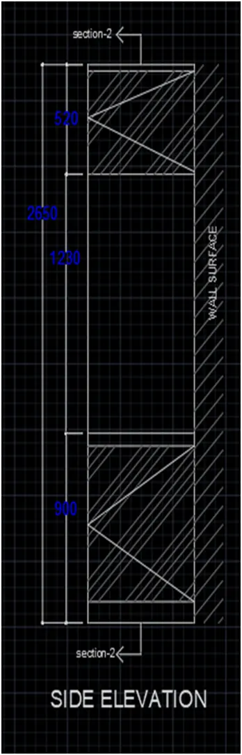
5.After create a carcase elevation go for the side elevation create a line 630mm then go for offset command and offset 100mm, 770mm, 30mm, 1230mm,508mm, 12mm then join the vertical line both end then create a triangle or v shape from diagonal line corner to center same as both boxes then create a section line and give the name of the drawing from text command then create a wall surface through the polyline command and hatch command then delete the surface then give the dimension of the drawing.
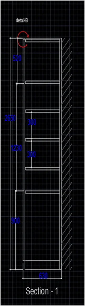
6.After create a side elevation go for the section- 1 create a line 630mm then go for offset command and offset 100mm, 770mm, 30mm, 1230mm,508mm, 12mm then offset above to below offset from above 520mm down word side 300mm and up word side 30mm same line then below 300mm,30mm 300mm, 30mm, 300mm, 30mm then trim the corner edges and intersection point then create a cut for above left side as shown in figure then create a surface wall through the polyline command and hatch command then delete the surface the go for the text command and give the specific name then go for the dimension command and give the dimension of the drawing.
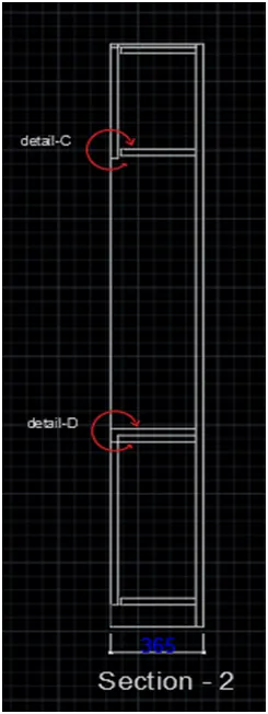
7.After create a section-1 go for the section- 2 create a line 365mm then go for offset command and offset 100mm,30mm. 740mm, 30mm, 1230mm,508mm, 12mm then trim the edges or intersection points then cut the above corner at both end then create a arc and show the direction as shown in figure select this arcs and get layer from layer command and get the color then go for the text command and give the name then show the dimension of the drawing.
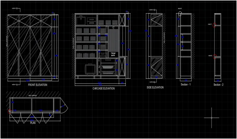
RESULT: Create the all drawing with mention the details and use the layer command of this drawing and set the settings of the dimensions and use the different pattern and dimension in this drawing.
FLOOR PLAN
AIM : To create a floor plan With mention all dimension and Place the components of the drawing and give the Complete the details of the drawing.
PROCEDURE:
1.Open the auto cad and set the unit with unit command and choose the unit in mm
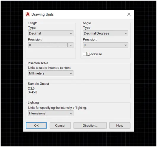
2.First we create a horizontal line 5310mm and vertical line 9710mm on both side and join the other end then go for the offset and offset 230mm wall thickness all side then create a foyer offset the line 2000mm and 230mm join the line through line command then go for the offset vertical 230mm and 3220mm, 230mm then create a line continue the both upper line 2150 mm and offset 2100 mm,150mm then join the inner both line and again offset 150mm horizontally then fillet at radius 0mm both side then offset upper side 1600mm and 230mm then stretch the line at hall wall then go for the hall powder room(because the stair dimension are not given) first create the air pass wall 1650mm long then go for offset 230mm,330mm,230mm,1800mm,150mm then join the line and offset upward 150mm, and stretch 7560mm then continue create a line 4500mm the go for offset horizontally left side 230mm,3830mm,150mm,1750mm,150mm,3880mm,230mm then join the line and offset up ward 230mm then go for the D.H. Toilet offset a line right side 1900mm, 150mm Then join the line and go offset down ward 230mm,1700mm,150mm,2100mm,150mm,2150mm then join the line then go for the kitchen create a line from bedroom-1 3200mm then offset left side 230mm, 4300mm,230mm then create a stair 300mm trade and 150mm riser after the completion outline of the drawing go for the trim option and trim all the intersection point of the all wall then create a door, windows, ventilation then create a cantilever to the dash line then completion of the plan go for the component of the drawing and place the correct places of the component after the placing of component go for the detail or name of the objects use for the text command then go for the dimension command and give the dimension of the drawing.
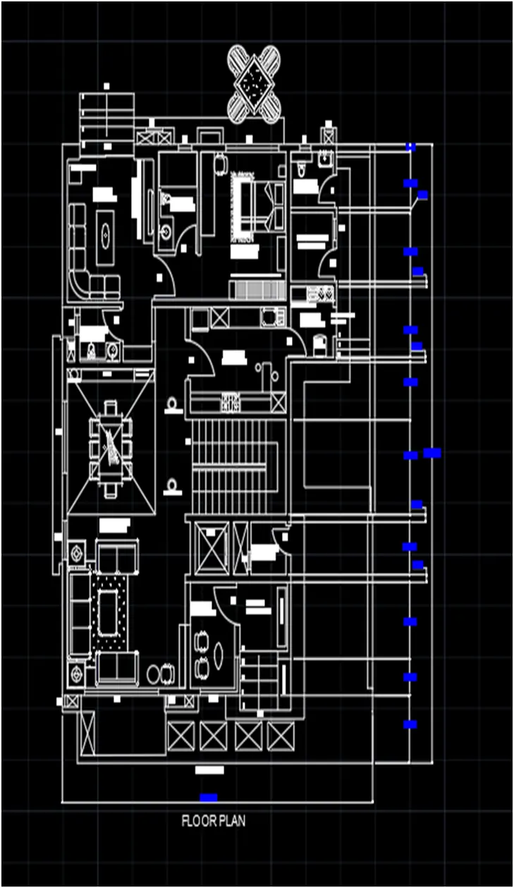
RESULT: I am creating the plan successfully of this floor plan and place the components with dc-enter command and mention the all dimensions of the drawing.
KITCHEN PLAN
AIM: To create a kitchen with their components and their specifications with mention proper dimensions.
PROCRDURE:
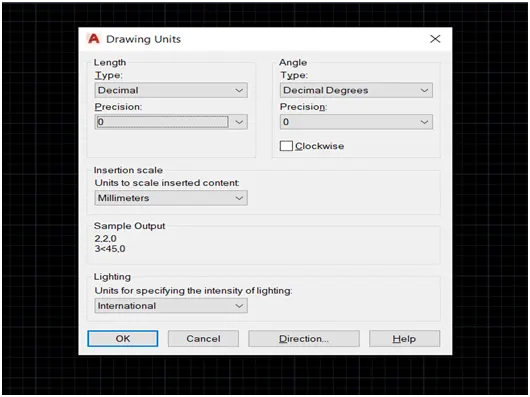
1.Open the auto cad and set the unit with unit command and choose the unit in mm
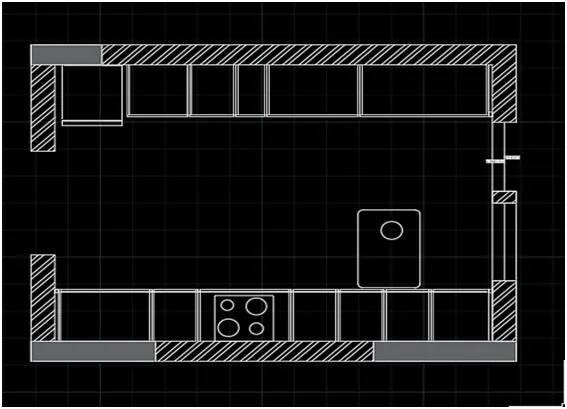
2.First create a box 4230,3200 mm
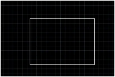
3.Then go for offset 230mm for exterior wall
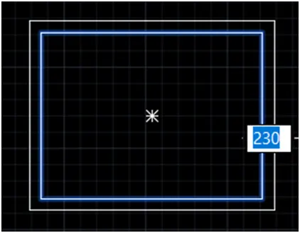
4.Create a line midpoint as shown in figure
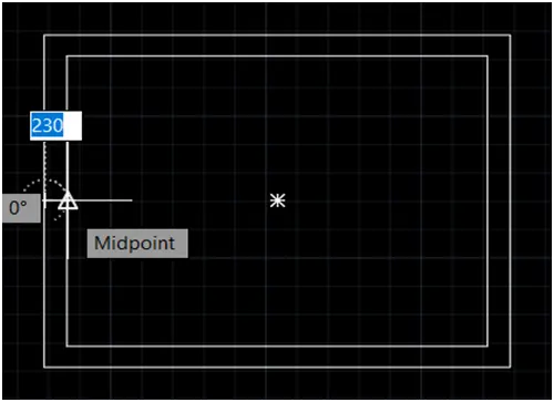
5.Go for offset 600mm both side
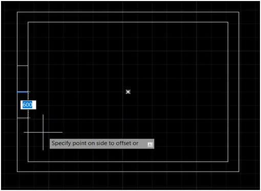
6.Then trim that portion as shown in figure
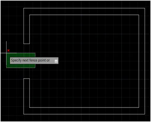
7.Create a window from midpoint 900mm
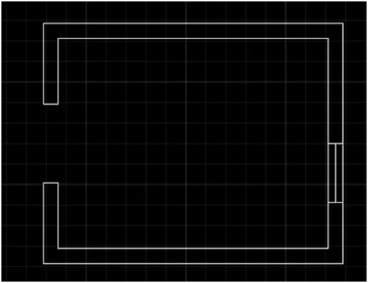
8.create a overlap line as shown in figure
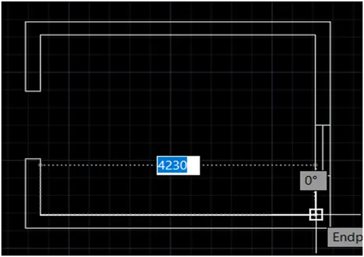
9.Then move the line 600mm up word
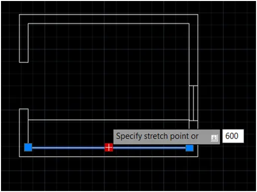
10.Again draw the overlap line 600mm as shown in figure
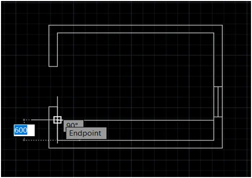
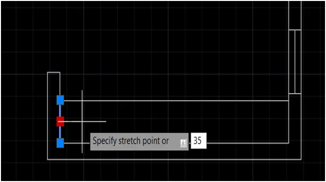
11.Then move the line 35 mm right sides
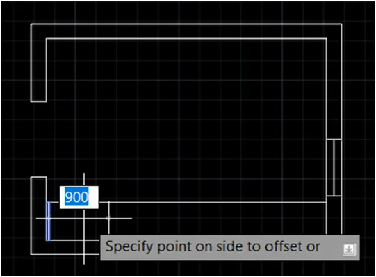
12.Then go for the offset 900mm
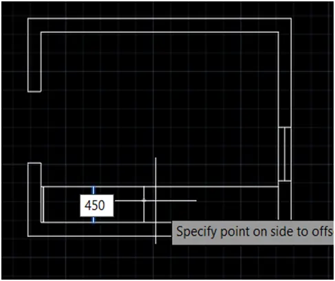
13.Offset 450mm
14.Offset 900mm
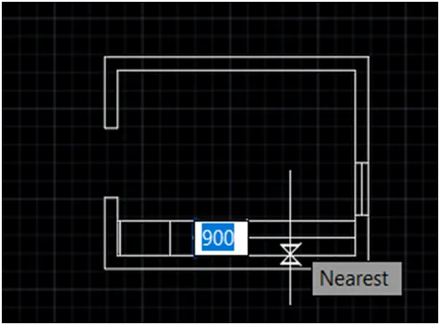
15.Again offset 450mm, 450mm, 450mm, 580mm, all the line go for the thickness of the drawers 20mm both side then trim the separate doors
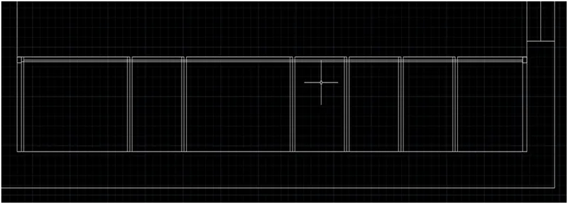
16.Then same create upper side of drawer the size is 1280mm, 900mm, 300mm, 450mm, 600mm, 685mm then create a components and place or insert the component Then create a surface for the hatch then hatch the surface then delete the surface then create a slider size is 800mm
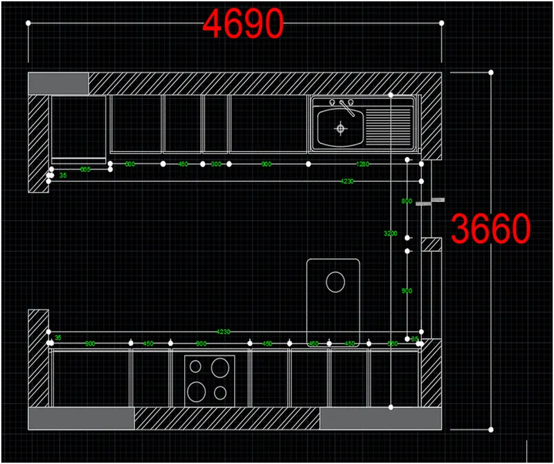
17.Then go for the dimension of the drawing and mention dimension in the drawing
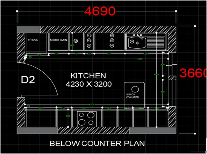
18.Then go for text command and give the detailing of the drawing
19.Copy the first drawing and delete the internal portion.
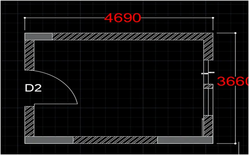
.20.Go for line and draw the overlap line and move the 350mm ang get offset 250mm
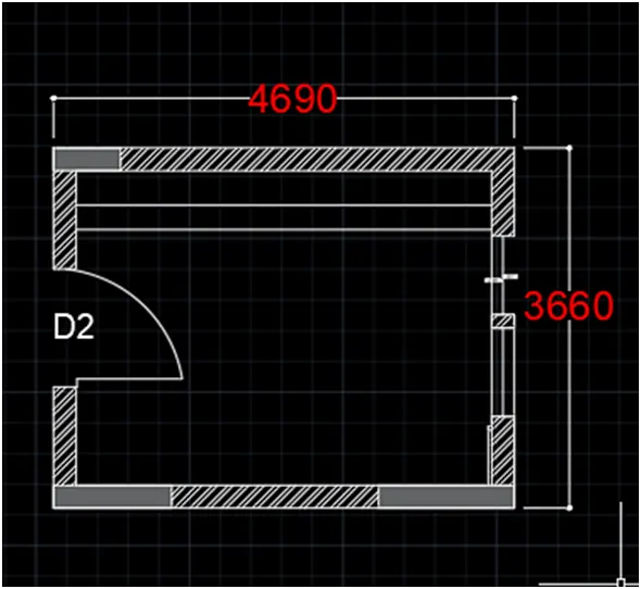
21.Go for the below 20mm offset on both line then create vertical line 350mm right side overlap and move the 35mm left side then 865mm, 865mm, 865mm, 600mm, 965mm then offset all line both side 20mm then join the above line Then trim the separation of the drawer
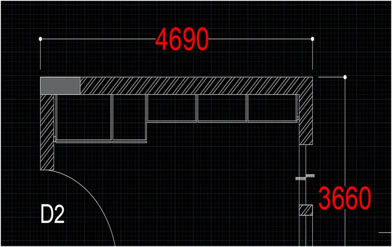
22.Then go for the below drawer Create a line 350mm overlap right side then move the 35mm left side then offset 1010mm, 900mm, 900mm, 900mm, 50mm then join the line and trim as shown in figure then create a box and draw diagonal line Then go for the text command and give the detail of the drawing then go for the dimension and mention the dimension of the drawing.
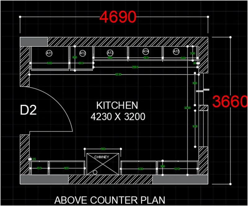
RESULT: The size of the kitchen is different as shown in figure the original size of the drawing is 4230 x 3200 mm.
COLUMN BAR SCHEDULE
AIM: To create a column bar schedule with their recommended size of bar and number of bars .
PROCEDURE:
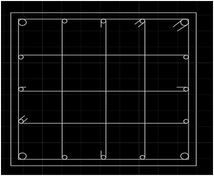
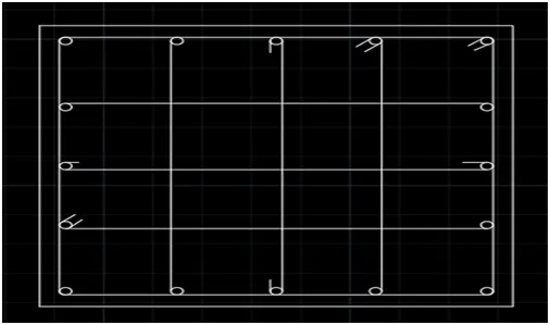
1.Open auto cad and set a unit engineering and draw a box 24” X 24”
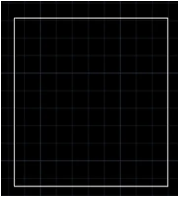
2.Go for offset 1” inner side
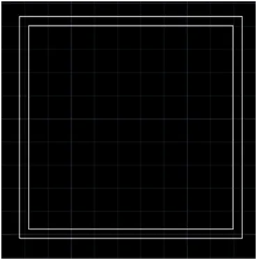
3.Then create a circle 1” and place a cornet then use of mirror place of all the corner
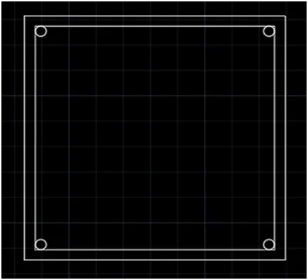
4.Then create a circle diameter is 0.62” and place all mid points and copy the object which distance is 6.65” both side
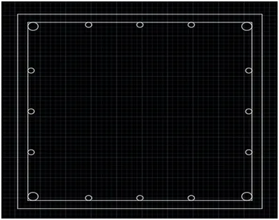
5.Then create a straight line to join the circle as shown in figure
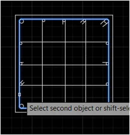
6.Then fillet the edges of the corner which radius is 0.5”
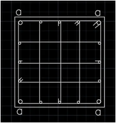
7.Create a text and insert the symbols
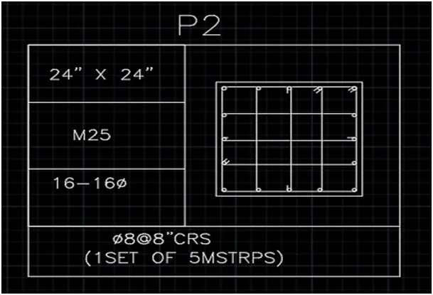
8.Then create a box and divide the box 5 parts as shown in figure then go for test command and give the details of the schedule as per details
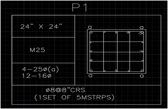
9.Create a same se P1 drawing and all bar size is 0.62” and the edges fillet is 0.3”
10.Then create a box and divide in 5 parts as shown in figure and give the details with the help of text command
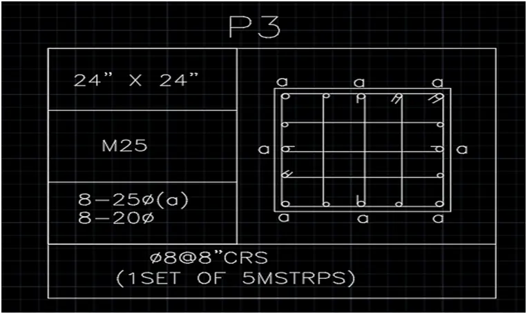
11.Create a same as P1 drawing and the bar size is 0.8” and 1” and the corner edge fillet is 0.5” Then give the details of the drawing with the help of text command
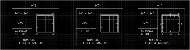
RESULT: Create a drawing with proper dimension and mention the details of the drawing as shown in figure.
RAFT FOOTING
AIM: To create a raft footing with all details and dimension and check the correction
PROCEDURE
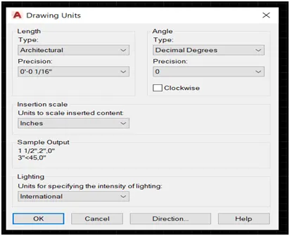
1.Open auto cad and set unit
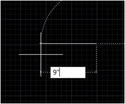
2.start for upper right to left create 9” horizontal line
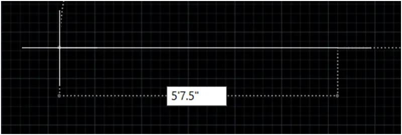
3.To continue the 5’7.5”
4.And continue the 4’6”, 4’, 7’, 2’, 5’9”

5.Then go for the downward side 5’7.5”, 3’7.5”, 4’9”, 5’10.5”, 5’7.5”, 3’9”, 5’9”, 13’10.5”, 9”
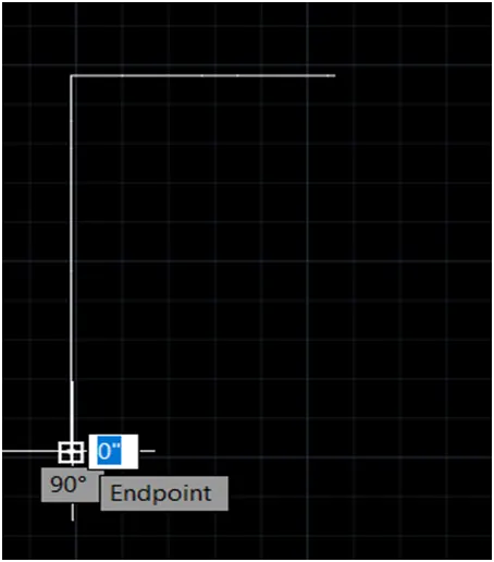
6.Then go for the left side 4.5”10’
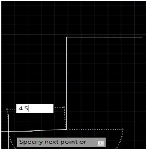
7.Then go for the right side 9” Then upward 7’ Then right side 29’3”
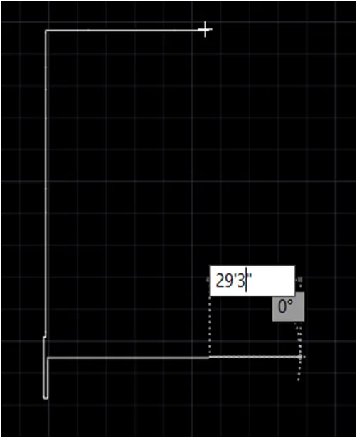
8.Then downward 7’ and close the box as shown in figure
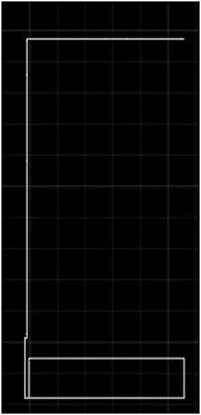
9.Then upward side are also close
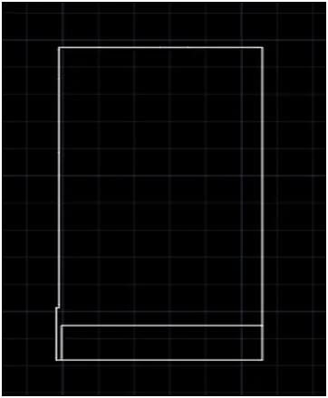
10.Then go for offset 9” as shown in figure
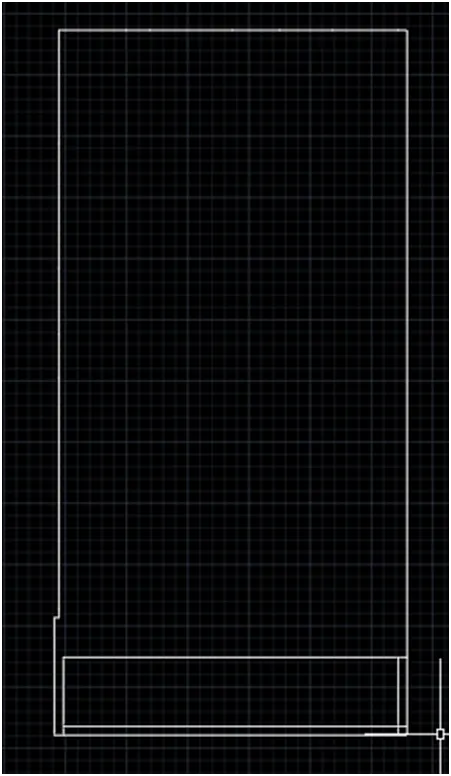
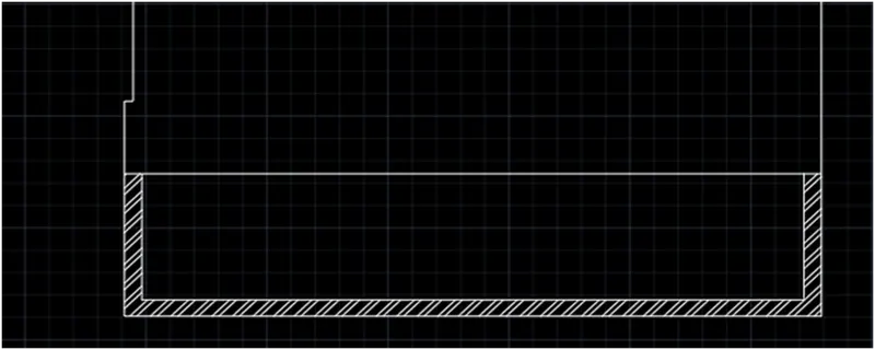
11.Then hatch the brick wall portion
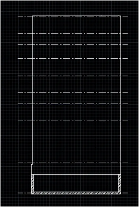
12.Then create a horizontally center line for midpoint of the brick wall then go for offset for the given distance or we go also end point of the each line to create a center line
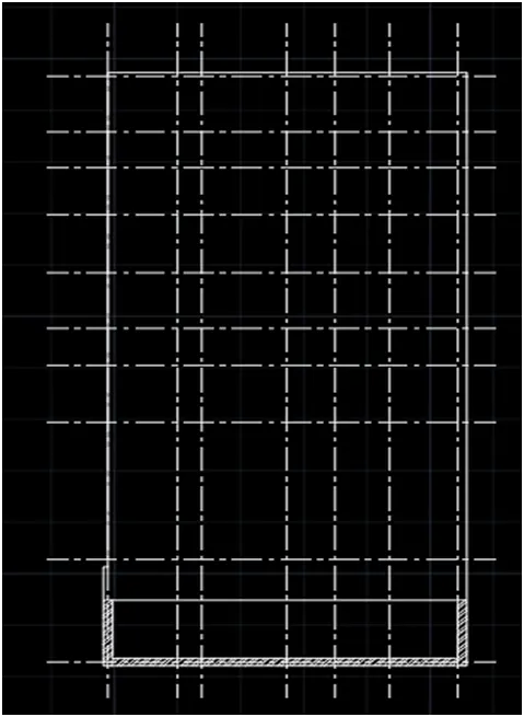
13.Then create a vertical center line as same as previous process
14.Then hatch the concrete portion
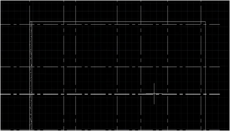
15.Then create a column size of bar the size is 24”x24”, 9”x24”, 24’x9”, 9”x18”, 18”x9”, 9”x28”, 24”x28” after creating then place the first 24”x24” size of column bars
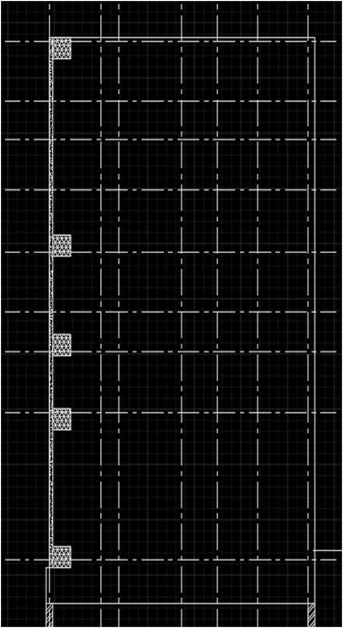
16.After 24’x24” size placing go to the next size 24”x9” as shown in figure
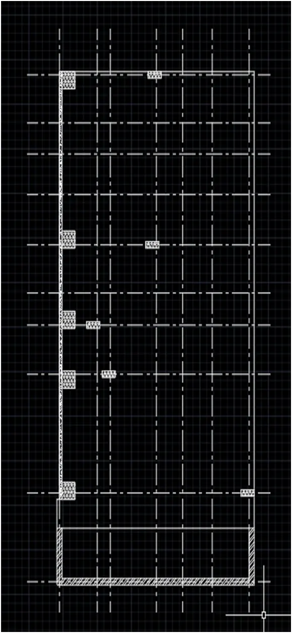
17.After 24’’x9” placing go for the 9”x24” size
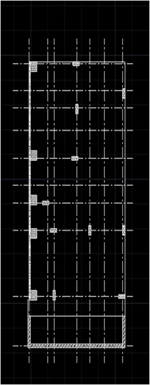
18.After 9”x24” placing go for the 18”x9”size then 9”x18” then 28”x9” and 9”x28”
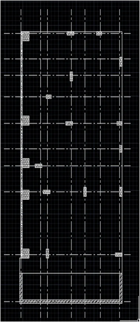
19.Then create a footing size of the columns
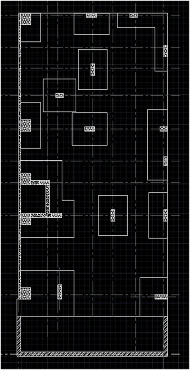
20. Then edit the main entrance of the plan After completing the drawing give the details of the drawing through the text command and mention the dimensions of the drawing.
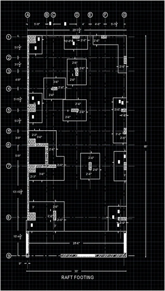
RESULT: The two column size is different as a given figure 9”x28” and 28”x9”