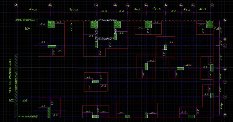
Creating a Wardrobe detailed drawing, Floor Plan, Kitchen Layout and Column Detail using AutoCad
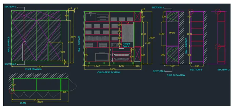
1. Draw the elevation and details of a wardrobe as shown in the Figure below. After sketching, you need to provide the dimensions and text with the use of layers. Use proper text styles and dimension methods to document it. Also, assume dimensions, wherever needed.
Note: All dimensions are in mm.
Aim-To draw the elevation anddetails of wardrobe using layers,dimension and text.
Procedure-
- In the command box type LINE press enter.
- specify first point and start drawing line of length 2800.
- make sure ortho mode is on and draw line f 2600.
- repeat line in -X direction and provide length 2800
- and then close.
- select offset command and provide offset distance of 12, and 488 in -Y direction.
- repeat offset and provide offset distance of 608.75 and 365 from sides.
- select linecommand and start drawing wall surface.
- using hatch command hatch the required area.
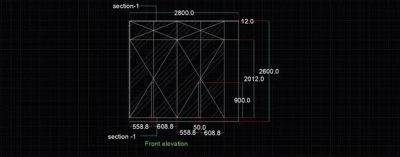
- in command box type rec and provide length as 2800 and width as 630.
- Draw outer wall surface using line command and provide dimensions.
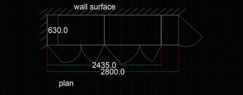
- In the command promt type Rec and specify length 2800 and width 2600.
- using offset command draw other members of cabinate.
- dimension the drawing.
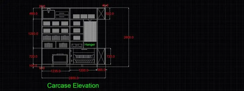
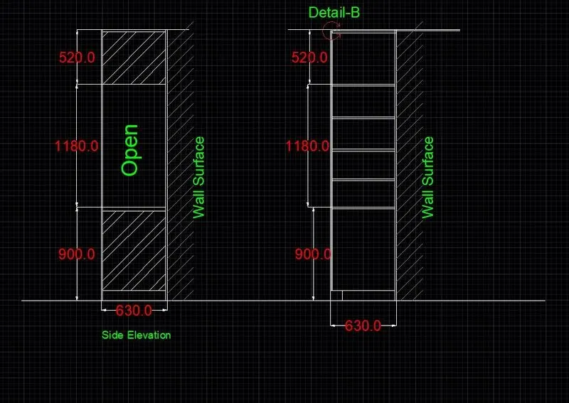
- to draw side elevation select ReC and provide length 630 and width 2600.
- select offset and provide offset distance 900,1180 and 520 in Y direction.
- draw other details using line and circle command.
- dimension the drawing.
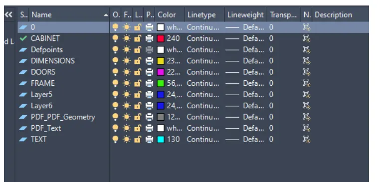
- select layer command create layer of all the elements in the drawing and put them in the respective layer.
Result- hence the details of wardrobe and elevation has been drawn.
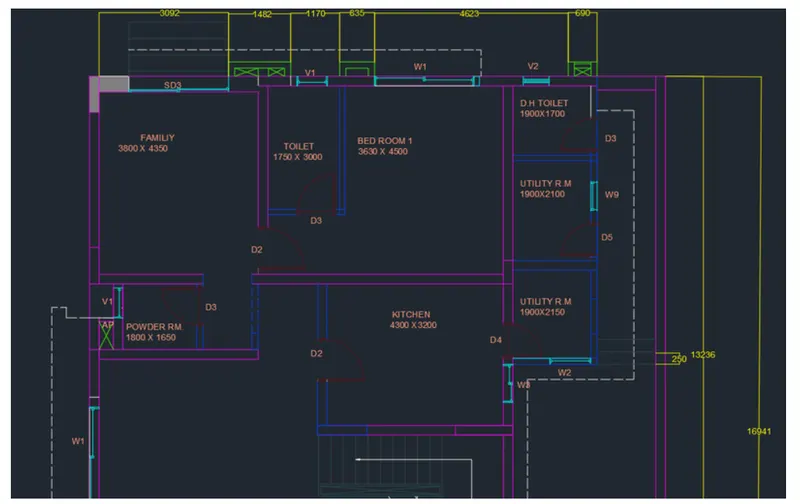
2. AIM-To draw floor plan using following details:
- Walls (Exterior and Interior)
Wall Thickness: Exterior Wall- 230mm, Interior Wall: 150 mm (Wherever Required)
- Doors and Windows: Assume the size of the doors and window.
2.1 Stairs: Tread-300mm, Riser-150mm
- Insert Text wherever required
- Insert the dimensions using proper dimension techniques
Procedure-
- In command prompt type L command and specify the base point .
- let's start sketching from family room of dimension 3800/4350.
- select offset command for outer wall of width300 mm.
- select offset command and provide offset distnace of 1750 for toilet.
- repeat offset and provide offset distance for bedroom 1 and utility room.
- keep providing offsets for door and windows.
- once the offset of all the objects is done as required in the drawing ,select trim command and trim all the unnecessary objects in the drawing.
- using hatch command hatch the outer wall by providing required hatch scale.
- For center marking and showingreferance lines select linetype from property and apply in the drawing.
- dimension the drawing .
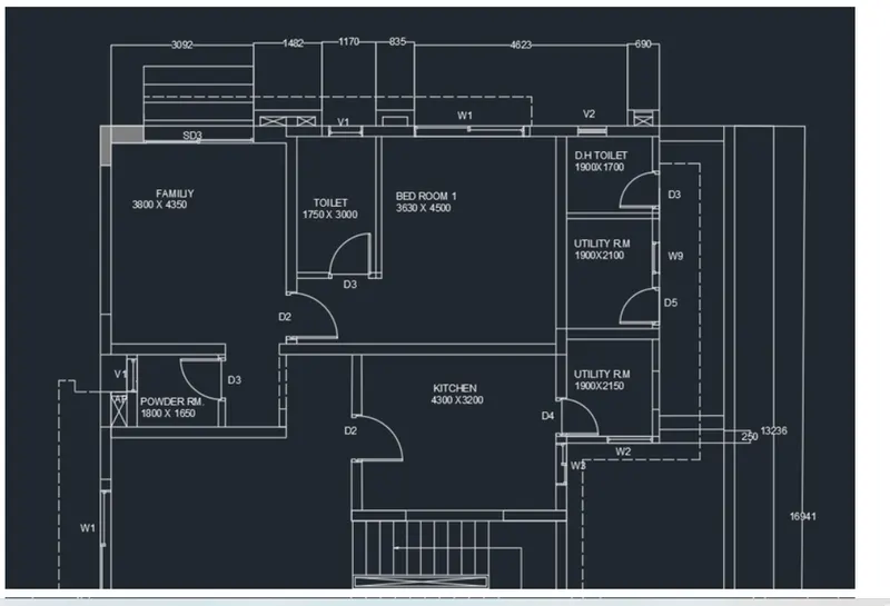
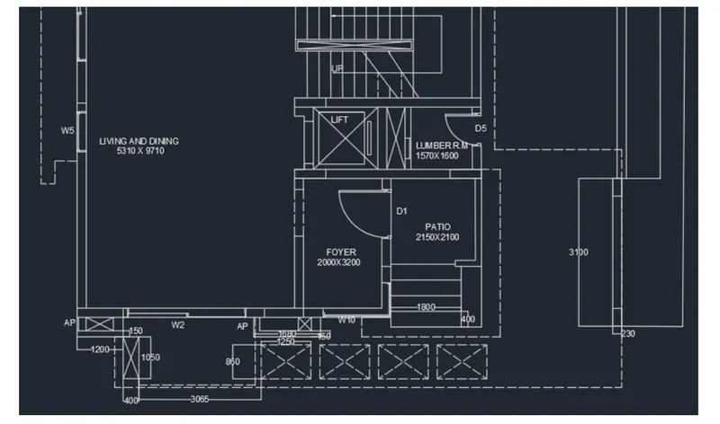
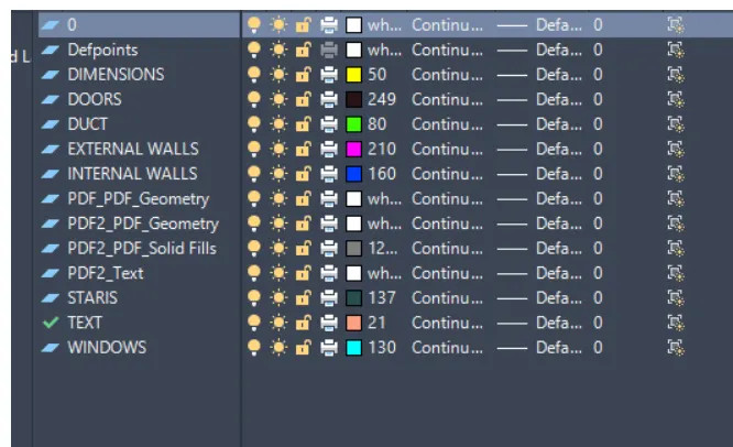
- once the drawing has been completed select layer command and put the objects of the drawing in their respective lay
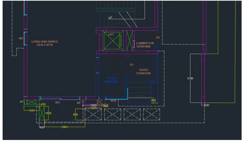
Result-
-
3. Creating kitchen layout.
Aim-To create kitchen layout.
Procedure-
- Set unit in mm.
- select REC command from ribbon tab and specify length and width as 4734/3688.
- selet offset command to offset it to a distance of 250mm.
- using arc and line command draw doors of the kitchen.
- using hatch command hatch the outer wall.
- using rectangle command draw fridge and micre ven.
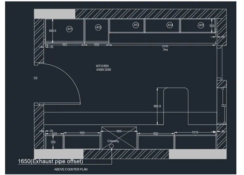
- select offset command and provide offset distance of 350,450,900,450,450 and 560 in horizontal direction.
- repeat offset command and provide offset distance of 600 in vertical direction.
- select dotted lines to draw snake counter.
- once the drawing has been done use trim command to trim the extras.
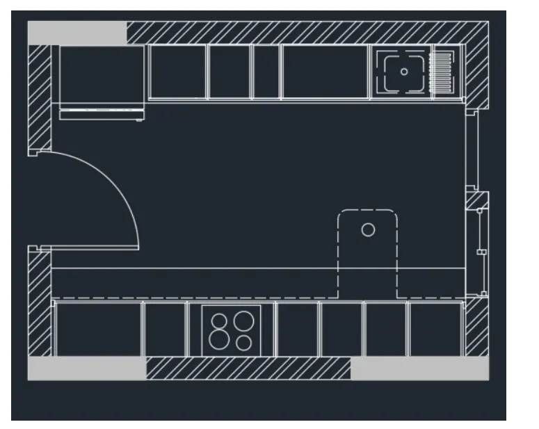
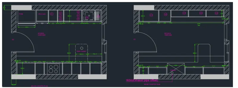
- Dimension the drawing and text whereever required in the drawing.
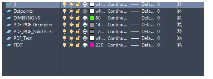
- after completion of drawing put the objects of the drawing in respective layer.
Result-
4.Aim- To sketch column details inserting text and dimension.
Procedure-
- select line command to create table.
- using text command text the table .
- use %%c to get diameter symbol in the drawing.
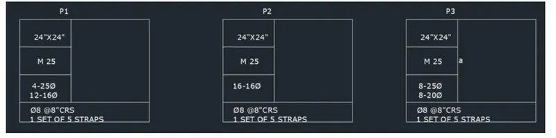
- use line command to draw column.
- select offset command to show cover distance between rebar and concrete.
- select circle and line command to show reinforcement details in the drawing.
- text drawing showing deatails of the column.
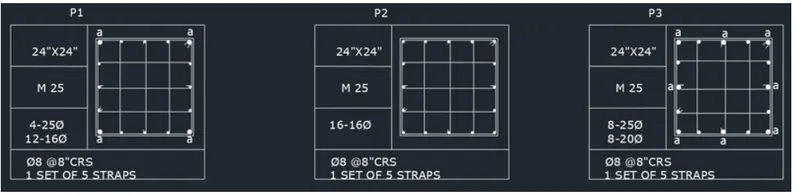
Result- column details and schedule has been drawn.
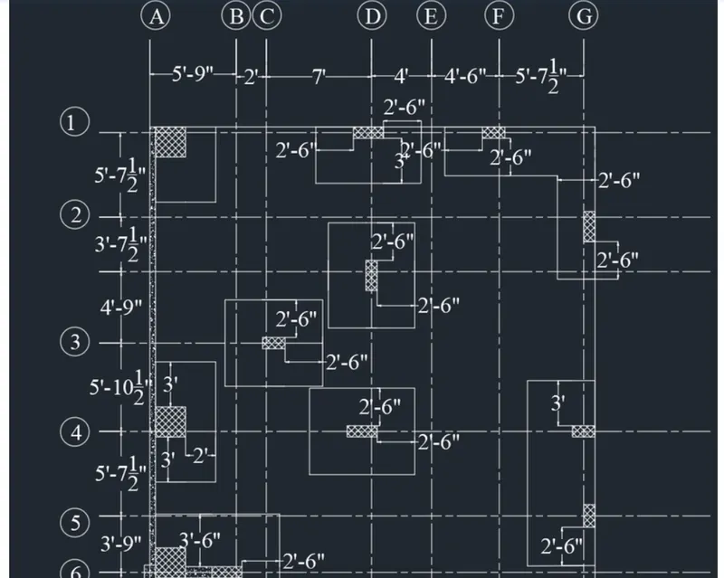
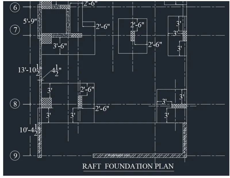
5. Aim- To draw raft layout, column and grid lines.
Procedure-
- select unit and set it to engineering.
- to draw grid line select linetype and load long dash .
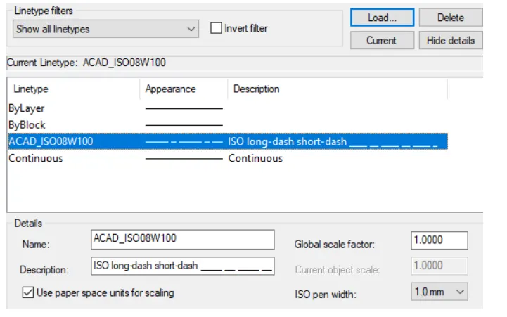
- draw grid line A and 1.
- select offset command and provide required offset distance to raw grid B,C,D,E,F and g.
- repeat offset command and provide offset dstance to draw 2,3,4,5,5',6,7,8 and 9.
- once the grid line have been drawn select continuous line type and draw footing and column using offset and hatch command.
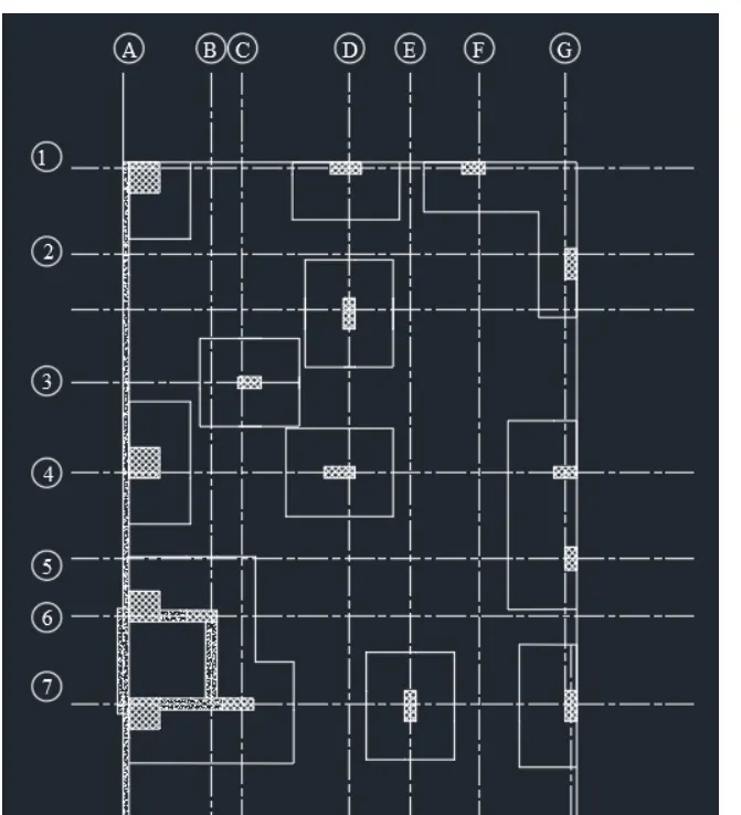
- after completion of sketching grid,footing and column, provide dimension to the drawing and text grid lines.
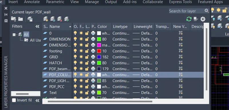
- once all the editing have been done using trim ,dim, and text command lets use layer command and put the grouped objects of the drawing in their respective layer.
Result-