Creating a Wardrobe detailed drawing, Floor Plan, Kitchen Layout and Column Detail using AutoCad
Drawing 1:
Aim: To draw the elevation as well as details of a wardrobe as shown in the figure and to provide the dimensions and text with the help of layers.
Commands Used:
- Line command
- Xline
- Offset
- Layers
- DText
- Rectangle
- Copy
- Circle
Procedure:
Step 1:
- The Drawing Units properties dialog box is used to set the units type as a decimal and the insertion scale is set as Millimeters with a precision as 0.00
- The limits command is used to set the limits.
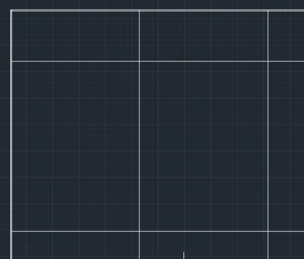
- The Xline command is used to draw the vertical and horizontal lines according to the dimensions given in the figure and the front elevation of the wardrobe is created.
- The offset command is used to offset the thickness of the wardrobe by 12 mm on the top and right sides.
Step 2:
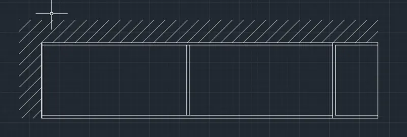
- The Xline command is used to draw the vertical and horizontal lines according to the dimensions given in the figure and the Plan of the wardrobe is created.
- The offset command is used to offset the thickness of the wardrobe by 12 mm in the required lengths.
- The hatch command is used to mark the wall surface around the wardrobe.
Step 3:
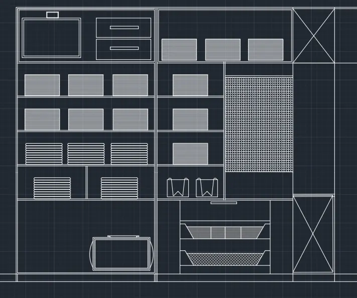
- Using the extension of the Xline drawn over the total horizontal length is used as a reference to draw the carcase elevation.
- In the carcase elevation, several pieces of furniture are to be created which were mostly created using the commands such as Line, Arc, Copyàarray, Rectangle, Trim, and Hatch.
Step 4:
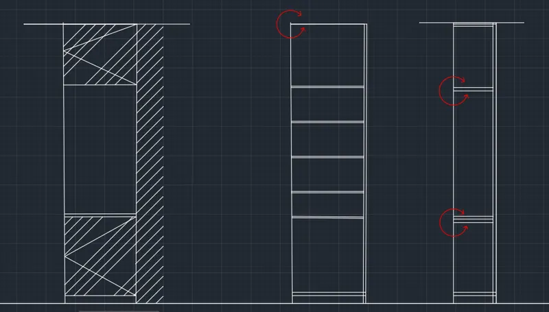
- To draw the side elevation the Line tool is predominantly used.
- The hatch command is used to mark the Wall surface.
- Next, Section 1 and Section 2 are drawn using the Line command and offset command.
Step 5:
- The dimensions command is used to mark all the dimensions accordingly.
- The Dtext command is used to enter the texts into the drawing.
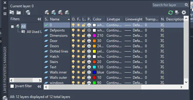
- The Layer properties command from the ribbon is used for several additional layers and different colors are given for each layer.
- The dimensions and texts are placed in two different layers: the racks, doors, and cabinet frame. Every element is placed in different layers and given a contrasting color that goes with the dark theme.
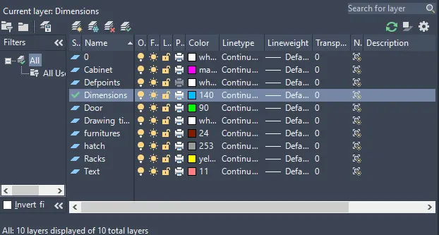
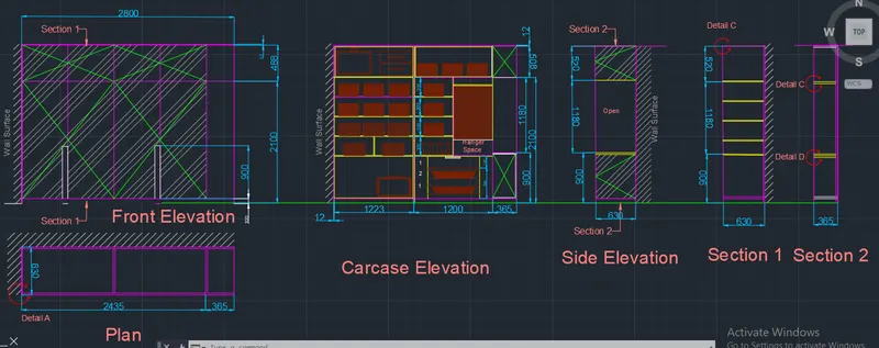
Result: The elevation, as well as details of a wardrobe in the given figure, are drafted by providing the dimensions and text with the use of layers.
Drawing 2:
Aim: To draw the floor plan according to the given figure.
Commands Used:
- Line command
- Hatch
- Trim
- Xline
- Offset
- Layers
- DText
- Rectangle
- Copy
- Circle
Procedure:
Step 1:
- The Drawing Units properties dialog box is used to set the units type as a decimal and the insertion scale is set as Millimeters with the precision as 0.00
- The limits command is used to set the limits.
- The XLine command is used to draw vertical and horizontal lines.
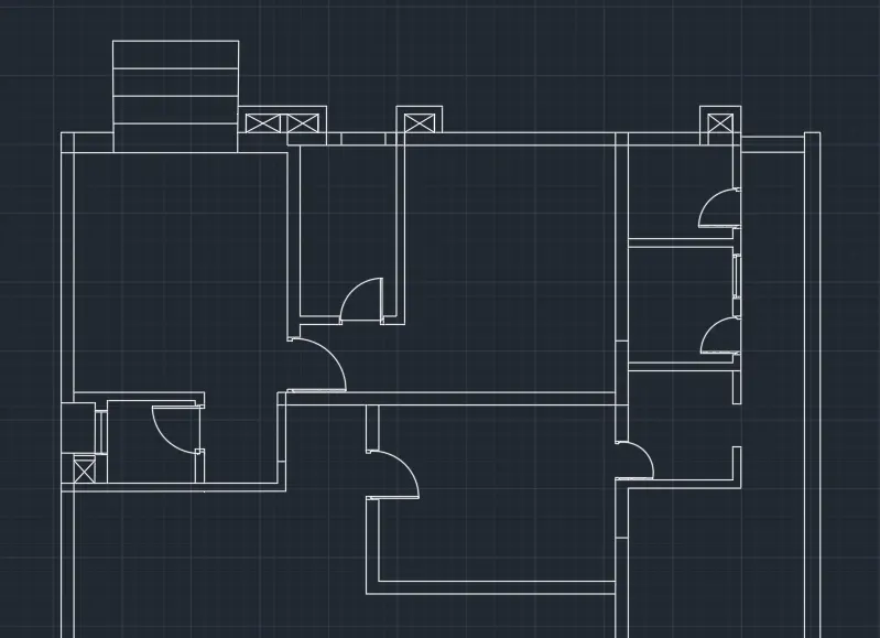
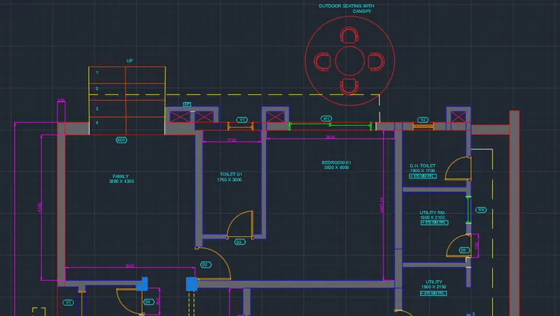
- The outer wall is of thickness 230mm and the inner wall is of thickness 150mm.
- The family room of dimensions 3880*4350mm, Toilet - 1750*3000mm, Bedroom – 3830*4500mm, D.H toilet – 1900*1700, Utility room – 1900*2100 and Kitchen – 4300*3200 are drafted using XLine command, and the trim commands.
Step 2:
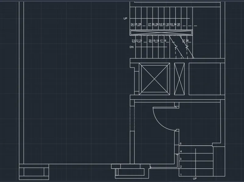
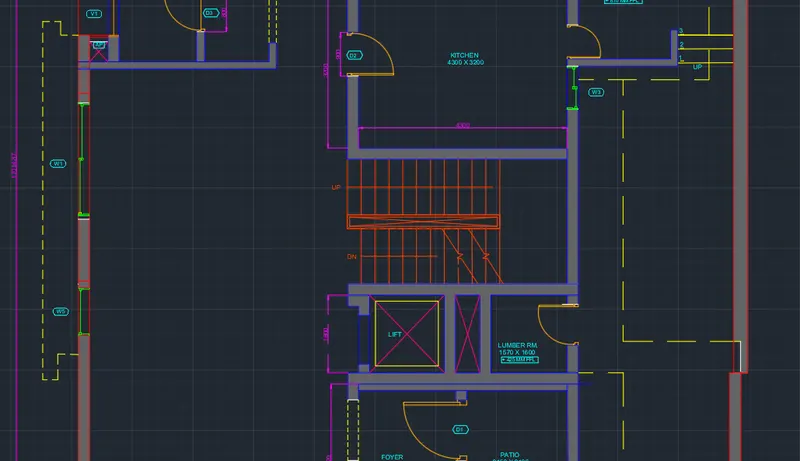
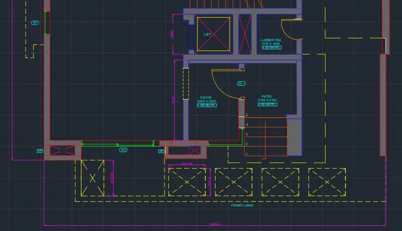
- The stairs are drawn using the Line, copyàArray method to draw all the threads.
- The lift room and the lumber room are further drafted using the Xline and trim method.
- The rooms of dimensions respectively Foyer- 2000*3220, Patio- 2150*2100, Lumber room – 1570*1600
Step 3:
- The doors and windows are dimensioned respectively as given:
Doors Windows: Ventilators:
D1 - 1000*2100mm W1 - 2700*1500 mm 1. V1- 800*500 mm
D2 - 900*2100mm W2 - 2500*1500 mm 2. V2- 750*500 mm
D3 - 800*2100mm W3 - 900*1500 mm
D4 - 750*2100mm W5 - 1000*1500 mm
D5 - 700*2100mm W9 - 800*1500 mm
SD - 2256*2100mm
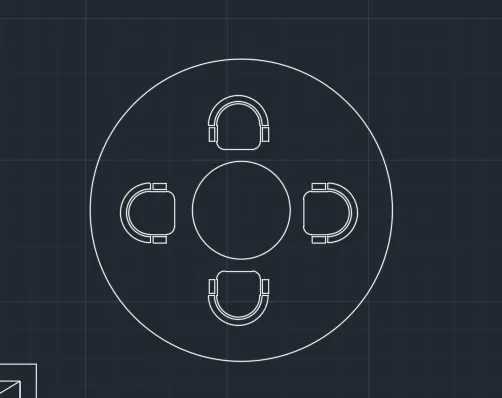
- Firstly, draw two circles, first of radius 500 mm and second of radius 1000mm
- Use the rectangle, line, and arc commands to create the chair.
- Draw a circle as such the radius is the length from the center of the circle to the geometric center of the chair.
- Use the Array command and path curve option to replicate the chairs in the four directions.
- Enter the number of items as 4 and enter the value for between as the value of the ¼th of the last drawn circle.
- Mark the radial dimensions of the two circles.
- Scale the Canopy accordingly.
Step 4:
- The dimension command is used to mark the dimensions of the various rooms in the plan.
- The DText command is used to enter the single line and multiline texts in the plan and the rooms are marked accordingly.
- The layer properties toolbar is used to create new layers and assign the desired colors to each layer.
- The elements to be added are selected and the respective layer is selected from the layer ribbon to add those elements into the layer and the color of the elements automatically changes.
Result: The given floor plan is drafted using AutoCAD 2021.
Drawing 3:
Aim: To draw the kitchen layout as shown in the figure.
Commands Used:
- Line command
- Hatch
- Trim
- Xline
- Offset
- DText
- Rectangle
- Copy
- Circle
Procedure:
Step 1:
- The Drawing Units properties dialog box is used to set the units type as a decimal and the insertion scale is set as Millimeters with a precision as 0.00
- The limits command is used to set the limits.
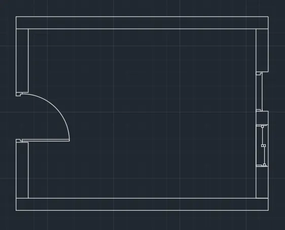
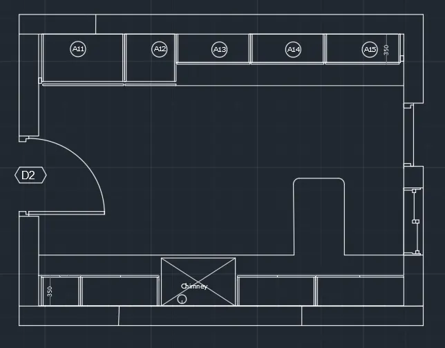
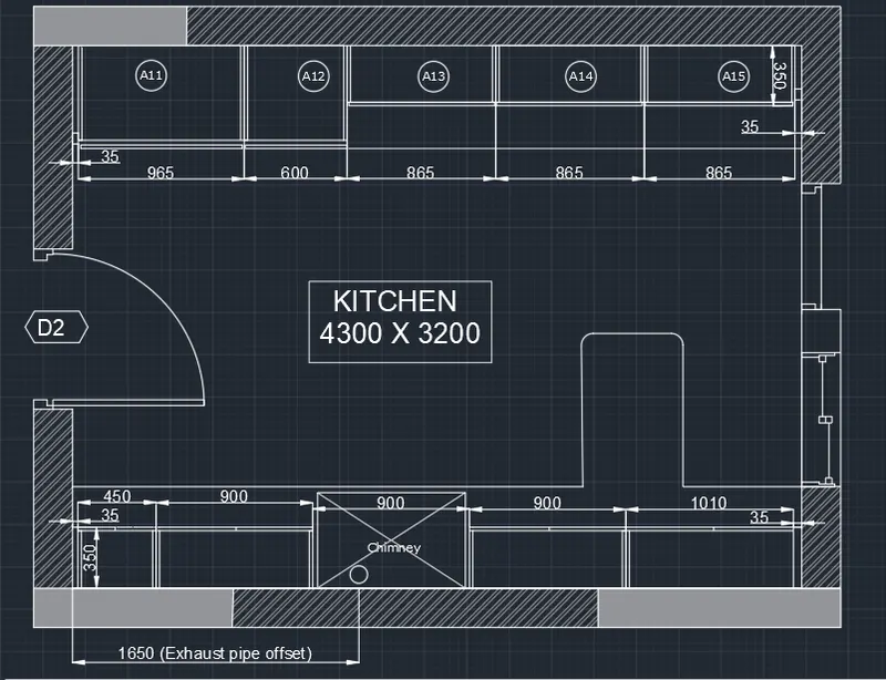
- The rectangle command is used to draw a rectangle of dimensions- 4300*3200 mm
- The door of dimension 900*2100 mm is created in the wall layout of the kitchen plan.
- The windows and the ventilator opening are marked in the plan.
Step 2:
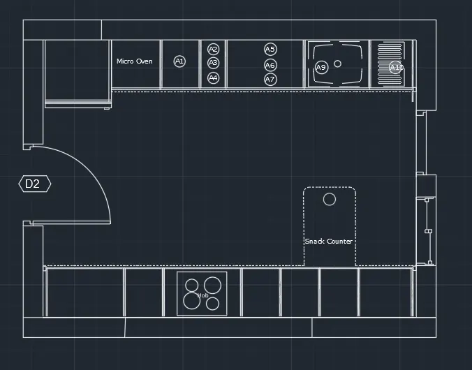
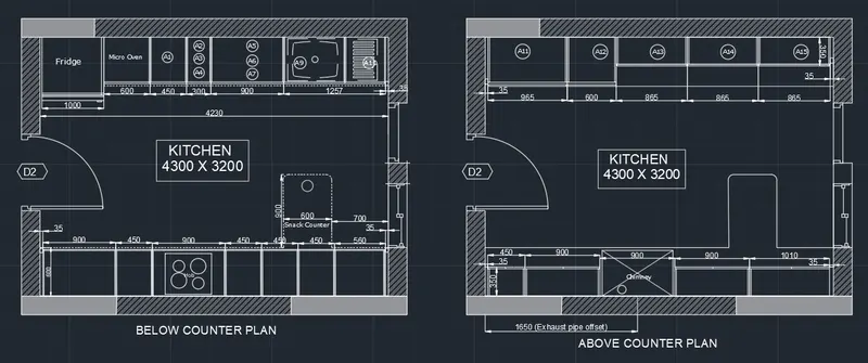
- The line and the rectangle command are used to draw the counters, chimney and the elements of the kitchen on one side.
- The snack counter is marked by a dotted line since this is a below counter plan.
- On the other side the Fridge, micro-oven, and the sink are drawn with the help of line and rectangle command using the given dimensions for reference.
Step 3:
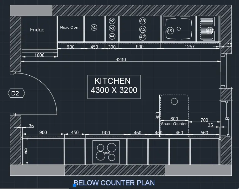
- The hatch command is used to give different hatch layouts in the wall plan of the kitchen.
- This plan as a whole is copied and moved to the side, which will be used to draw the above counter plan.
- In the below counter plan the Dtext command is used to write the texts and the dimensions command is used to mark the dimensions of the plan.
Step 4:
- In the copied Layout the unwanted counters are all trimmed out using the trim command.
- The line type of the dotted line for the snack counter is changed to a straight line using the “by layer” option in the ribbon.
- The chimney and all the other counters are drawn according to the given dimensions.
- The hatch command is used to give different hatch layouts in the wall plan of the kitchen.
- The DText command is used to write the texts and the dimensions command is used to mark the dimensions of the plan.
- The two drawings are marked as Below counter plan and Above counter plan respectively.
Result: The given Kitchen plan is drafted using AutoCAD 2021.
Drawing 4:
Aim: To sketch the column details as shown in the figure.
Commands Used:
- Line command
- DText
- Rectangle
- Copy
- Circle
Procedure:
Step 1:
- The Drawing Units properties dialog box is used to set the units type as engineering and the insertion scale is set as Feet with the precision as 0’-00”
- The limits command is used to set the limits.
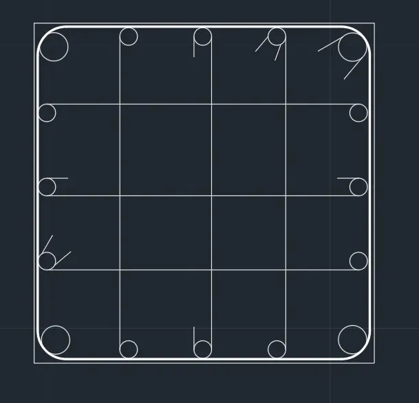
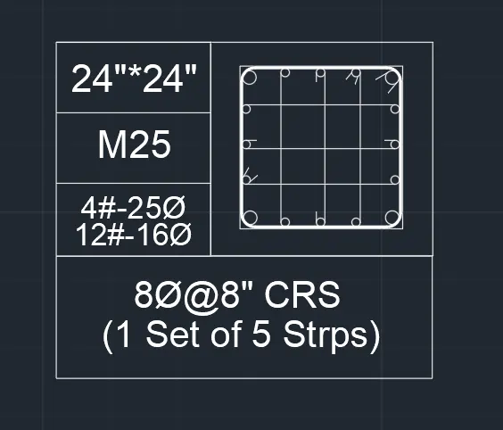
- A rectangle of dimensions 24”*24” is drawn using the rectangle command.
- The rectangle is offseted by 1” and the corners are filleted with an radius of 3”.
- The radius of the rods are given as the following:
- 8mm diameter- 0.31”
- 16mm diameter- 0.62”
- 25mm diameter- 1”
- Using these dimensions as reference the circle command is used to draw the rods and the circle are positioned accordingly.
- The copy command is used to move and place the repeated rods.
- The nearest and quadrant options are selected from the object snap drop down box.
- The stirrups are now drawn and marked.
Step 2:
- The line and rectangle commands are used to draw the sections in which the texts are to be written.
- The Dtext command is used to write the texts accordingly with respect to the given figure.
Step 3:
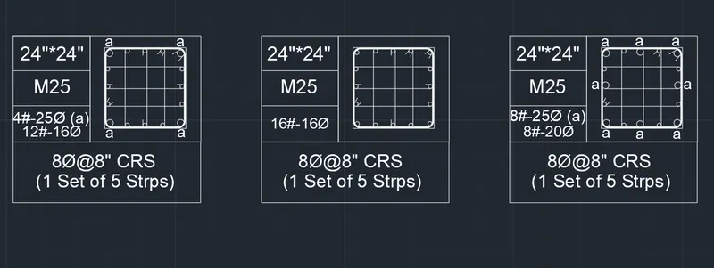
- This is drawing is then copied using the copy command, a reference point is chosen and the array is given as 3 numbers. The drawing are positioned accordingly
- Now the texts of each drawing is changed by double clicking the texts to be changed and the new values are entered.
- The circular dimensions of the rods are changed by clicking the grip in the quadrant of the circle and the new value Is given to change the dia of the circle.
Result: The given column details schedule is drafted using AutoCAD 2021.
Drawing 5:
Aim: To sketch the Raft Layout as shown in the figure.
Commands Used:
- Line command
- Xline
- Hatch
- Dimensions
- DText
- Rectangle
- Copy
- Circle
Procedure:
Step 1:
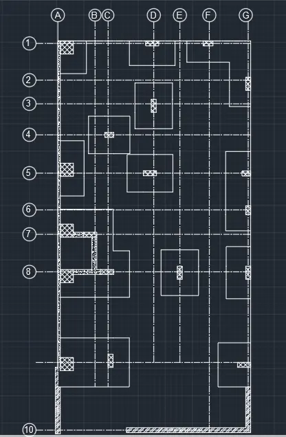
- The Drawing Units properties dialog box is used to set the units type as Architectural and the insertion scale is set as Feet with the precision of 0’-00 ½”
- The limits command is used to set the limits.
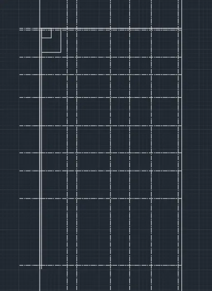
- The Xline command is used o draw a horizontal and vertical line.
- The line type is changed to ACAD_ISO08W100 and the Xline command is used to draw horizontal and vertical reference lines which are used to mark the raft positions.
- The excess lines are cropped out using the Trim command.
- The XLine are spaced out correctly using the dimensions in the given figure as reference.
Step 2:
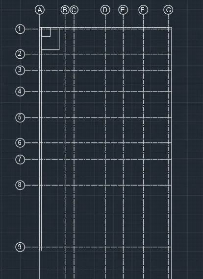
- The circle command is used to draw a circle as such the bottom of the circle touches the top of the reference line. The Dtext command is used to enter the value of the reference line in this case “A”.
- This circle along with the text is selected and copied using the copy command. This is then moved and positioned correctly to mark each of the reference lines.
- The text inside is double-clicked to change the text for each reference line.
Step 3:
- The rectangle command is used to draw the rafts in the raft plan.
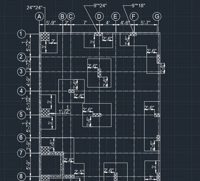
- The different sizes of the columns are of the following
- 24”*24”
- 9”*24”
- 9”*16”
- Once each type of a rectangle is drawn it can be then copied and moved to other parts of the plan where a similar column type is used to save time.
- The raft around the column is drawn with the help of dynamic mode and poly line command.
- The spacing between the raft and the column is to be marked correctly by referring the given plan.
- The hatch command is used to given different hatches to mark the column and the concrete column connector.
- The different Hatches used are ANS 132 and AR-Conc.
Step 4:
- The dimensions command is used to mark all the dimensions of the raft plan.
- The leader command is used to Enter the dimension details of each type of the column.
- The unwanted reference lines at the base of the plan is trimmed out using the Trim command.
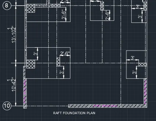
Result: The given Raft layout is drafted using AutoCAD 2021.