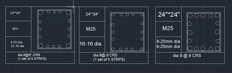
Creating a Wardrobe detailed drawing, Floor Plan, Kitchen Layout and Column Detail using AutoCad
1.)
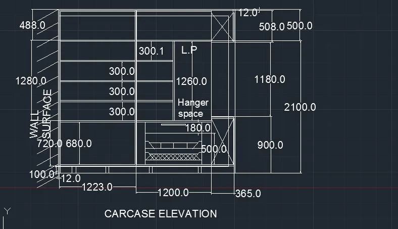
AIM:To draw the elevation and details of the wardrobe using AUTO-CAD.
PROCEDURE:
STEP 1:
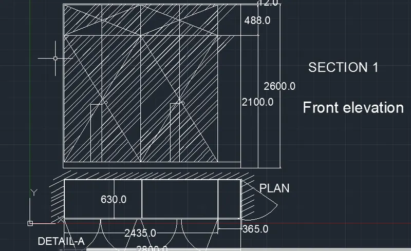
- Select the "Line" command from the ribbon tab and draw the line of 2100 mm in vertical positive direction.
- Select "Line" in the command prompt and draw another vertical line of 488mm in vertical positive direction.
- Select "Line" from the ribbon tab and draw the vertical line of 12mm in vertical direction.
STEP 2:
- Select "Line" from the ribbon tab and draw horizontal line of 2435mm in left direction.
- Draw another line of 365 mm in the horizontal left direction.
- Enter line in the command prompt and draw the line of 2600 mm in downward direction.
- Enter "close" in order to draw the rectangle.
- Type " offset" in the command prompt and draw a line of 2100mm by selecting the base line.
- Type "offset" in the command prompt and draw a line of 488mm by selecting the previous line.
- Type "offset" in the command prompt and and enter the distance 12mm thus draw the line.
STEP 3:
- Select "Line" from the ribbon tab and enter distance of 2435mm in horizontal positive direction.
- Enter "Line" and draw a vertical line of 630 mm in vertical positive direction.
- Select "Line" from the ribbon tab and enter distance of 2435mm in horizontal left direction.
- Enter "Line" and draw a vertical line of 630 mm in vertical downward direction.
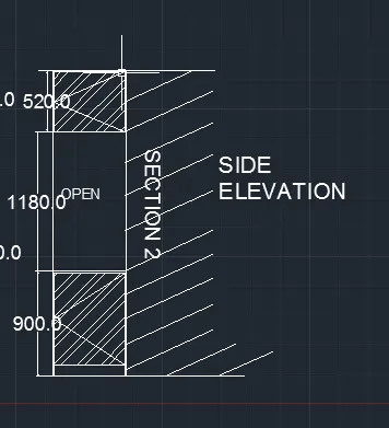
- Enter "offset" of the vertical line in the right thus drawing a line at a distance of 365mm in right direction.
- Draw a line of 630 mm in vertical positive direction.
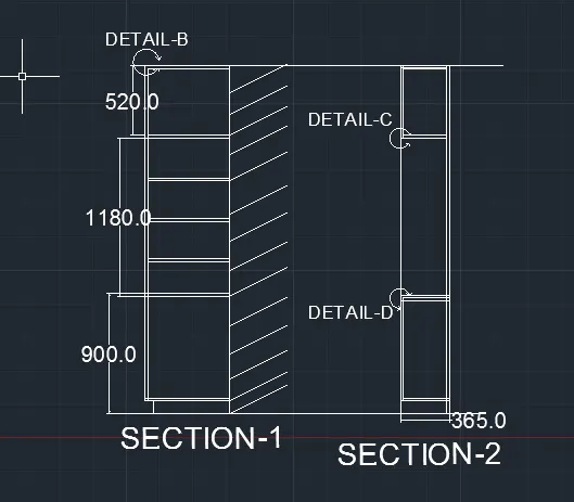
- Select " dimensions" from the ribbon tab and select the end points thus entering the dimensions of the particular line.
STEP 4:
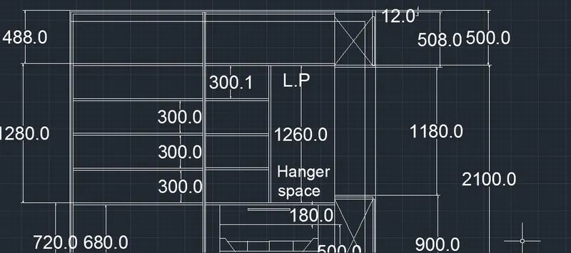
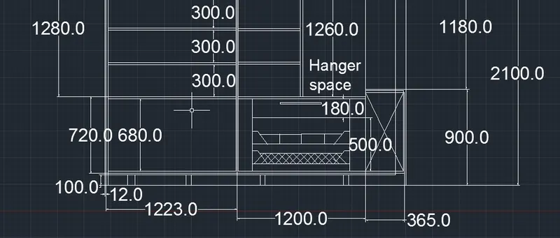
- Draw the wardrobe by selecting "Line " from the ribbon tab.
- Enter the distance as
STEP 5:
STEP 6:
STEP 7:
2.)
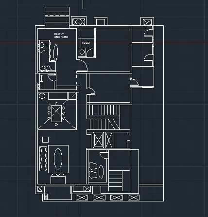
AIM:To draw the floor plan using AUTO-CAD.
PROCEDURE:
STEP 1:
- Select line command from the command prompt and draw a line in horizontal x-direction of 5310 mm.
- Draw the line in the vertical y-direction of 9710mm.
- Draw a line of 1800mm in horizontal x-direction.
- Select the line and draw an offset of the same in vertical direction of 230mm.
- Draw a line of 1650mm in the vertical y-direction.
- Select the line and draw an offset of the same in vertical direction of 230mm.
- Draw a line in vertical y-direction of 4350mm and then draw the offset of the same in the upward vertical direction of 300mm.
- Draw a line in horizontal x-direction of 3880mm dimension.
- Draw a line in horizontal x-direction of 230 mm.
- Draw a line in horizontal x-direction of 1750mm and then extend it adding 3830mm and extend it further with the dimension of 1900mm.
- Draw a line in vertical negative y-direction of length 1700mm and extending the line by adding the dimensions of 2100,2150 1600,2000,1600,3220mm.
- Draw a line in negative x-direction and type "CLOSE" in the command prompt.

STEP 2:
- Draw the staircase with the tread of 300mm and riser of 150mm.
- Draw the boundary of the same floor plan.
STEP 3:
- Draw the doors and other aesthetics as required according to the diagram.
- Using text from the panel and enter the texts.
- Thus the floor plan is drawn using the command.
3.
AIM: To draw the kitchen layout using AUTO-CAD.
PROCEDURE:
STEP 1:
- Select "Line" command from the ribbon tab and draw a horizontal line of 4300 mm in positive right direction.
- Draw the same line in the vertical direction of length 3200 mm in positive y-direction.
- Draw the line in horizontal left direction of length 4300 mm.
- Enter "close" thus closing the whole section.
- Select the horizontal line below and enter "offset".
- Enter the dimension as 600mm in vertical direction.
STEP 2:
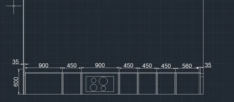
- Draw a line of 35 mm in right vertical direction.
- Enter "offset' and enter the distance as 900 mm in right horizontal direction.
- Enter the "offset" command and enter the distance as 450 mm in horizontal direction.
- Enter the "offset" and enter the distance as 900 mm in horizontal direction.
- Enter the "offset" command and enter the distance as 450 mm in horizontal direction.
- Enter the "offset" and enter the distance as 450 mm in horizontal direction.
- Enter the "offset" command and enter the distance as 450 mm in horizontal direction.
- Enter the "offset" and enter the distance as 560 mm in horizontal direction.
- Enter the "offset" command and enter the distance as 35mm in horizontal direction.
STEP 3:
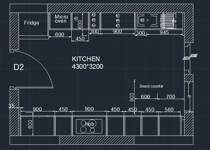
- Draw a line of 35 mm in right horizontal direction.
- Enter "offset' and enter the distance as 1000 mm in right horizontal direction.
- Enter the "offset" command and enter the distance as 600mm in horizontal direction.
- Enter the "offset" and enter the distance as 450 mm in horizontal direction.
- Enter the "offset" command and enter the distance as 300 mm in horizontal direction.
- Enter the "offset" and enter the distance as 900 mm in horizontal direction.
- Enter the "offset" command and enter the distance as 300 mm and 945mm in horizontal direction.
- Enter the "offset" and enter the distance as 560 mm in horizontal direction.
- Enter the "offset" command and enter the distance as 35mm in horizontal direction.
STEP 4:
- Select the line and enter "offset" of 230 mm in the outer side of the line.
- Repeat it in all the four sides.
- Enter "Hatch" and select the required points thus select the "WALL" hatch and press enter.
- Draw a circle of any dimension and place it in the places where it is used in the layout.
- Select "text" from the ribbon.
- Select "single line text" and enter the height as "100" and angle of rotation as "0'".
- Enter the text required in different sections.
- Select "Dimensions" from the ribbon tab and enter the required dimensions.
STEP 5:
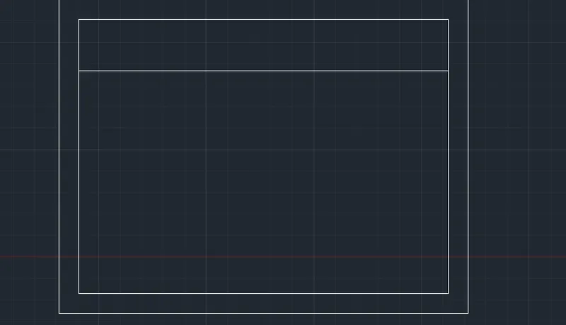
- Select "LINE" command from the ribbon tab.
- Enter the dimension as 4300 mm in horizontal right direction.
- Enter the dimension as 3200 mm in vertical positive direction.
- Repeat the same in opposite directions.
- Select the line and enter "OFFSET" of 230 mm in all the four sides.
- Select the line and enter "offset" of 600 mm from inner wall and press enter.
STEP 6:
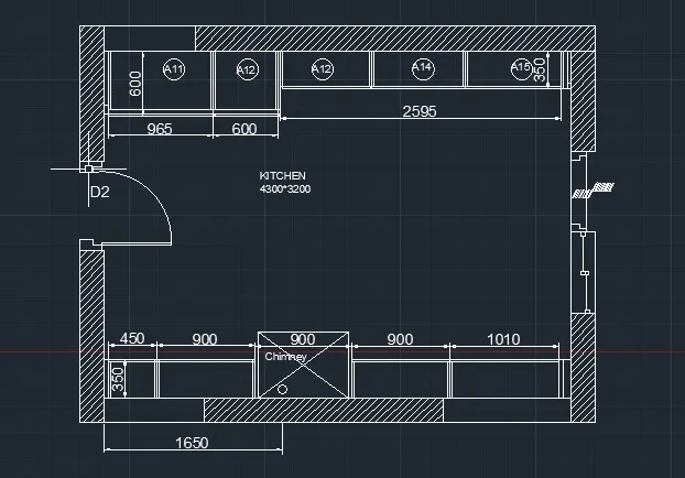
- Draw a line of 35 mm in right horizontal direction.
- Enter "offset' and enter the distance as 450 mm in right horizontal direction.
- Enter the "offset" command and enter the distance as 900mm in horizontal direction.
- Enter the "offset" and enter the distance as 900 mm in horizontal direction.
- Enter the "offset" command and enter the distance as 900 mm in horizontal direction.
- Enter the "offset" and enter the distance as 1010 mm in horizontal direction.
- Enter the "offset" command and enter the distance as 35 mm in horizontal direction.
STEP 7:
- Draw a line of 35 mm in right horizontal direction.
- Enter "offset' and enter the distance as 965 mm in right horizontal direction.
- Enter the "offset" command and enter the distance as 600mm in horizontal direction.
- Enter the "offset" and enter the distance as 865 mm in horizontal direction three times.
- Enter the "offset" command and enter the distance as 350 mm in vertical negative y-direction.
- Enter the "offset" command and enter the distance as 35 mm in horizontal direction.
STEP 8:
- Select the line and enter "offset" of 230 mm in the outer side of the line.
- Repeat it in all the four sides.
- Enter "Hatch" and select the required points thus select the "WALL" hatch and press enter.
- Draw a circle of any dimension and place it in the places where it is used in the layout.
- Select "text" from the ribbon.
- Select "single line text" and enter the height as "100" and angle of rotation as "0'".
- Enter the text required in different sections.
- Select "Dimensions" from the ribbon tab and enter the required dimensions.
4)
AIM:TO DRAW A COLUMN DETAIL USING AUTO-CAD.
PROCEDURE:
STEP 1:
- Select rectangle from the panel and draw a rectangle using that by moving the cursor.
- Select line command from the command prompt and draw line thereby seperating the sections.
- Select text from the panel and thus enter the dimension and the type of reinforcement used in the schedule given.
- Select Circle command to draw the reinforcements shown in the figure.