Creating a Wardrobe detailed drawing, Floor Plan, Kitchen Layout and Column Detail using AutoCad
CREATING A WARDROBE DETAILED DRAWING, FLOOR PLAN, KITCHEN LAYOUT AND COLUMN DETAIL USING AUTOCAD
Introduction:
AutoCAD's dimensioning tools can automatically measure distances and place dimensions on your drawing. You have to just select the objects, appropriate dimensions will be added by the AutoCAD.
Dimension tools can be acccessed from the Dimensions panel on the Annotate tab of the ribbon.
AutoCAD divides dimension into four main categories: Linear, Radial, Ordinate and Angular. Always use object snap option to pick dimension line origin.
There are different dimension line commands:
1. Linear Dimension commands:
- It is used to dimension along straight lines.
- There are five linear dimension commands: DIMLINEAR, DIMCONTINUE, DIMBASELINE, DIMALIGNED and DIMROTATED.
- DIMLINEAR is the most commonly used command.
- DIMLINEAR - This command is used to generate horizontal and vertical line.
- DIMCONTINUE - This command is used to add a string of dimensions quickly that align perfectly.
- DIMBASELINE - This command is used to generate a series of dimensions from a single basepoint.
- DIMALIGNED - This command is used to generate aligned dimensions. These are dimensions along inclined lines which cannot be dimensioned using DIMLINEAR command.
- DIMCONTINUE and DIMBASELINE can be used in conjuction with DIMALIGNED dimensions.
2. Radial dimension commands:
There are two main radial dimension commands, DIMDIAMETER and DIMRADIUS. Both commands result in a similar looking dimensions so AutoCAD automatically inserts "R" to indicate a radius and the dimension symbol to indicate a dimension.
- Diameter dimension command: DIMDIAMETER. Diameter command is used to annotate a circle or an arc with a diameter dimension.
- Radius dimension command: DIMRADIUS. The radial command is identical to the diameter command except that the dimension measurement is a radius rather than a dimension and the resulting dimension text is prefixed with a "R" to indicate radius.
- Center mark command: DIMCENTER. Center mark command is used to annotate a circle or an arc with a cross at the center.
3. Angular dimensions: DiMANGUlAR. Angular command can be used to indicate an angle in almost any situation.
4. Ordinate dimensions: DIMORDINATE. These are not really dimensions, they do not indicate a measurement, rather they annotate known coordinate points. dimordinate command is used to indicate the X and Y ordinate values at any point.
5. Dimention text edit: DIMTEDIT. This command is used to modify the text position of any single dimension.
6. Dimension edit command: DIMEDIT. This command can be used to modify an change the text of any number of dimensions.
1.
Aim:
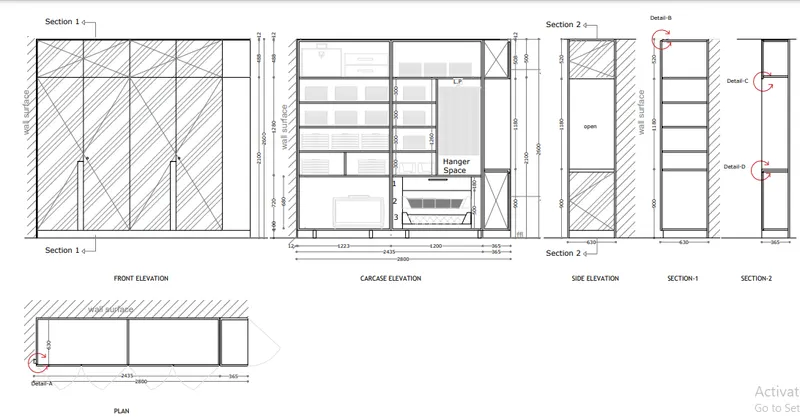
- To draw the elevation and details of the wardrobe as given in the below figure and to provide the dimensions and text with the use of layers.
Procedure:
- Initially set the units as decimal (millimeters).
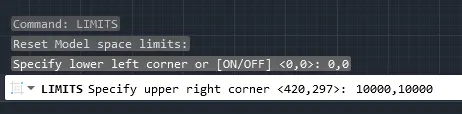
- Now, set the limits of the drawing:
- Specify the lower left corner: (0,0)
- Specify the upper right corner: (10000,10000)
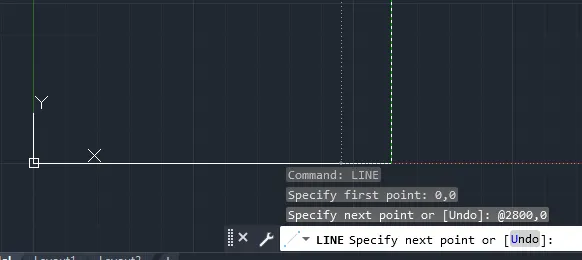
- First the plan of the drawing is developed using line command. So, choose the line command:
- Specify the first point:(0,0)
- Specify the next point: @2800,0
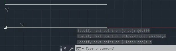
- Specify the next point: @0,630
- Specify the next point: @-2800,0
- Specify the next point: C
- Choose offset command to offset all the edges at an offset distance 20mm inwards.
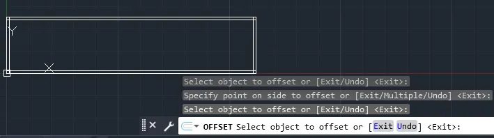
- Now, trim off the unwanted portion:
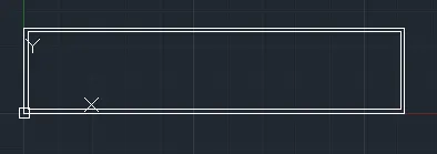
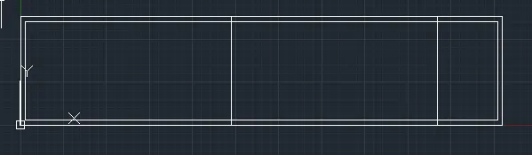
- Now, againn choose the offset command and offset the line at the left side at an offset distance of 1223mm now again offset this line at an offset distance of 1200mm.
- Now again offset the recently drawn line at an offset distance of 20mm on either side for the right line and an offset distance of 15mm on either side for the left line.
- After this, trim off the unnecessary line and use extend, if needed.
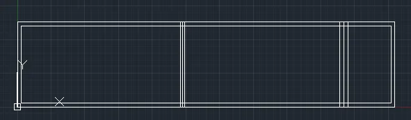
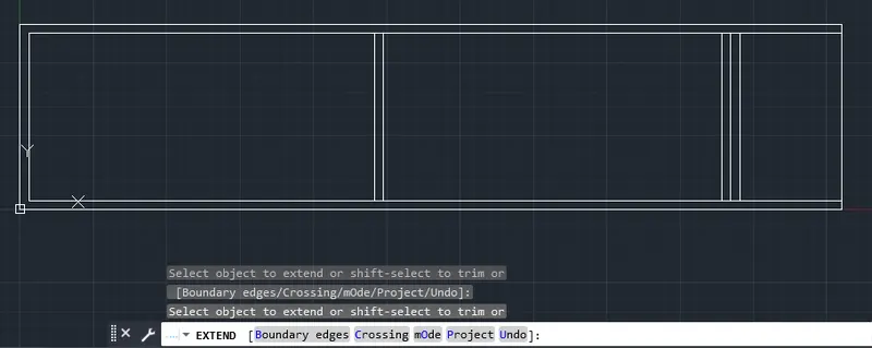
- Now, using line command mark the door portion for both the doors.
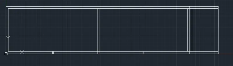
- Using the trim extend command complete the remaining figure.
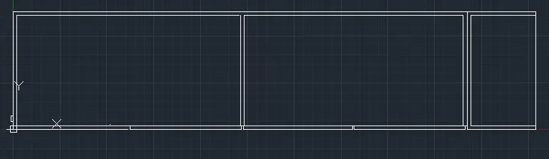
- Now, using the line command, hatching for the wall surface is done.
- After hatching, these lines are made dim by increasing its transperancy value to 70.
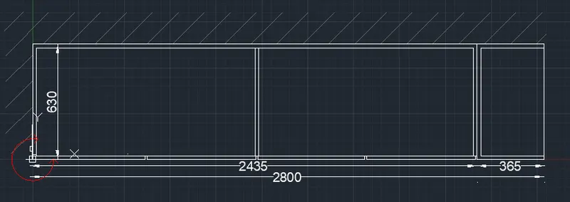
- After this, the plan is completed by dimensioning and providing the necessary text.
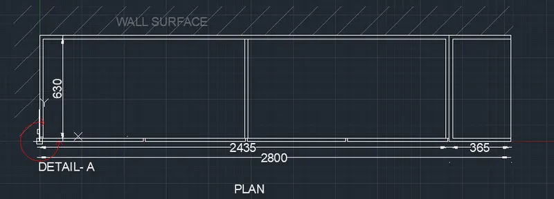
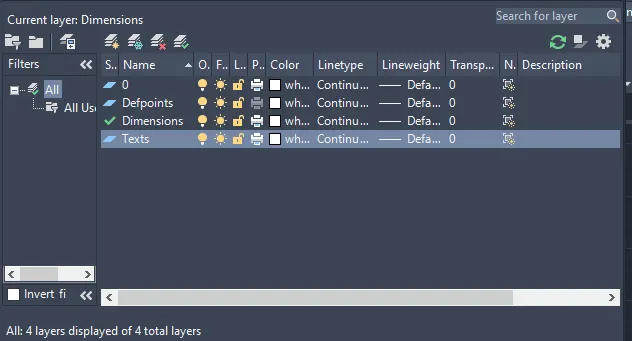
- Texts and dimensions are assigned as different layers, named as text and dimensions.
- Hence, the plan is completed. Now, front elevation can be developed.
- For that construction lines can be used to elevate the elements in plan.
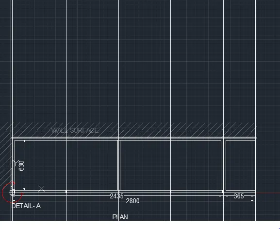
- Now, use the construction line option to draw the horizontal line to create the base of the wardrobe.
- The command used is XLINE.
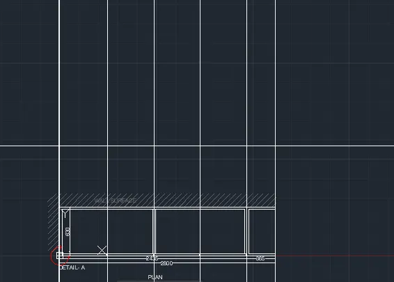
- Now, using the trim option, trim off the unwanted portion of the construction lines.
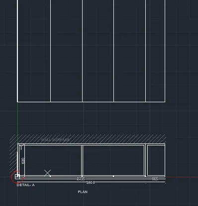
- Now, in the front elevation, offset the horizontal line drawn at an off set distance of 100mm upwards.
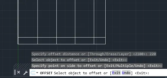
- Then, again offset bottom line at an offset distance of 2100mm.
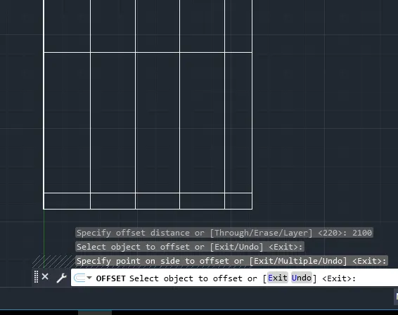
- Now, offset this line recently created at an offset distance of 488mm upwards, this line thus created is further offsetted at an offset distance of 12mm.
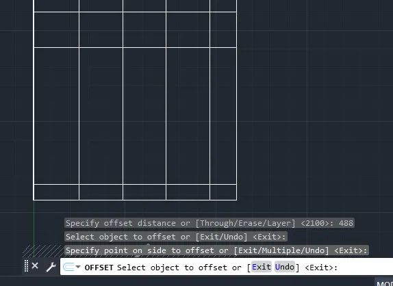
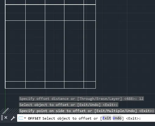
- Now, trim off the unnecessry part of the construction line.
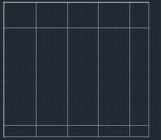
- Now, using the line command draw the cross bracings given in the front elevation of the wardrobe.
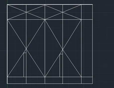
- The transparancy of these lines are then increased to value of 70.
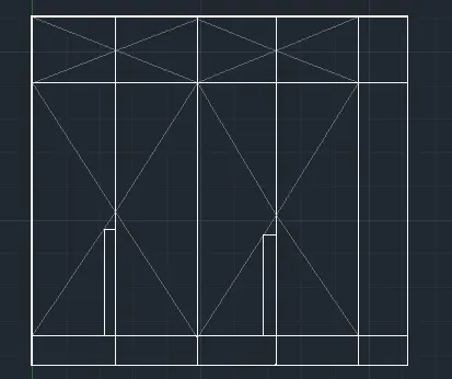
- After that draw the hatchings in the drawing using line command and offset command.
- The transparency of these hatching are also increased to value of 85.
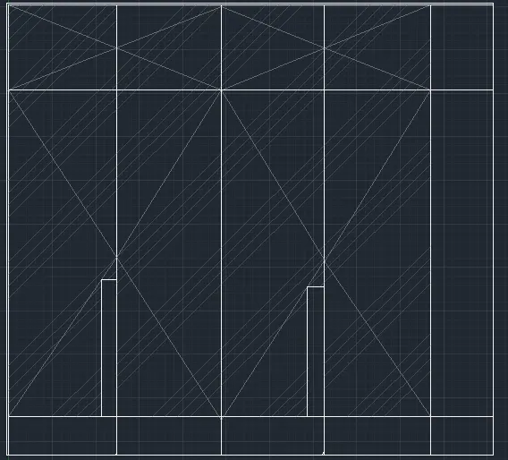
- Now, hatching for the wall is provided using line command and offset command (offset distance of 100mm).
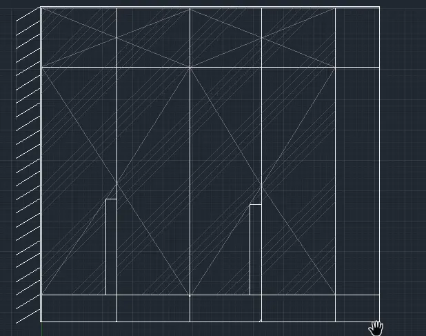
- This hatching portion is also made dim by increasing the transparency value to 70.
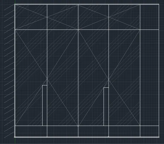
- Now, the figure can be completed by dimensioning it and adding necessary text.
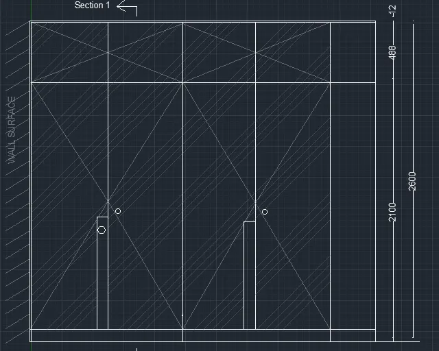
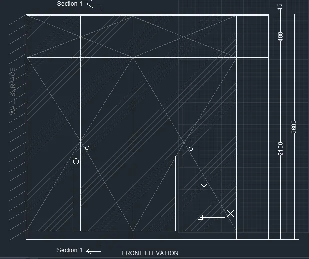
- After front elevation, next one to be drawn is carcase elevation.
- This has the same outline as the front elevation, the outine of front elevation can be copied and placed next to front elevation.
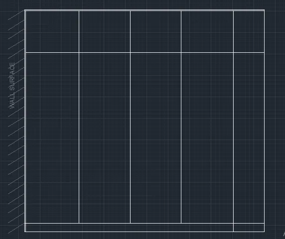
- Then all the lines are offsetted at an offset distance of 20mm inwards .
- The unnecessary part can be trimmed off using trim command.
- Then using the line command legs of the wardrobe can be created.
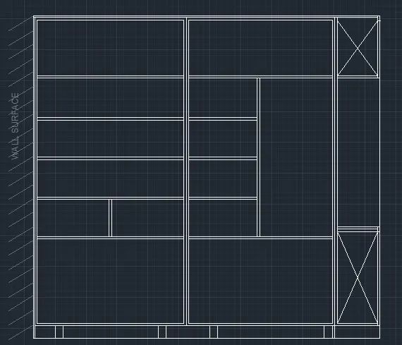
- Now, using the line command and rectangle command elements within the wardrobe can be created. Further, it is then made dim by increasing the transperancy.
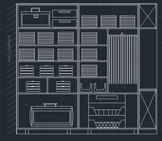
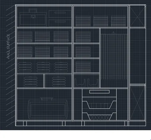
- Now, the figure can be completed by dimensioning nd adding necessary text within the drawing.
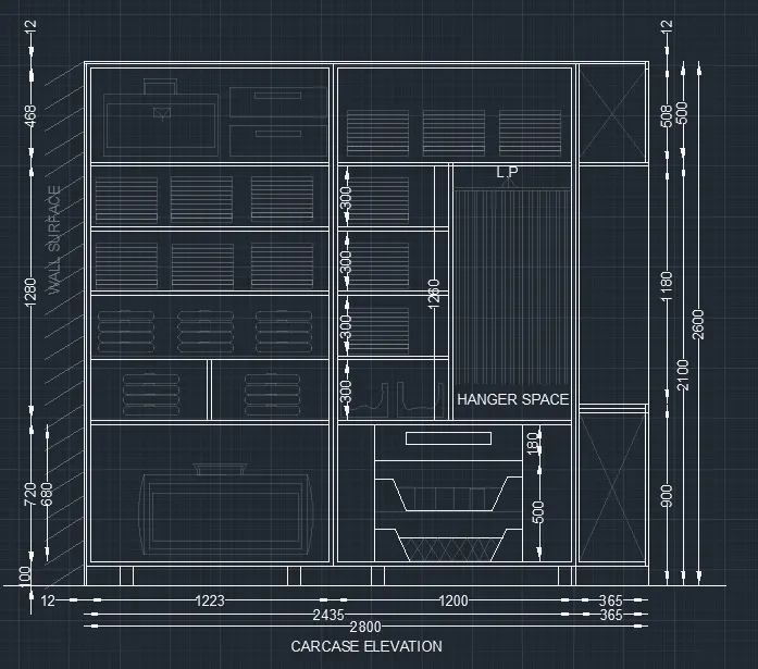
- Dimensions and texts are then placed in the respective layers.
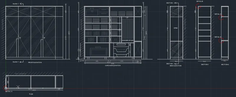
- Now, the next one to be drawn is the side elevation. For this choose the rectangle command, and draw a rectangle of size 630mmx2600mm.
- Then offset this rectangle at an offset distance of 20mm inwards.
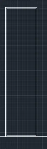
- Now, using the offset option divide the section into different portions.
- Then, using the line command do the hatching wherever required.
- The hatched part is then made dim by increasing the transparency value.
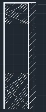
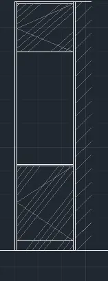
- Now, the figure is then completed by providing the dimensions and necessary texts.
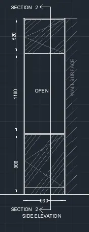
- Dimensions and texts are then placed in the respective layers.
- The next one to be drawn is the detailing of section 1. For this, first the outline of the side elevation is copied next to it.
- Then using the line command different drawers are made.
- Then the figure is completed by dimensioning it and providing necessary texts witin the figure.
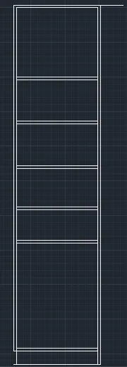
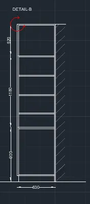
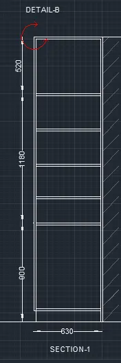
- Dimensions and texts are then placed in the respective layers.
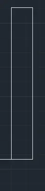
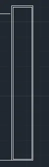
- The next one to be drawn is the section 2 of the figure, for this draw a rectangle of size 365mmx2600mm size using the rectang command.
- Offset this rectangle at an offset distance of 20mm inwards.
- Then using the line command complete the outline of the section.
- Finally dimensions and texts involved are added to the drawing.
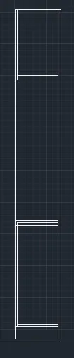
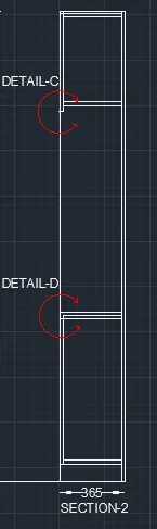
- Hence, the entire drawing is completed and is obtained as given below:
2.
Aim:
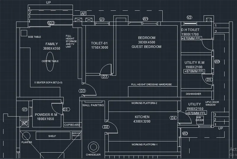
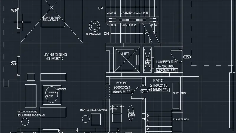
- To sketch the floor plan as given in the figure using proper drafting tools.
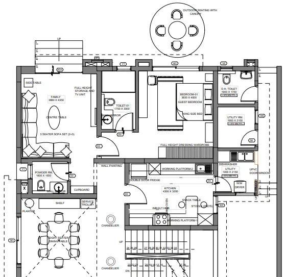
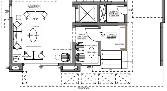
Procedure:
- Initially set the units as decimal (millimeters).
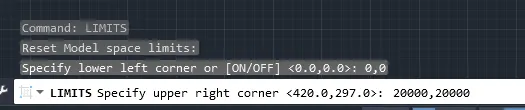
- Now, set the limits of the drawing:
- Specify the lower left corner: (0,0)
- Specify the upper right corner: (20000,20000)
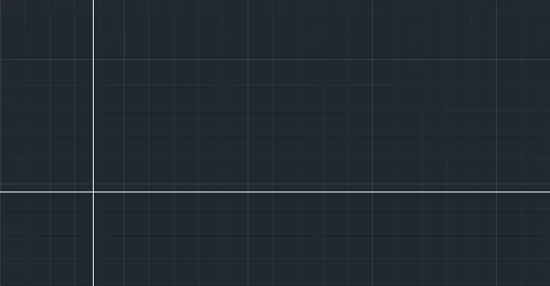
- Using the command Xline in command prompt, draw two construction line horizontal and vertical; this forms the corner of the plan.
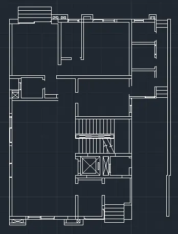
- Type offset in the command prompt and then offset the lines and hence different rooms of the plan can be created.
- Now, draw the dotted lines by changing the linetypes to dash lines wherever required.
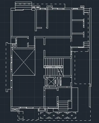
- Draw the doors using arc option.
- Now, complete the figure by providing the text and dimension.
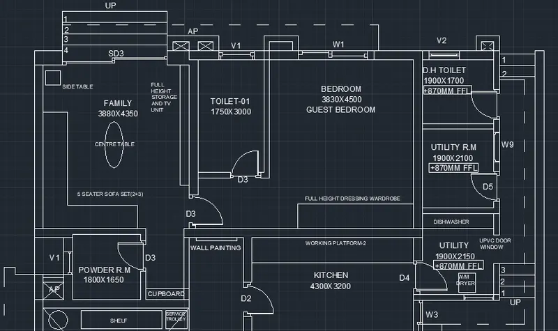
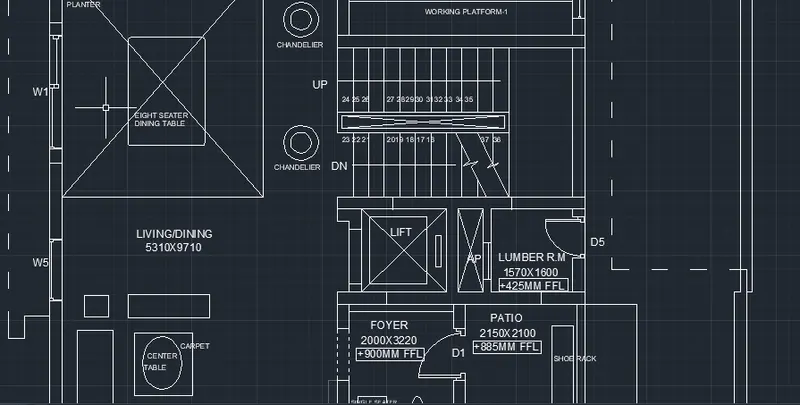
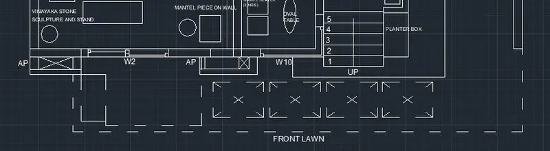
- Completed figure is given below:

3.
Aim:
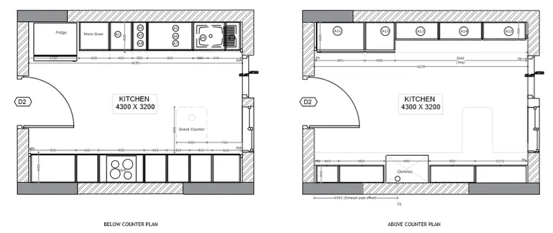
To create the kitchen layout as given in the figure and by using proper dimensioning technique dimension the layout and insert the text wherever necessary.
Procedure:
- Initially set the units as decimal (millimeters).
- Now, set the limits of the drawing:
- Specify the lower left corner: (0,0)
- Specify the upper right corner: (11000,11000)

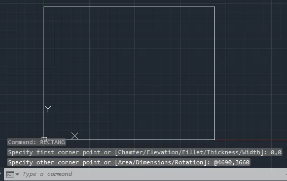
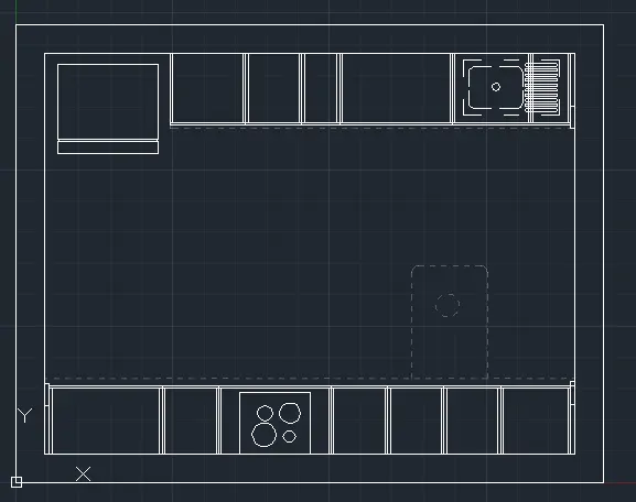
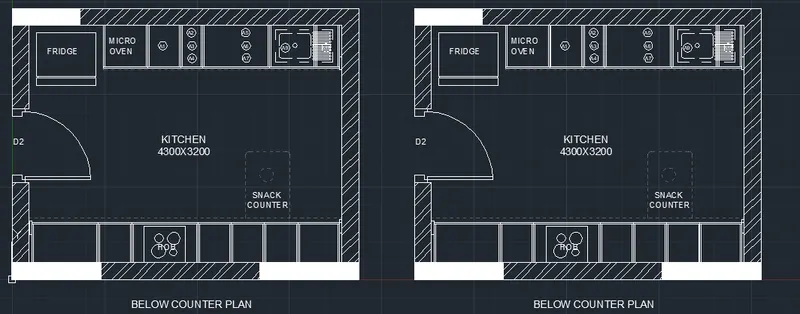
- First, drawing the below counter plan. For that, choose rectangle command and draw rectangle specifying the dimension as 4690mmx3660mm.(230mm+230mm wall is added on either edge)
- Now, offset this rectangle at an offset distance of 230mm inside which creates the wall of the layout.
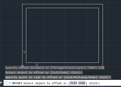
- Now explode the inner rectangle to make it into individual lines.
- Offset the upper and lower line at at offset distance of 600mm inwards.
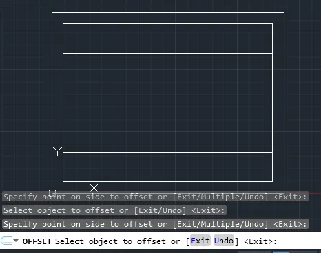
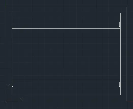
- Initially draw a small rectangle having width 35mm which is placed adjacent to walls to provide a gap between the counter and the walls.
- This rectangle is then copied to all sides wherever it is to placed.(all the counters should be plced within the 600mm portion created earlier.
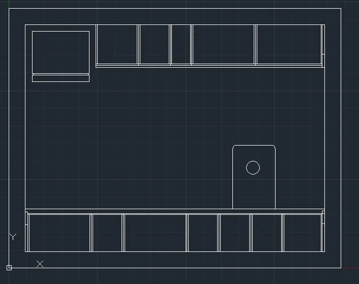
- Now using the line command draw different cabinets of the kitchen.
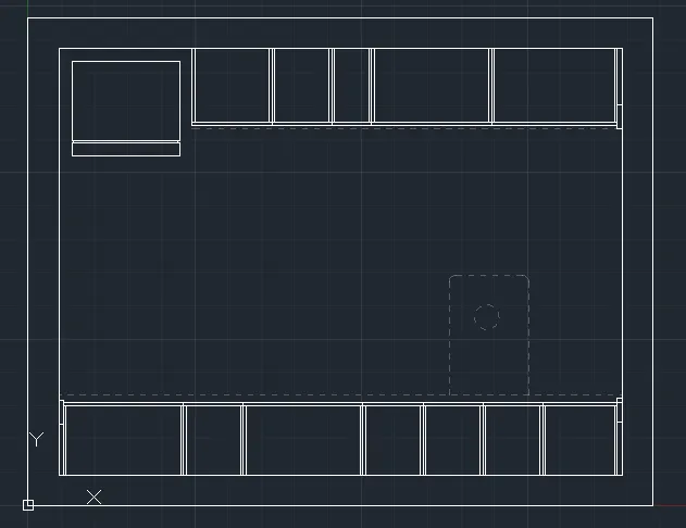
- Change the line type for those lines which are to shown as dashlines. This can be changed in the properties panel of the ribbon. Click the dropdown panel of linetype and change the line type. (For snack counter and slab).
- After that make it dim by increasing the transprency value.
- Now, using the circle command draw the hob.
- Then fix the sink in the provided location which drawn using line arc and circle command.
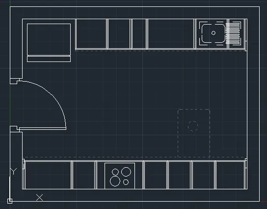
- Fix the door of the kitchen using tools like lines, circle.
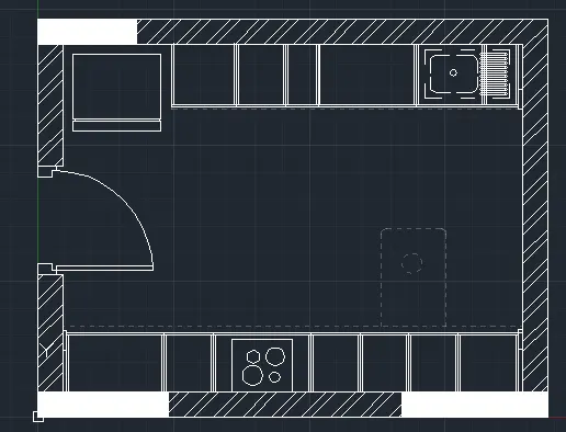
- Hatching is provided to the walls of the kitchen to represent it as a brickwall.
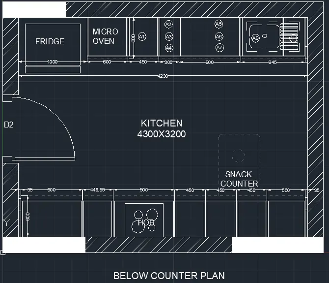
- Now, to complete the figure, texts and dimensions are included.

- Completed figure is given below:
- Now we have to develop the above counter plan in the same as the below counter plan.
- For this, initially copy the below counter plan adjacent to it so that we can achieve the out line of the above counter plan from it.
- Then the interior part of the below counter plan is erased and is changed according to the above counter plan.
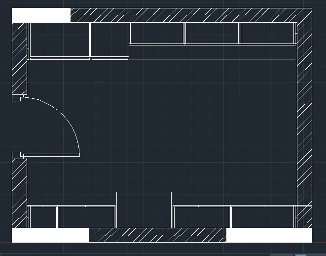
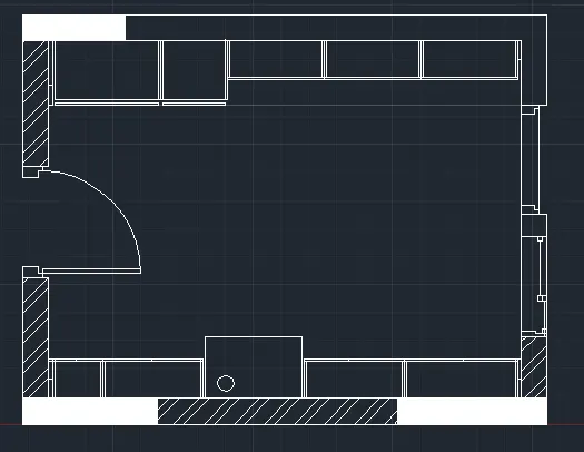
- Now, chimney and windows of the kitchen are marked.
- Now, include the text wherever it is necessary.
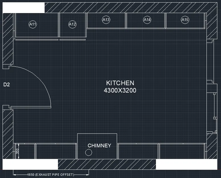
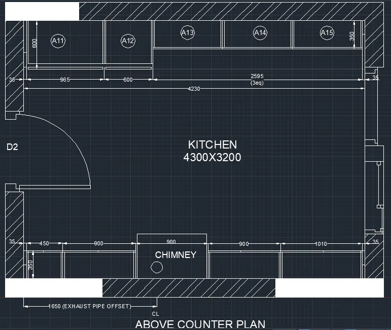
- Hence, the entire drawing is completed.
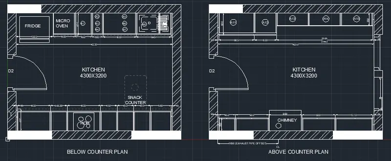
4.
Aim:
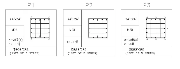
- To sketch the column details as given in the following figure:
Procedure:
- Initially set the units as Architectural (feet and inches).
- Now, set the limits of the drawing:
- Specify the lower left corner: (0",0")
- Specify the upper right corner: (20",20")

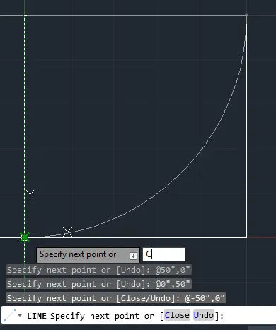
- Now choose line command to draw the table of the column schedule.
- Specify first point: 0",0"
- Specify the next point: @50",0"
- Specify the next point: @0",40"
- Specify the next point: @-40",0"
- Specify the next point: C
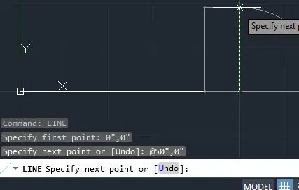
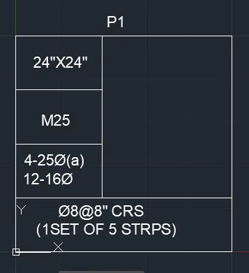
- Now, using line command draw different rows and columns.
- Similarly create two more tables. This can be done easily using copy option.
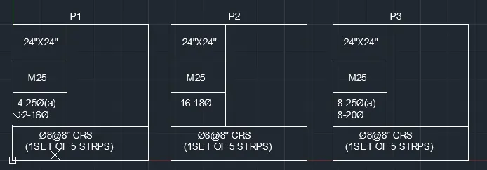
- Now, we have to draw the reinforcement details within the space provided above.
- So for that choose the line command and circle command to draw the reinforcement details.
- Conversion of mm to inches:
- 8mm-0.31 inches
- 16mm- 0.62 inches
- 20mm- 0.78inches
- 25mm-1 inches
- Initially using line outline of the column plan is created.
- Then, offset these lines at an off set distance of 1.5" inwards.
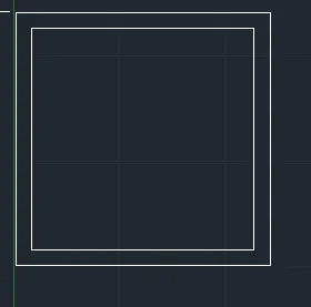
- Now, using the circle option draw the reinforcements.
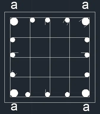
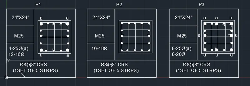
- For P1, corner bars are having diameter of 25mm and other bars 16mm.
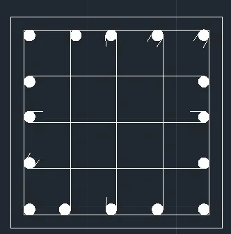
- For P2, all bars are having diameter of 18mm.
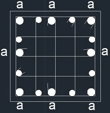
- For P3, 8 bars are having diameter of 25mm and other 8 bars has a diameter of 16mm.
- P1, P2 and P3 are drawn respectively as follows:
- These reinforcement details are then placed in their respective columnsin the above drawn tables.
- Hence, the final drawing obtained is as follows:
5.
Aim:
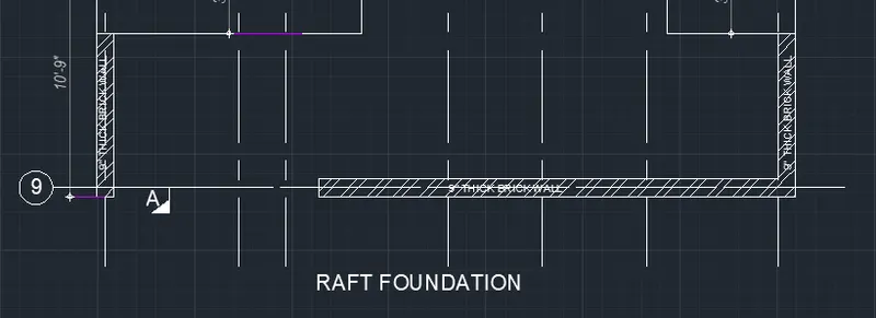
- To draw the raft layout as given in the figure:
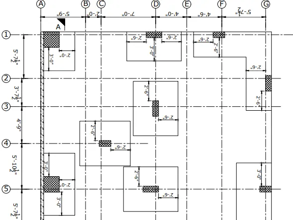
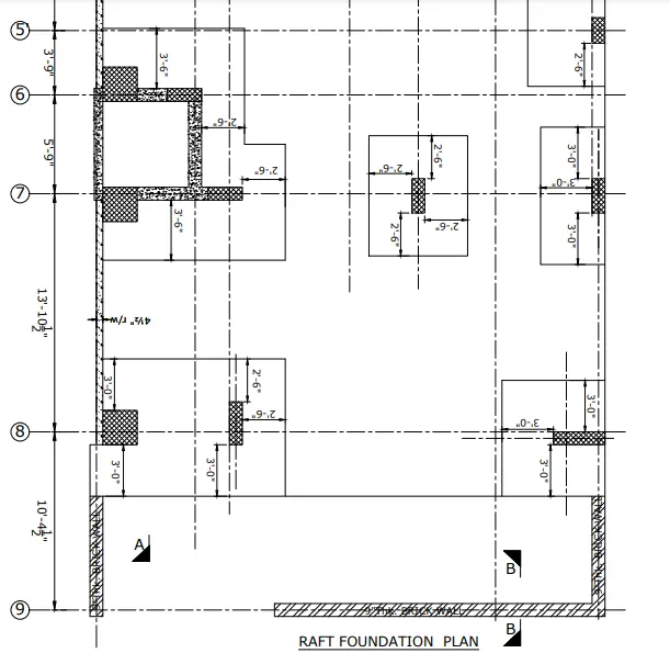
Procedure:
- Initially set the units as Architectural (feet and inches).
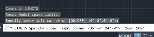
- Now, set the limits of the drawing:
- Specify the lower left corner: (0',0')
- Specify the upper right corner: (100'0",100'0")
- Now, choose rectangle tool and draw a rectangle of size 29'7.5"x60'0".
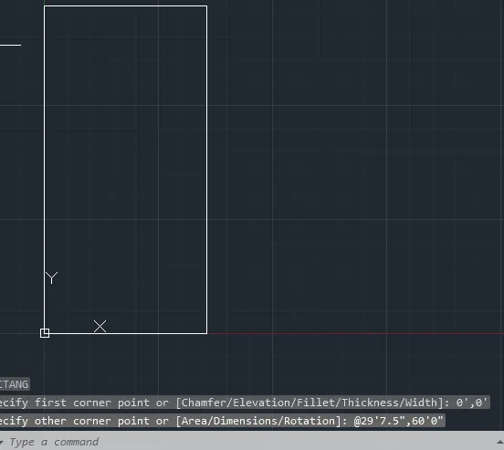
- Now, in properties panel change the line type to center 2 inorder to obtain dotted line.
- Using this lines draw the grid lines by offsetting each line at the prescribed distance in both horizontal as well as vertical direction.
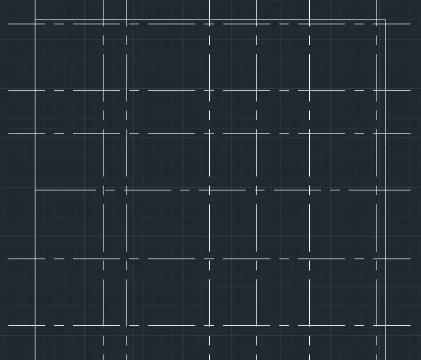
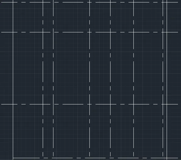
- Now, using the offset option offset the left most line at an offset distance of 4.5"(first explode the rectangle to individual lines). So for this, it will be better if we make the grid lines layer invisible.
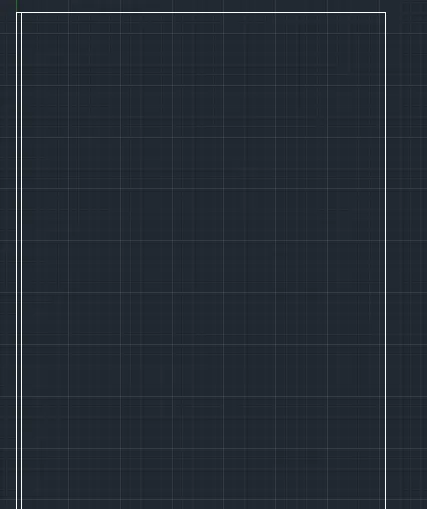
- Now, switch on the grid lines layer .
- Now, use rectangle command and draw the columns in the foundation.
- Various column sizes are: 24"x24"; 9"x24"; 9"x18"; 9"x30".
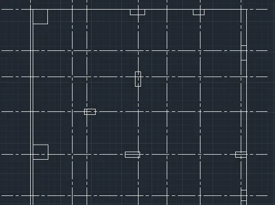
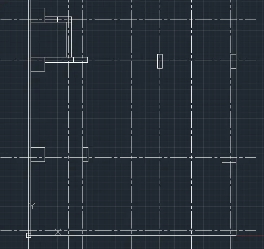
- Hence, columns are drawn. Now, we have to draw the footings for these columns.
- Using line command the footings for these columns are created.
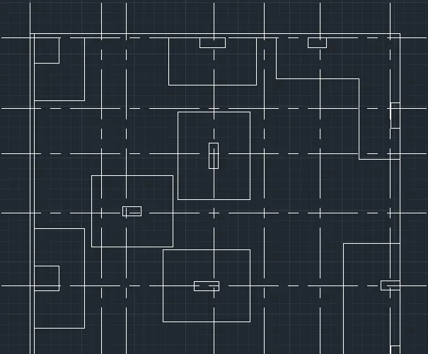
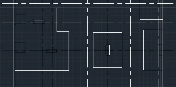
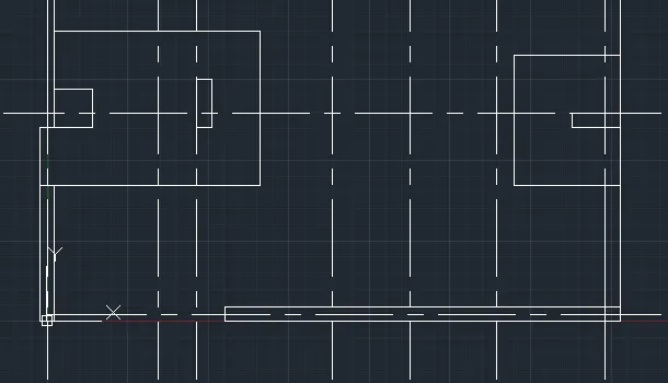
- Now, using the hatch option hatching is done with respective hatch pattens for columns, brickwall, concrete portion.
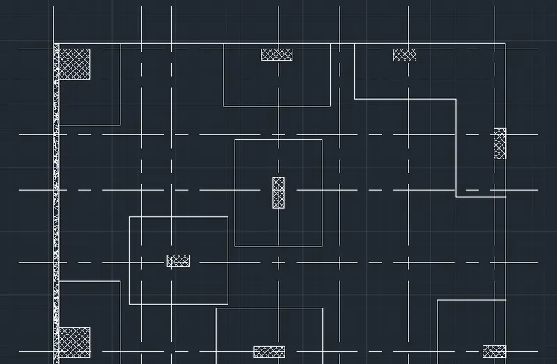
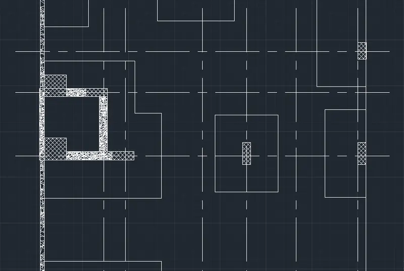
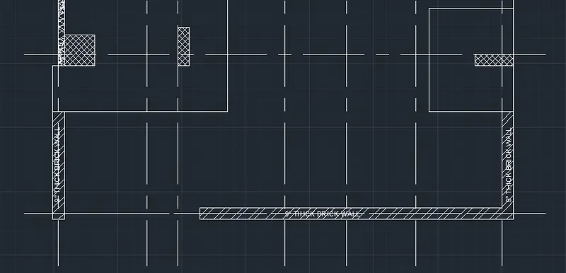
- Now the figure is completed by poviding the necessary texts and dimensions.
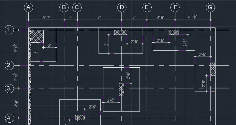
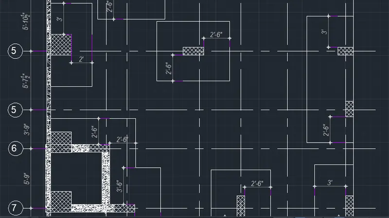
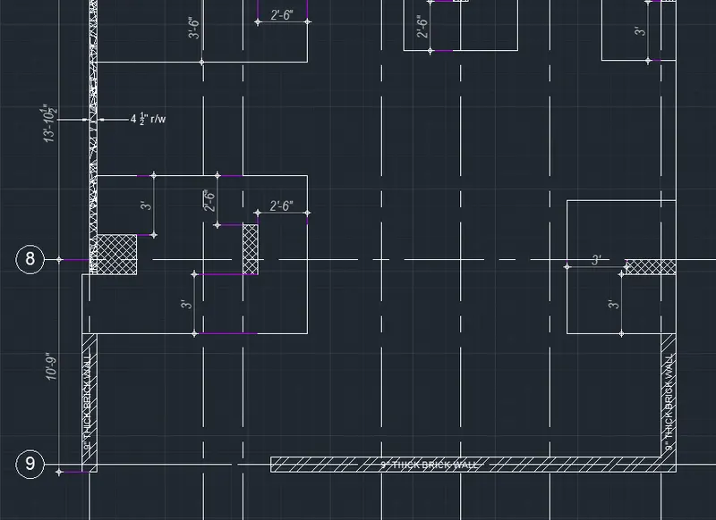
- Hence, the completed drawing is given below:
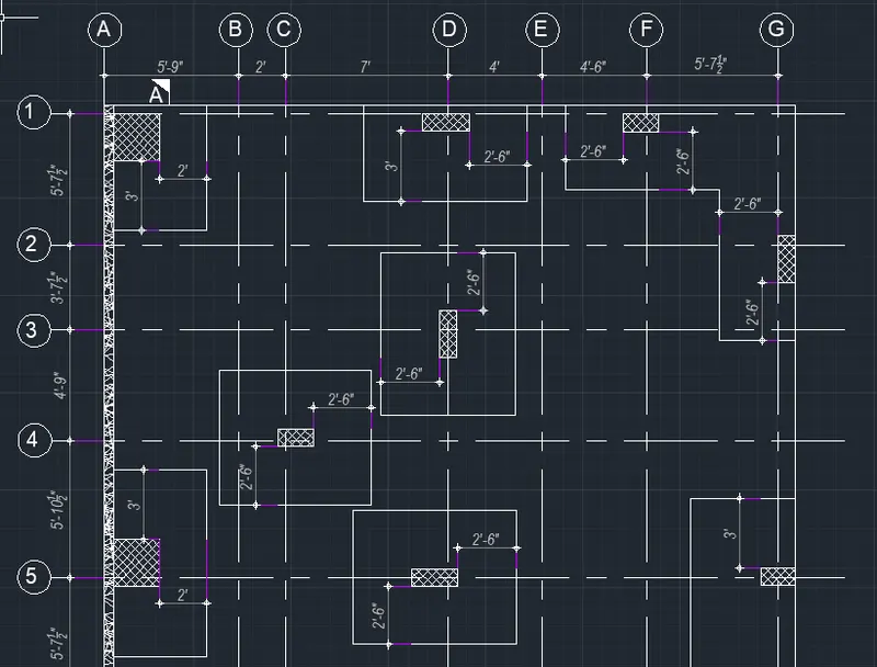
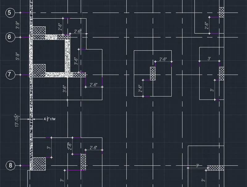
Result:
1. Details of a wardrobe:
- Front elevation:
- Cascade elevation:
- Side elevation, Section 1 and Section 2:
- Complete figure:
- Different layers created: Except texts and dimensions all other objects are included in 0 layer.
2.
Floor plan using drafting tools:
3.
Kitchen layout:
- Below counter plan:
- Above counter plan:
- Complete figure:
4.
Column detail:
5.
Raft foundation: