Creating a Residence Layout, Seating plan, Toilet and Utility room plan using AutoCad
Q.1) Residence Plan:
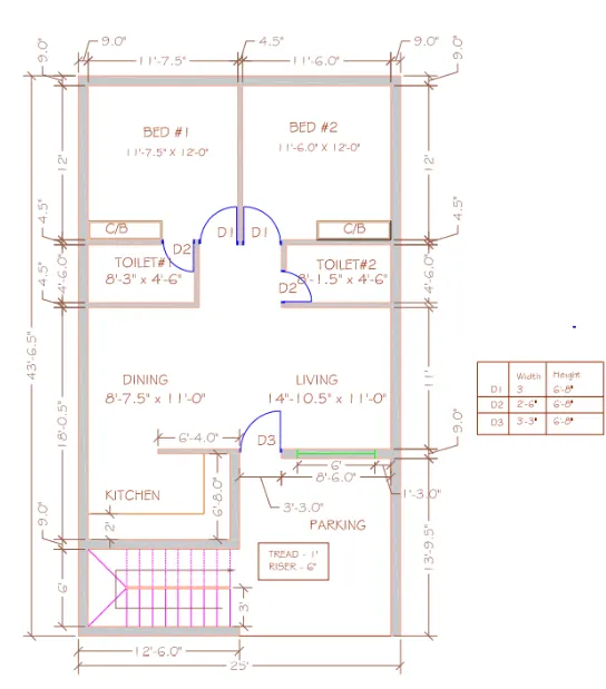
Sketch the layout of a residence as shown in the Figure 1. Consider all dimensions as reference to sketch the unit plan. Also the text in the layout are only for reference. Assume the missing dimensions. Also, refer the schedule for size of the doors.
ANS.
- SOFTAWARE USED : AUTODESK AUTOCAD 2023
AIM: To draw a residential plan using AutoCAD software.
PROCEDURE :
- First the open the software
- Give the command QNEW and press the ENTERE key
- Click on imperical templete
- Select ADVANCE SETUP
- Unit : Engineering , precision :0’-00”
- Angle :decimal degree , precision :0.00
- Angle measure : East
- Angle direction : Closkwise
- Area : 20*20
- And finished
- Command :LIMMX >70',70'
- Command :LIMITS >0',0>Upper Right Corner>70',70'
- Command : Z ( zoom ) command all
- Let’s start
Draw the external walls:
- Draw the constrcution lines by command "XL-V" for vertical and "XL-H" for horizontal.
- Create an offset from vertical line at a distance 25' and horizontal line at a distance 43'-6.5" by give the command of "offset".
- Command "0" - select the line and give offset distance as 9" at inner side of rectangle by 3sides.
-Now we satrt from left top corner of Rectangle
Draw the bedroom 1 and 2:
- Give the command "O"- specify offset distance 11'-7.5" and select the object from 9" in vartical direction and press enter - Specify point on side to offset on right side
- Type 'O' and press enter or click offset from the modify tool bar.
• Specify offset distance: Type 4.5" and press enter
• Select object to offset: Select the last offset line and click on right side
- Type 'O' and press enter or click offset from the modify tool bar. for draw horizontal line.
• Specify offset distance: Type 12' and press enter
• Select object to offset: select the object from 9" in vartical direction line and click on downward side
- Again give offset of 4.5" to this line so that will thickness is created which is internal wall of b/w bedroom and wc
Drawing toilet 1 and 2
- Type 'O' and press enter or click offset from the modify tool bar.
• Specify offset distance: Type 4'-6" and press enter
•Select object to offset: Select the last offset line and click on downward side
- Now again for draw inertnal wall give command 'O' for offset and press enter
• Specify offset distance: Click in the horizontal direction Type 3' and press enter.
• Select object to offset: Select the internal right side wall of bedroom and click right side so again select internal left side wall of bedroom and click right side.
- Type 'O' and press enter or click offset from the modify tool bar.
• Specify offset distance: Type 4.5" and press enter
• Select object to offset: Select the last offseting objects click on inner side .
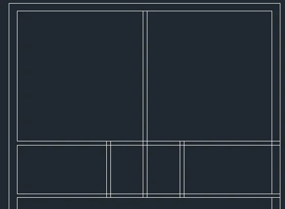
- Again give offset of 2'-6" vertically in toilet 1 from vertical wall having thickness is 4.5" in left side and horizontally in toilet 2 from downward wall having thickness is 4.5" in upward direction so this line so that will door space is created.
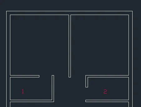
- Trim unwanted portions in vertical and horizontal direction.
Draw the living room , Dinning and kitchen:
- Type 'O' and press enter or click offset from the modify tool bar.
• Specify offset distance: Type 11' and press enter
• Select object to offset: Select the outer portion of toilet 1 wall and click downward side. after that select multiple option in command box and give the offset from toilet 2 in downward direction.
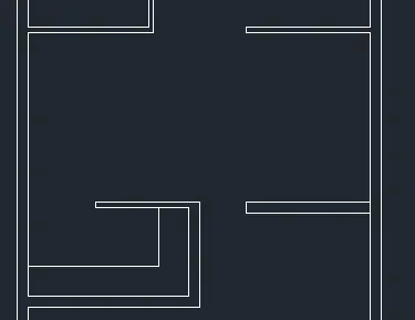
- Give line command and draw line in -y direction having length is 7'-9.5" so give this value and enter. Then put value 11'-9" in -x direction this draw upto the wall.
-Give command 'O' and press enter
• Specify offset distance: Type 4.5" and press enter
• Select object to offset: Select the top side wall and click inner side.
- Again create offset having specify offset distance is 9" select object to offset and give the offset inner side of bottom and right hand side wall. Also for living room wall give offset at outward direction which is join these two lines by drawn line. for draw line click line option from the draw tool bar.
- Now for draw the kitchen platform also give offset 2' from inner side of wall by both dirction horizontally and vertically and after that by using option of fillet join this platform.
- Making door for kitchen from inner side wall give offset in left side at a distance 6'-4". Trim unwanted portion.
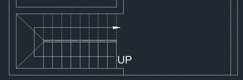
Draw staircase:
- Type 'O' and press enter or click offset from the modify tool bar.
• Specify offset distance: Type 6' and press enter
• Select object to offset: Select the outer wall of kitchen and click downward direction
- Give a wall thickness of 9" for the staircase room. Join this wall by drawn line giving command 'L' for line
- For dividing the staircase give an offset of 3' from the front wall thickness. Give offset of 1'(thread) to draw the stairs in plan view.
- Draw 9 offsets as there are 9 risers for 8 steps.
- Trim the lines between handrails by 'TR' and give the other side as dotted line which indicates it is 1st floor stairs which is not visible when viewing ground floor plan view.
- Show the direction of going upward by using qleader- select setting > section of leader line and arrow change the no of points which are 4 then ok and draw leader and give text 'UP'
Draw the window:
- For living room take an offset of 1'3" as given in the figure.
- Using line command draw a line of 6' from the centre of offseted line inside the wall thickness.
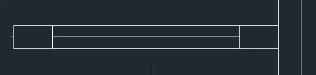
Draw the doors:
- Create the opening for respective doors using the width given in the table.
- Creating an hinge of 2" . Draw a line by command "L" in x direction 2"- y direction 1"- (-x)direction 1" - y direction 1" - (-x) direction 1"
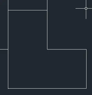
- Mirroring this hing by using command mirror 'MI' and specify base point and erase the source object > NO
- Now copy both object by type 'CO' 2 times and place it required gap distance b/w 2 hinge i.e. 2'-6", 3', 3'-3"
- Create lines by 'L' and draw in vertical directions from the end of hinge having lengths are 6'-8"
- Then for draw arc select option start, end, radius > specify the start and end points then give radius according to door opening which are 2'-6", 3', 3'-3"
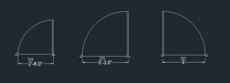
- Place this doors at center according to their space and at the midpoint of both the wall by using move command and 'CO' , 'ROTATE' where it required
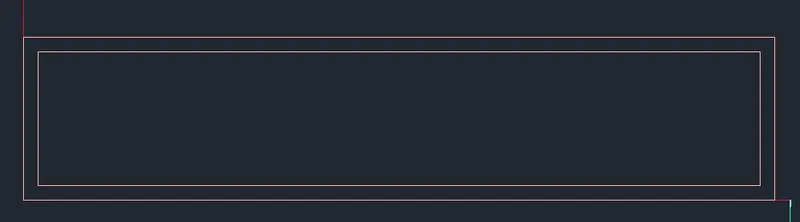
Draw the cupboard:
- Draw the cupboard by creating a rectangle specifying the base point and give dimensions as 5'-7" X 2'
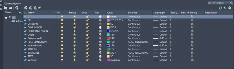
Layer creation:
- From layer property create new layer,create 6 layers each for wall,doors,windows,kitchen slab and cupboard,dimensions and stairs.
- Give different colours so that it can distinguised easily.
- Now select the objects and place it in individual layers.
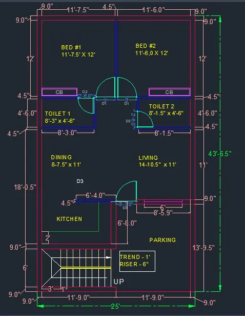
- Command :DIM (for dimensition ) , give the all dimension to all component of a plan
Result:
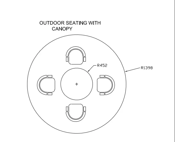
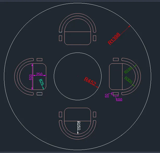
Q.2) Sketch the seating plan for an outdoor canopy. Assume the dimensions for the seating. Also, consider the dimensions in mm.
ANS:
Aim: to sketch the seating plan for an outdoor canopy.
- SOFTAWARE USED : AUTODESK AUTOCAD 2023
PROCEDURE :
- First the open the software
- Give the command QNEW and press the ENTERE key
- Click on imperical templete
- Select ADVANCE SETUP
- Unit : decimal , precision :0.00
- the dimensions in mm.
- Angle :decimal degree , precision :0.00
- Angle measure : East
- Angle direction : closkwise
- Area : 20*20
- And finished
- command : UN ( for units )
- units :mm , precision :0.0
- command :LIMMAX >100,100
- command :Z ( for zoom )
- Type : A FOR ALL
- press : ENTER
- lets start
Draw Circle :
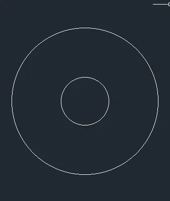
- With centre and radius method, circle is drawn
- Command "C" - specify the centre and give the radius as 1398 unit
- The inside circle is drawn with same centre and Radius as 452 unit.
Draw Chair:
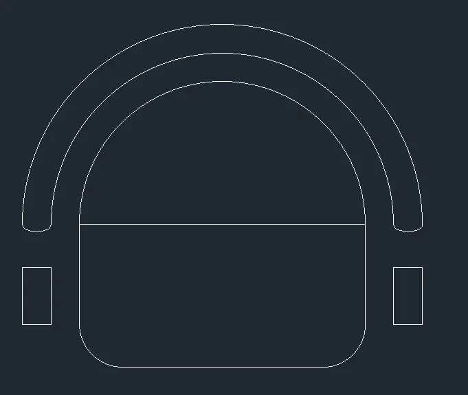
- Command "REC" click on the point where we want to create rectangle
- Give length as 500 units and width as 250 units
- With 2P method used for circle is drawn. Command "C"- select the both top corner of rectangle.
- Trim the unwanted arc of circle by using command "TRIM" select the unwanted arc and give enter.
- Using centre and radius method, circle is drawn Command "C" - specify the centre is the mid point of top side of rectangle and give the radius as 300. - Again select circle on draw bar give radius 350units and draw circle having same center.
- Draw line "L" and draw through the center of circles.
- Using command tr for trim below half arc of circles and this line also.
- Command 'blend' join these arc
- Now, Command "REC" - specify the point where we need to draw -click on "dimension" - here I have taken as length=50 units and breadth=100units.
- Using 'CO' copy the object and place the object at required place
- Then fillet the corners : Command "FILLET" click on radius and give the radius ,then select the two lines of which the corners are to be filleted.
-For the left and right side of the figure give 75 units as fillet radius
- Give Line command "L" draw the tangent for inner circle on four side and also draw Center mark by usine center command.
- For offseting using 'O' command select the line -give offset distance as 150 units.
- Copy this Chair and place it next to it with snap on, copy 4 of them.
- Command "Co" -select the object- select the base point - select the point where we need to place the Chair.
- Command 'ROTATE' - Select base point - Specify the rotation of angle 0,90,180,270 degrees and adjust according to their requirement match their geometric center and line.
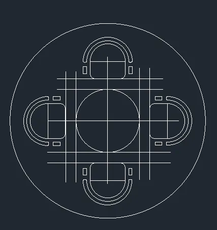
- Select the lines and press delet options for delet the lines
Create layers:
From layer property create new layer,create 8 layers each for Dimensions, chairs,circles etc
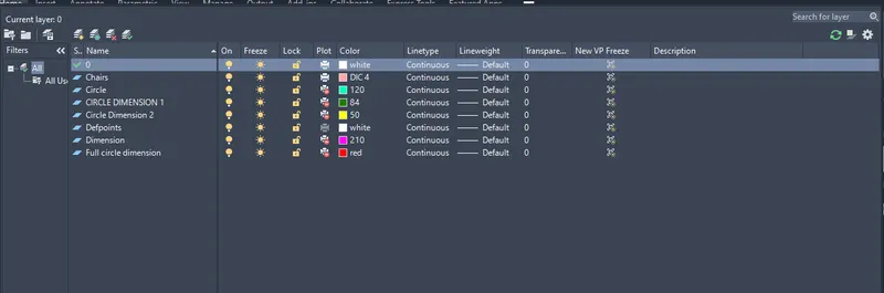
- Command :DIM (for dimensition ) , give the all dimension to all component of a seating canopy
Results:
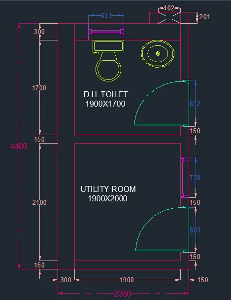
Q.3) Sketch the part plan for the toilers and utilities room. Consider the outer wall thickness as 300mm and inner wall thickness as 150mm. Also, assume the missing dimension, Texts, dimensions, and hatches are only for references. Also, symbols for toilets and w/c are also for references.
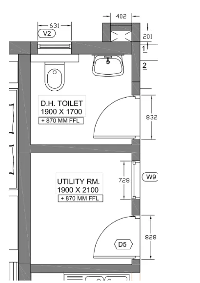
ANS :
Aim: to draw the part plan for the toilers and utilities room.
SOFTAWARE USED : AUTODESK AUTOCAD 2023
PROCEDURE :
- First the open the software
- Give the command QNEW and press the ENTERE key
- Click on imperical templete
- Select ADVANCE SETUP
- Unit : decimal , precision :0.00
- the dimensions in mm.
- Angle :decimal degree , precision :0.00
- Angle measure : East
- Angle direction : closkwise
- Area : 20*20
- And finished
- command : UN ( for units )
- units :mm , precision :0.0
- command :LIMMAX >100,100
- command :Z ( for zoom )
- Type : A FOR ALL
- press : ENTER
- lets start
Draw the utility room and D H toilet:
- With line tool draw the outline wall in form of rectangle of the rooms of 4400mm x 2350 with command "L"- specify the strat point, then draw 4400mm in + y direction - 2350 in +x direction 4400mm downwards and close.
- Draw an offset by using offset command having distance is 300mm from the right side of vertical construction line and downward direction from top. - For offseting using 'O' command select the line -give offset distance as 150 mm inner side from the bottom construction line and right construction line.
- Now draw an offset of 2100mm upwards from lower side wall. Again give offset of 150 to this line so that will thickness is created.
- Draw the box by offset command "O" with a distance of 402 respectively from the top outer side.
- Using'EX' command extend line upto last offset line.
- For join this line use fillet option. Command "FILLET" click on radius and give the radius is 0 ,then select the two lines of which the corners are to be filleted.
- Command "O" with a distance of 201mm respectively from the right inner side to left direction. Then give an offset Command "0" - 150mm select the left side from last offfset line.
- Trim the unwanted lines by using command "TRIM" select the unwanted lines and give enter.
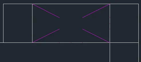
- Command "REC" click on the point where we want to create rectangle - Give length as 120 units and width as 60 units. Place it at center of 402mm x 201mm box then join both rectangle by line command 'L' - Delete this rect.
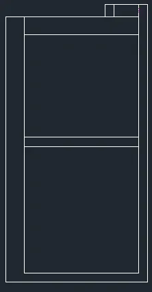
Draw the doors open space:
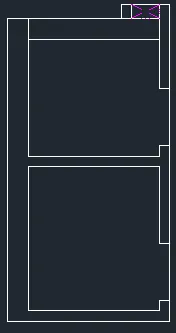
- From the bottom give an offset of 150mm,which marks the Open space for doors, Command "0" -give the offset distance as 150 in upward direction and select the bottom wall also select internal wall and give offset in upward direction
- Similarly, Create the rows by offseting distance of 832 and 828 from the last offsetting for the door opening. Trim off the unwanted lines.
Draw doors:
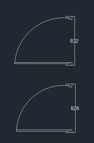
- Creating an hinge of 50 . Draw a line by command "L" in x direction 50 - y direction 50 - (-x)direction 50 - y direction 50 - (-x) direction 50 , Close by command 'c'
- Mirroring this hing by using command mirror 'MI' and specify base point and erase the source object > NO
- Now copy both object by type 'CO' 1 times and place it required gap distance b/w 2 hinge i.e.832 and 828
- Create lines by 'L' and draw in vertical directions from the end of hinge having lengths are 880
- Then for draw arc select option start, end, radius > specify the start and end points then give radius according to door opening which are 832 and 828
Place the Doors:
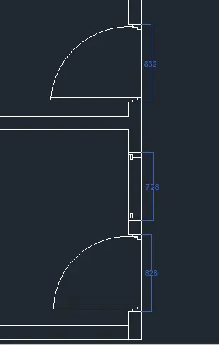
- Command 'Move' select object and its base point then move and place according to its postion.
Draw the windows:
Window 1:
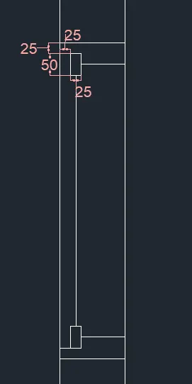
- By using line command draw a rectangle of length 150 and width 728 .
- Offset:command "O" and give the distance as 75 horizontaly to +y and -y direction.
- Command "0" -offset distance- 25 vertivally to +x and -x direction. select the object and create the rectangle.
- Trim the excess lines by command "TR" - select the bese point ( till where we want to trim) and seelcting the line we need to trim.
- Draw center line by command 'L' - slest center of rectangle and drag upto second traingle.
- Move this window with 'MOVE' option on 150mm from door.
Window 2
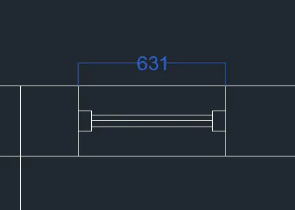
- Give 250mm offset from wall in right side directionby using 'O' for creation of window.
- Command 'O for' draw the window having length is 631
- Draw small rectangle at the both centere end of retangle by 'REC' command - dimensions 120mm x 85mm - press enter
- Delete outer portion of rectangle used 'TR' and trim it
- Create lines by 'L' draw at center of small rectangles
- Command 'O' with a distance 25 both side of centre line.
Create layer:
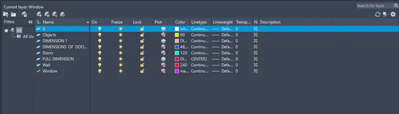
- From layer property create new layer
- Place the symbols for toilets and w/c from VIEW from Ribbon Bar > TOOL PALLET > ARCHITECTURAL > TOILET IMPERICAL, BASIN - place it at requird place
- Select their top views
- command 'SC' for increse size slect base point and Specify scale factor is 1.5 press enter
- Command :DIM (for dimensition ) , give the all dimension to all component of a plan
RESULT: