Creating a Residence Layout, Seating plan, Toilet and Utility room plan using AutoCad
1) AIM :
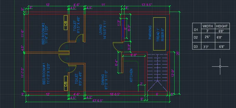
To sketch the layout of a residence as shown in the below fig. considering all dimensions as reference to sketch the unit plan. also the text in the layout are only for reference. assuming the missing dimensions. also, refering the schedule for size of the doors.
COMMANDS USED :
1.Units
2.Rectangle
3.Offset
4.Explode
5.Extend
6.Line
7.Copy
8.Rotate
9.Fillet
10.Hatch
11.Dim
12.Layer
PROCEDURE :
- Open the autocad software then give the units command and select the engineering units and inch insersion scale and precision 0'-0.00"
- In the command line type and line then specify the first point then along the x axis give the length 25' along y axis 43'-6.5" did the same lift side and created te rectangle as below.
- Give the command offset then give the offset distance 9" offset at every outer wall thickness.
- Give the trim command then trim the edges then again give the command offset command then give the every vertical distance like offset at distance 12' and the again give the distance 4.5" then 4'- 6.0" and 4.5" and then 11' offset and 4.5" then again 6.8" offset and 9" offset then click on cloe. after this step the drafted image shown below.
- Now offset the horizontal distance from the left side 11'-7.5" then again offset 4.5" then click esc.
- Trim the unnecessary lines as we required.
- Then separeate the rooms are provided dimensions then check the room dimensions. after the trim and separation of rooms the drafting fig below.
- Provide the door spaces by using the offset command and trim the unwanted lines.
- Now create the layers by using layer command and change the properties of lines like colour for different items like doors windows.
- Now we have different items like door, windows, cupboards, texts, dimensions. i have created these layers and when its needed changed the layer like if we need to draw the windows then we have to change the layers and select the door layers then the door layers properties will applicable while drafting.
- After then i have created the door block by 3 types and we click on insert command then where we have to provide the D1,D2,D3.
- Now give the command block then create D1,D2,D3.
- Door : Line command - specify the first point - door width - next point vertical direction door width esc.
- Give the rectangle command provide small rectangles at edges
- Give the arc command select centre, start, end arc then select the point create an arc.
13. If we have a multiple count of doors in same width we have create blocks then where we want we can easily insert by using insert command.
14. Now, mirror the create the two doors then move it specify the edge point.
15. Now in the same way we have to create the D2 then paste as specified location.
16. Now in the same way we have to create the D3 then paste the specified location.
17. Change the layer to create cupboard create the cupboard created by using rectangle command specify in the bed room.
18. To create the kitchen cabinate give the offset command of 2' distance and trim the projected lines.
19. Now to create the stair case change the layer type then by using offset command 1' distance give the multiple offset by the same distance its count as 9 offset. and give the command line then create a line at the centre off offsets line and then project at the corner point.
20. Give the command MULTI TEXT and then give the room names and then give the sizes of every room.
21. Change the layer give every dimensions by using DIM command. and also give the command hatch then fill the solid in the all wall thickness.
RESULT :
Sketched the layout of residence as shown in fig in below.
2) AIM :
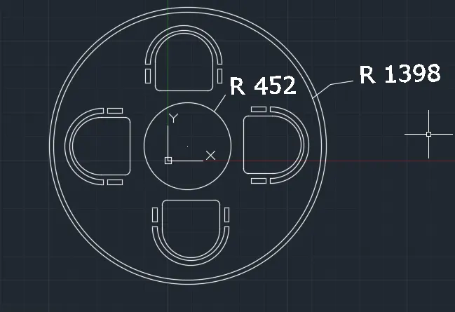
To sketch the seating plan for an outdoor canopy. assuming the dimensions for the seating also. considering the dimensions in mm.
COMMAND USED :
- Units
- Rectangle
- Explode
- Offset
- Line
- Copy
- Rotate
- Fillet
- Dim
- Layer
PROCEDURE :
1.Open autocad give the unit command select the decimal units and then precision 0 then select the intersection scales as mm then click on ok.
2. Give the circle command and give the radious of 1398 create a circle and again circle command give the radious 452.
3. To create a seat give the line command specify the point at out of circle then specify the next point at 500 mm and then vertical line at 300 mm distance.
4. Now give the arc command centre, start, end create an arc.
5. By using the fillet command and give the radius and fillet at corner points.
6.Give the offset command offset the arc and by giving the rec command create the hands.
7.Give the command block create the block and insert the required possion.
8.Create a circle for exact location for seat and put on the quadrent paste the seat at every quadrent of the circle then delete that circle.
9.Give DIM command to provide the dimension.
RESULT :
Sketched the seating plan for an outdoor canopy.assuming the dimensions for the seating also, considering the dimensions in mm.
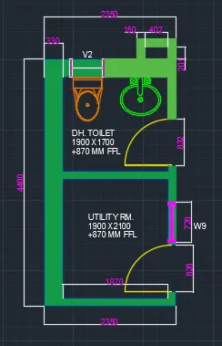
3) AIM :
To sketching the part plan for the toilet and utilites room. considering the outer wall thickness 330mm and inner wall thicknness as 150mm also, assuming the missing dimension,texts,dimensions, and hatches are only for references. also symbols for toilets and w/c are also for references.
COMMANDS USED:
- UNITS
- RECTANGLE
- EXPLODE
- OFFSET
- LINE
- COPY
- ROTATE
- FILLET
- DIM(DIMENSIONS)
- LAYER
PROCEDURE:
- Open autocad give the unit command select the decimal units and then precision 0 then select the inter section scale as mm then click on ok.
- Give the line command and specify the first point then give the vertical point 4400 and the horizantaldimension 2350.
- Give the offset command offset the outer wall 330mm distance and inner wall 150mm distance then trim the unwanted lines or intersection lines.
- Again give the command offset select the bottom line give 2100 distance again 150mm wall thickness. create the duct using offset command and trim command.
- Now create the doors and windows by using the line and offset command then by move it to require portion.
- Create the water closet and sink give the command DC> SAMPLE >EN->US>DESIGN CENTRE > HOUSE DESIGNER.dwg>blocks, drag and drop the toilet -top and sink -top scale then and move them to their respective possition
- Now by using the hatch command hatch the wall thickness. and give dimensions by usind DIM. command
RESULT :
Sketching the toilet and wash basin design of a toilets and the all dimension are in mm.