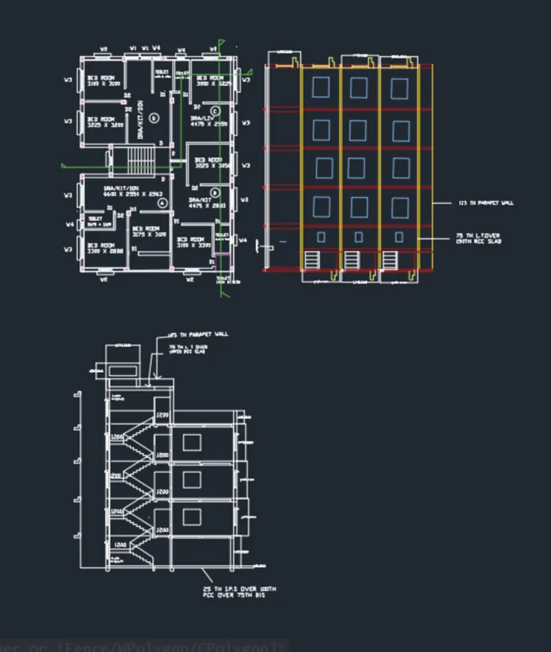
Creating a Layout, Section and Elevation with dimensions using AutoCad
Aim - To draw the Plan,Elevation and section of the building by using AutoCad Software
The dimensions -
For external wall -250mm
For internal wall - 125mm
For staircase - Thread = 250mm , Rise = 150mm
Windows -
W - 1000 X 1500
W1 - 900 X 1200
W2 - 1200 X 1200
W3 - 1500 X 1200
W4 - 700 X 500
Doors-
D - 1000 X 2000
D1 - 750 X 2000
D2 - 900 X 2000
Procedure - Click on AutoCad and open this application
- Type QNEW in command bar and enter
- Select default setting as Metric
- In default setting click on use a wizard and in that advance setting and set unit as decimal and precision as 0 and press next
- Set angle as decimal degree and precision as 0 and next
- Set angle measure as EAST and press NEXT
- Set angle direction as counter clockwise and press next
- Set area by providing length as 50 and width as 50
- Press finish
- Keep ORTHO and snap object ON
- Keep snap and grid OFF
- Unit to scale is Milimeter
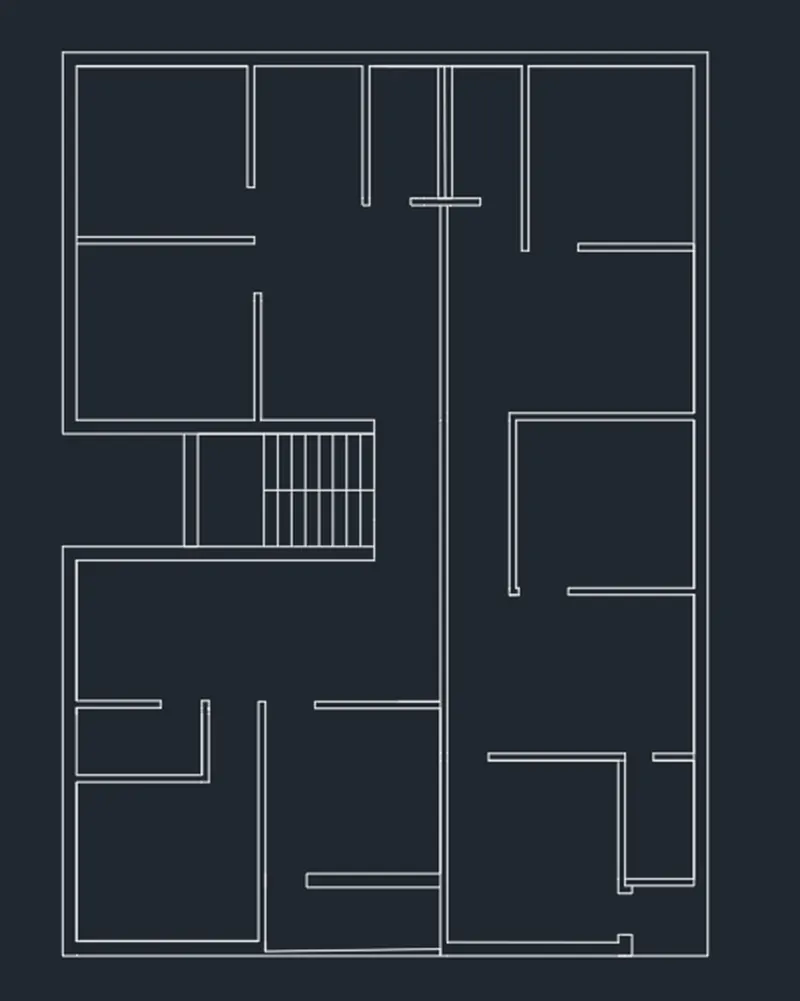
Step 1 - Take xline command
- Put xline horizontal and vertical
- Trim the negative coordinate
- Give the offset of 250mm to show the external wall thickness
- Offset the horizontal line at a distance of 1150,3138,3550,4488,9463,9713,12788,12193.16388
- Give offset to each horizontal line as per thire wall thickness
- For internal wall gie 125mm and for external wall 250mm
- Offset the vertical line at a distance of 3475,3675,5975,6850,7350,8725,10325,11700
- Give offset to each above vertical line as per their wall thickness
- Leave the space for doors as per dimension
- Take trim and rease command to remove the unwanted line
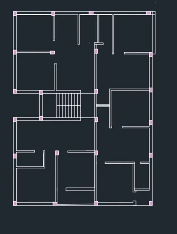
Step 2 - Take rectangle command to show column
- Specify its first corner anywhere out of drawing
- Select dimension
- Take length as 250 and width 400
- Take hatch command
- Click on dropdown
- Select hatche style as AR CONCR
- Click inside the rectangle
- Take copy command and select the object
- And place the column whereeven required
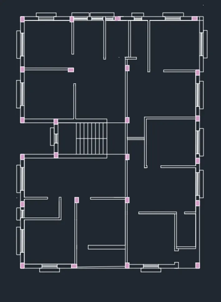
Step 3 - By using line command ,provide the doors and windows as per their dimensions
Step 4 - Click on Annotation tab
- Click on Dimension
- Click Manage dimension style
- Style name Challenge 7
- Set characteristic of dimension as
- Select Arrowhead size as 100
- Text height 200
- Then select linear dimension
- Provide the linear dimension having height 250mm
- Then take continuous dimension command and provide diemnsion
Result -
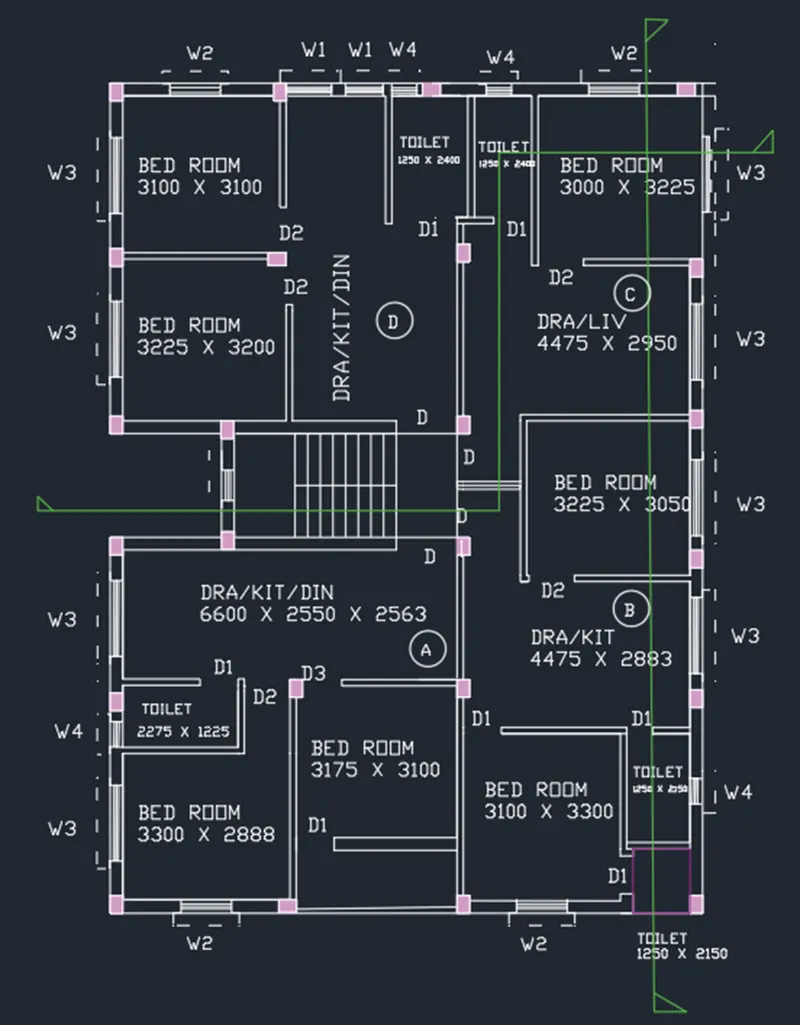
Section A-A -
Procedure -
Step 1 - Selcy the construction line tool by entering XLINE command in command tab
- Enter V
- Draw projection line fro plan created in step 1 and enter H
- Draw horizontal line at suitable distance
- Select the trim command and trim the unwanted lines
- Selct the offset command and offset the lines according to given drawing
- The vertical lines are offsetted to distance as per given room dimensions and wall thickness
- The horizontal lines are offsetted to a distance as per given room dimension and wall thickness
- The thickness of internal wall is 125mm and external wall is 250mm
Step 2 - Select the trim command and trim the unwanted line
- Selct the line command and draw the steps hhaving thread 250 and rise 143.75
- Select the copy tool and copy the stairs several times to create the flight of stairs
- Select the flight of stairs created and assign it to the stairs layer
- Craete the offset according to given drawing for doors and windows,the height of door is taken as 2100 and height of window is taken as 600 for smaller window and 1200 for bigger window
- Go to properties and change the line type to long dash short dash
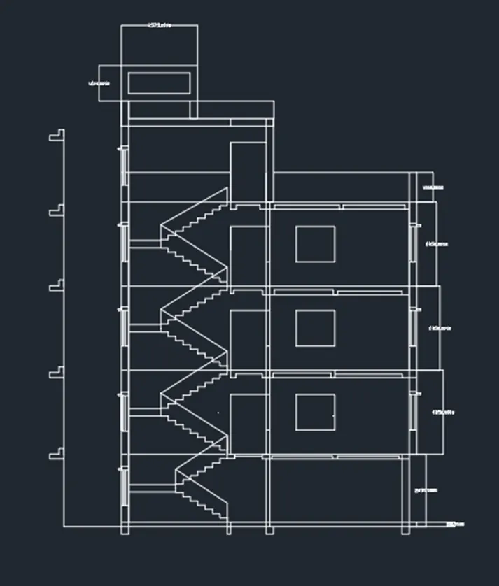
Step 3 - Selct the dimension tool by entering DIM in command line
- Select the first point and second point of the object to be measured,then drag the dimension line to the desired location.Repeat for all the object to be measured.
- Enter MTEXT command in tab and specify start point of text
- Scale the text to desired size
- Copy the text box whereever required
- Enter ED in command prompt and edit the text boxes as required
- In Annotataion panel ,go to multileader style manage,select the standard option,click on modify and make necessary chnages ,clisk on OK and set current
- select the Multileader tool and create multileader whereever required as per given drawing
Result -
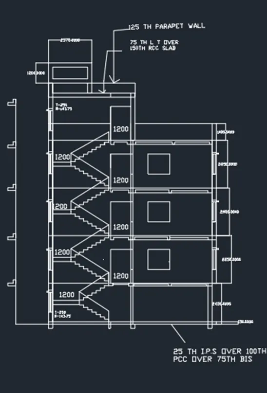
Section B-B -
Procedure -
Step 1 - Select the construction line tool by entering XLINE in command tab
- draw projection line from plan created in step 1
- Draw horizontal line at a suitable distance
- Select trim tool and trim the lines
- Select offset tool and create offset according to to given drawing
- The vertical line are offsetted to distanece as per given room dimension and wall thickness
- The horizontal Xline are offsetted to distance as per given room dimension and wall thickness
- While offsetting ,the thickness of internal wall is 75,125,150
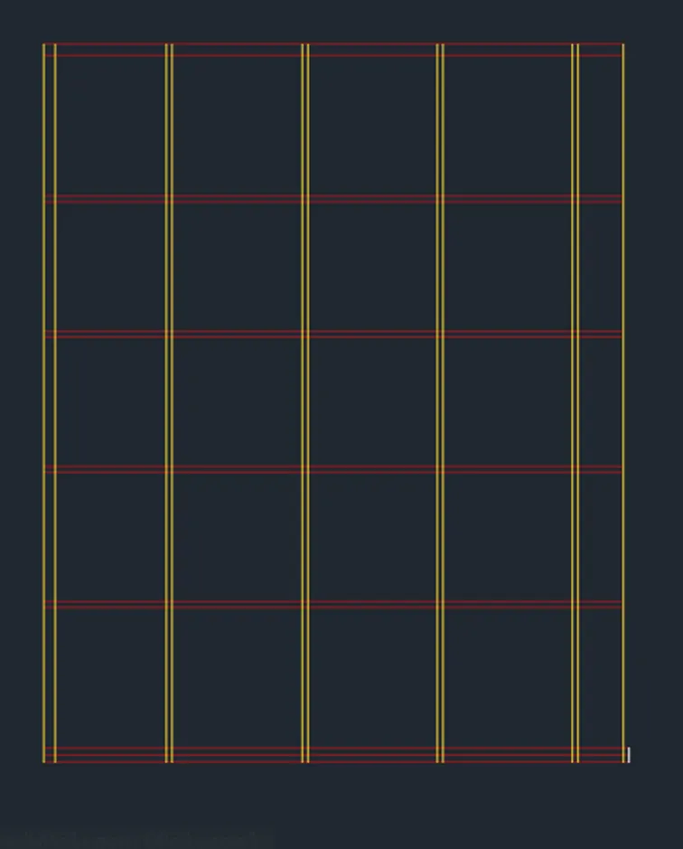
Step 2 - select the offset tool by entering OFFSET command
- Create offset according to drawing for doors and windows,the height of door is taken as 2100,and height of window is 600 and and for bigger window is 1200
- Select the trim command and trim the lines
- Select line tool and draw new section
- Go to properties and change line type to lond dash short dash
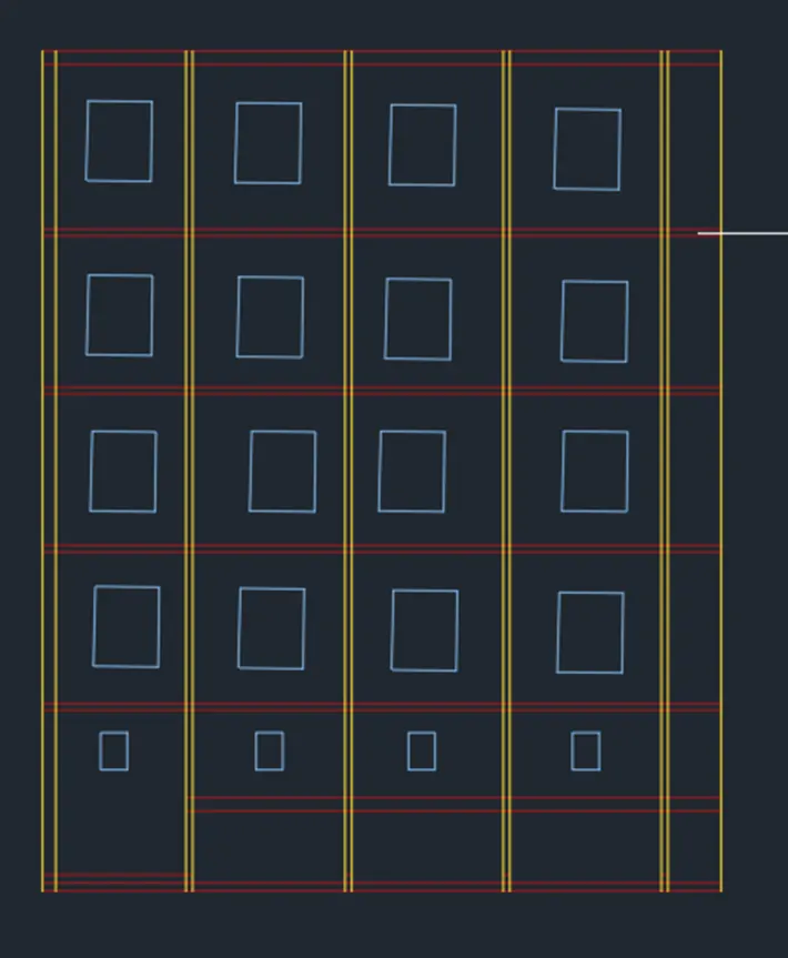
Step 3 - Select the dimension tool and select the first point and second point of object to be measured,then drag the dimensionline to desired location,repeat for all object to be measured.
- Enter Mtext in command box and specify first point of text as required
- Scale to the text to desired height
- Cpoy the text box whereever required
- Enter ED in command prompt and edit the text box
- In Annotation panel ,go to multileader style manager,select standard option,click on odify and make necessary changes ,click OK and set current
- Select Multileader tool and create multileader whereever required as per given drawing
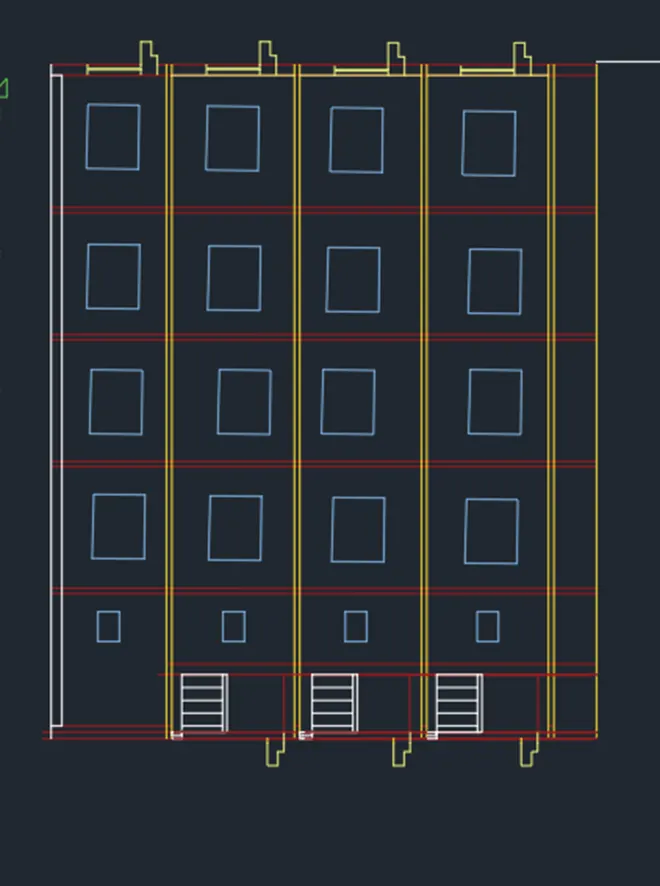
Result -
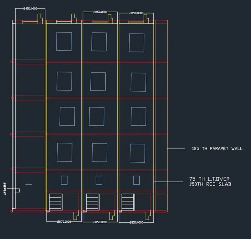
Final Drawing -