Creating a Layout, Section and Elevation with dimensions using AutoCad
CHALLENGE 7
AIM- TO DRAW PLAN ELEVATION AND SECTION OF THE HOUSE IN AUTO CAD.
INTRODUCTION
Commands used for drawing the plans and drawings below are as follows
- Line
- Polygon
- Rectangle
- Circle
- Ellipse
- Erase
- Copy
- Mirror
- Offset
- Extend
- Array
- Move
- Rotate
- Scale
- Trim
- Chamfer
- Fillet.
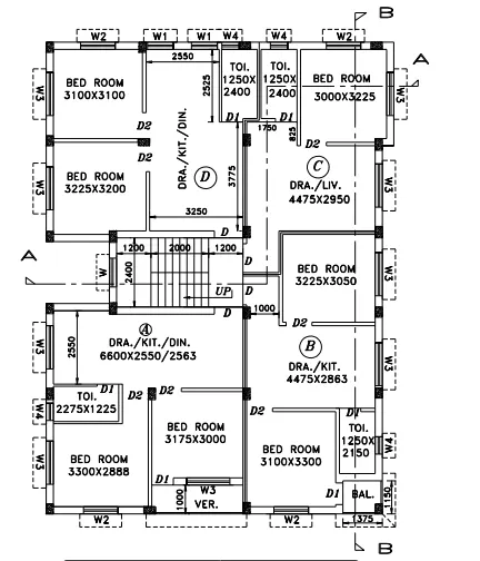
Now STEPS for drawing plan by using AUTO CAD
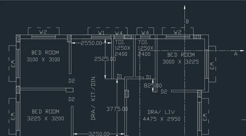
- Open auto Cad and enter UN (Units command) in the command box and select type as decimal and set precision of decimal as 0
- Select X line command and draw horizontal line and vertical line
- Trim the unwanted lines.
- Now select offset command and give an offset of 250mm to both horizontal and vertical line drawn by X line
- Give the offsets as follows in the X direction
- Offset 3100 for bedrom
- Offset 125 for internal wall
- Offset 2250 for kitchen/ drawing room / dining room
- Offset 125 for internal wall
- Offset 1250 for both toilet
- Offset 250 for external wall
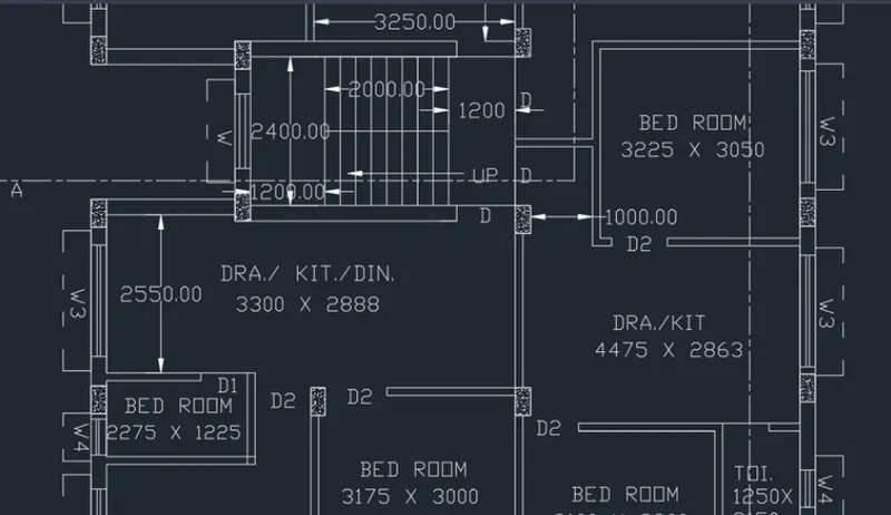
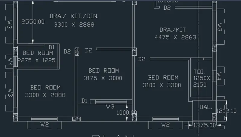
- Give the offsets as follows in the X direction
- Offset 3100 for bedroom
- Offset 125 for internal wall
- Offset 3225 for bedroom
- Offset 250 for wall on both sides of stars.
- Offset 250 for treads
- Offset 1200 for landing of staircase
- Offset 2400 for width of staircase
- Offset 2250 for kitchen dining bedroom
- Offset 1000 for veranda
DRAWING OF WINDOWS
W1= 1000 X 1200,W2= 1500 X 1200,W3= 1800X 1200,W4= 600 X 1050,W= 1200X 1200
DRAWING OF DOORS
D= 1200 X 2100, D1= 750 X 2100,D2= 900 X 2100
Windows are drawn by using line command
Section lines are drawing by using layer and changing the layer type.
Hatch- For hatching the columns type hatch in command box- open settings -select pattern- select pattern as AIR-CONC- select global scale factor as 0.8
Dimension- For drawing dimension using dimension tool in the ribbon
For naming of plan use text in ribbon in that use multiline text and keep the height of text as 220
RESULT
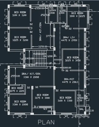
STEPS FOR DRAWING SECTION AA
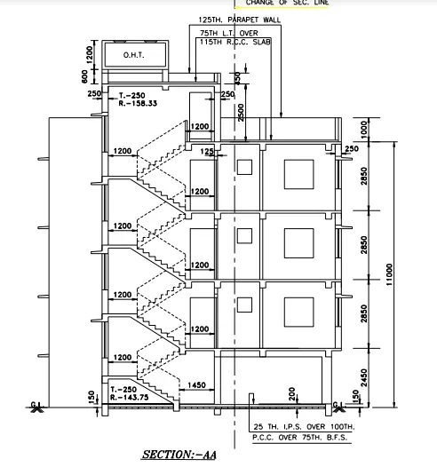
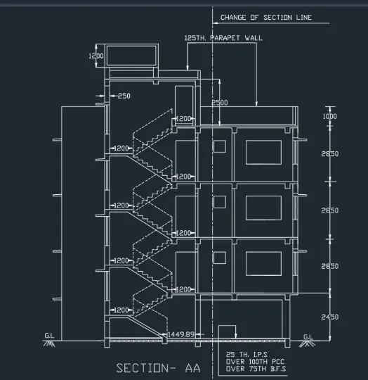
Select x line command and extend the lines from the plan in the downward manner to create projections
Offset 150mm from the ground level
Offset 2450 for ground floor
Offset 2850 for second floor
Offset 2850 for second floor
Offset 2850 for third floor
Offset 1000 for parapet wall
Offset 2500 from terrace level to mumty
Offset 450 from mumty for parapet wall of mumty
For drawing of staircase offset 1250 for thread and offset 143.75 for rise of staircase
Offset 125 below floor level for slab
Draw the chajjas and windows as per the sizes considered and standards
Draw the railing of staircase in dash manner from the layers and change the layer to ACADISO03W100
Give the dimensions by dim linear or dim continue command
Select the multiline text for naming of the section
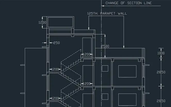
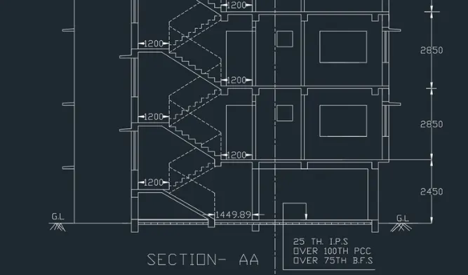
Final A-A Section
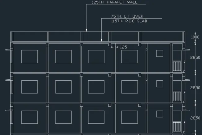
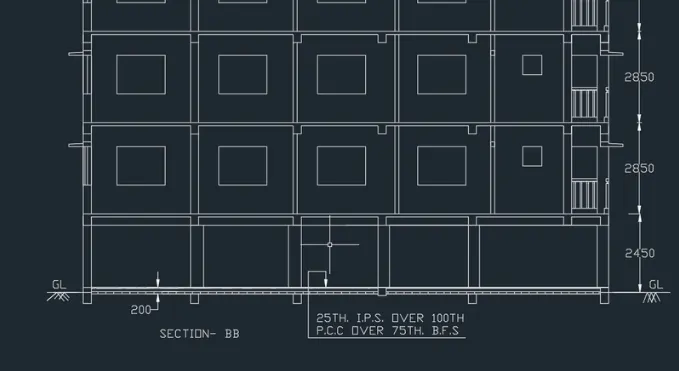
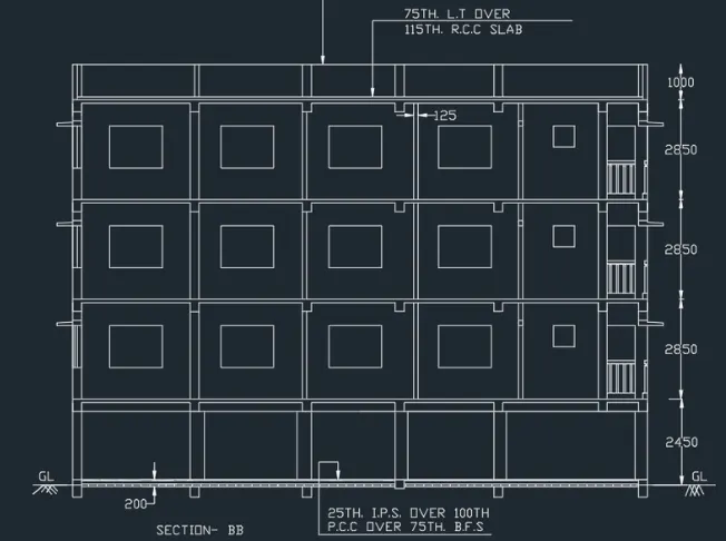
STEPS FOR DRAWING SECTION BB
- Rotate the entre plan drawn earlier in the 90 degrees direction draw the section BB
- Select x line command and take the projectors of the rotated plan in the downward manner
- Take the projections of all internal walls of 125 mm and eternal walls of 250mm
- Draw a base line to draw the section BB
- Offset 150 from base line
- Offset 2450 for ground floor
- Offset 2850 for first floor
- Offset 2850 for second floor
- Offset 2850 for third floor
- Offset 1000 for parapet wall
- Thickness of slab is assumed to be 125 mm
- Offset 125 rom each floor in downward manner
- And use dim linear or dim continuous for giving the dimensions