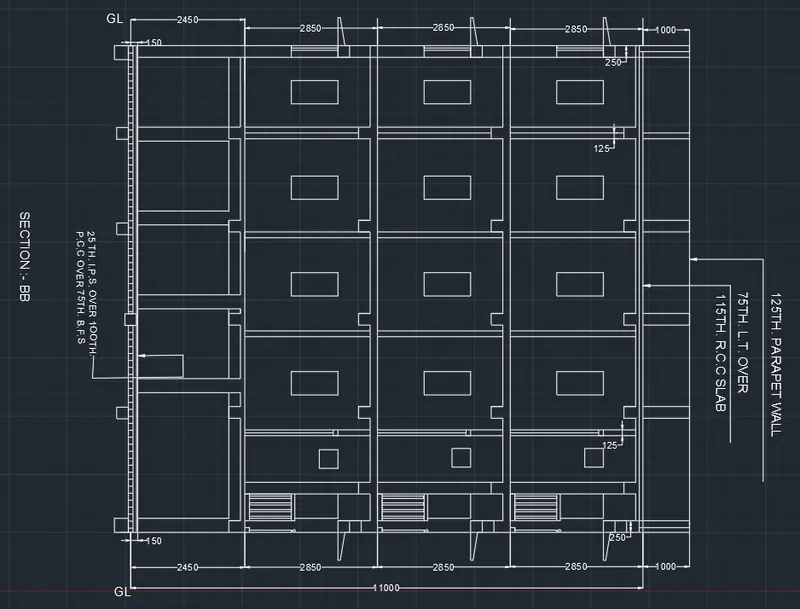
Creating a Layout, Section and Elevation with dimensions using AutoCad
Aim : To create a Layout, Section and Elevation with dimensions using AutoCad
Introduction :
- Open autocad application
- Type Qnew and open new drawing
- Set units according to drawing
- Switch on object snap and object snap modes : Endpoint, Midpoint, Center, Nearest, Intersection, Perpendicular and Node
- Ortho mode is ON
Problem 1 :
Aim : To create the plan and sections using AutoCad
Procedure :
- Set units to decimal, precision zero and units to scale as "mm"
- Procedure for dimensions setting : Enter command dimstyle
Click on new and create a new style "STYLE 1"
1. Now go to Lines section and set the following:
Color, linetype and lineweight remians "ByBlock"
Extend beyong dimlines as zero
Offset from origin as zero
2. Next go to symbols and arrow section and set the following:
Arrow size 30
3. Next go to Text and set the following:
Text style : Standard : Font style - Arial, Font name regular
Text color : Byblock
Text height : 100
Text placement both vertical and horizontal as centered, View direction as left to right
Offset from dimline : 1
Text aligment : Aligned with dimension
4. Next go to Fit and set the following:
Use overall scale of 1
5. Next go to Primary units and set the following:
Unit format : Decimal
Precision : 0
Press okay and click on set current
Press close - Draw a vertical line from origin of length 7243mm and draw another line parallel to it using offset at a distance 230mm
- From here draw a line by taking offset distance 3300mm, and then continue drawing lines at a distance 150mm, 3175mm, 150mm by taking offset from last drawn lines
- Draw a horizintal line from origin of length 7005mm and draw another line parallel to it using offset at a distance 230mm
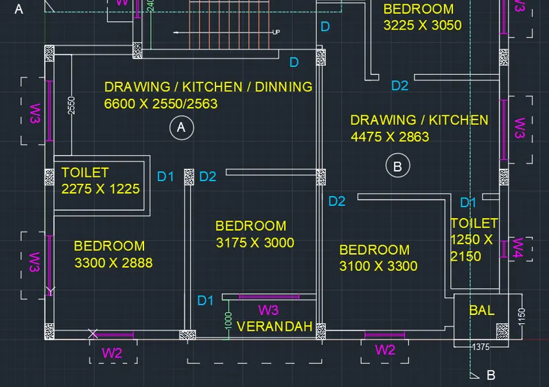
- Draw a horizontal wall of size 2375 x 230 mm at a distance 1000mm from bottom line and also draw 50mm thick line from bottom line (Trim off the extra line)
- From previous wall create another horizontal wall of size 2275 x 150 mm at a distance 3000mm as shown below
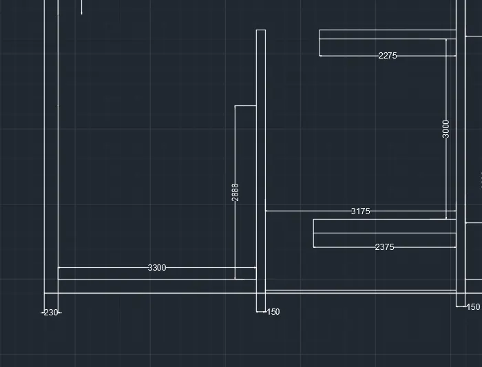
- Draw a room of size 2275 X 1225mm with wall thickness of 150mm as shown below
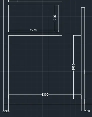
- Above this room create another room 6600 x 2550 mm (drawing room) with external wall thickness 230mm as shown below
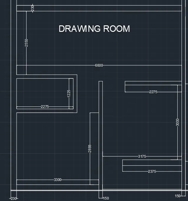
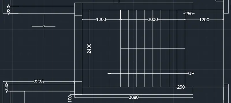
- Above this room create a staircase with tread as 250mm and beside the staircase draw a wall of thickness 230mm as shown below
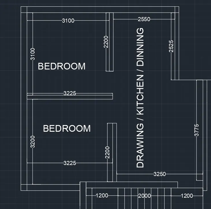
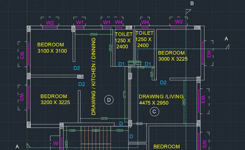
- Now draw two bedroom of sizes 3225 x 3200 and 3100 x 3100, and a drawing room as shown below with external wall thickness 230mm and internal wall thickness 150mm. Door opening is taken as 900mm
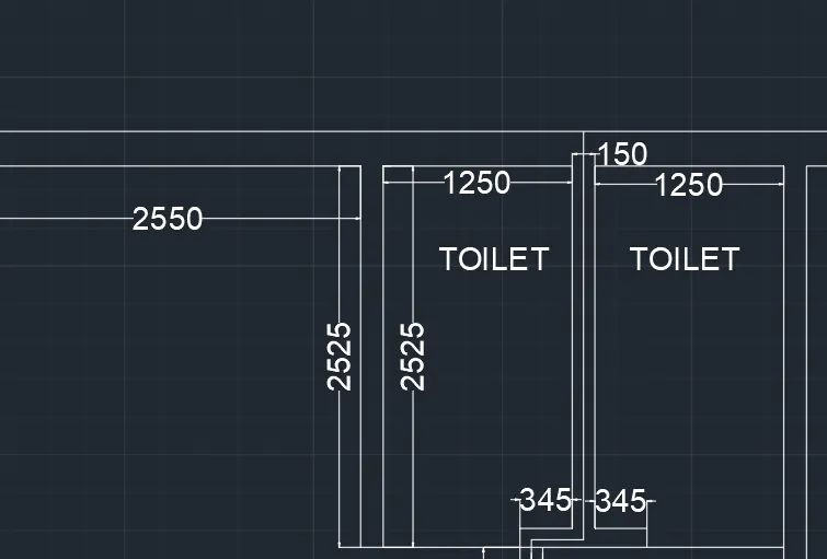
- Now beside drawing room create two toilets of size 1250 x 2400mm with wall thickness 150mm with door opening 900mm and draw a centralline for the common wall between two toilets as shown below
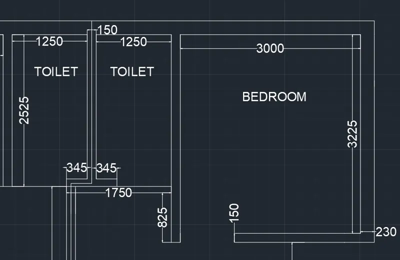
- Draw a bedroom of size 3000 x 3225mm beside toilets with external wall thickness 230mm, internal wall thickness 150mm and door opening 900mm as shown below
- Now draw another bedroom of size 3225 x 3050 from a distance 2950mm with external wall thickness 230mm, internal wall thickness 150mm and door opening 900mm as shown below
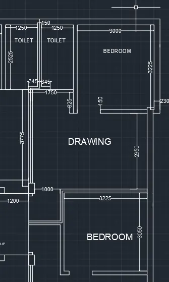
- As shown above column (230 x 400mm) is drawn near opening of staircase and 1000mm space is maintained in between
- A centralline is also drawn in of the internal walls as shown in figure.
- Now draw bedroom of size 3100 x 3300 and toilet of size 1250 x 2150 from a distance 2863mm with external wall thickness 230mm, internal wall thickness 150mm and door opening 900mm for bedroom and 800mm for toilet.
- Draw a balcony at right bottom corner of size 1375 x 1150 as shown below.
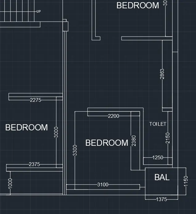
- Now draw foundations, windows as shown below
Foundation of size 230 x 400mm, Hatch the foundations using hatch pattern AR-SAND and scale 1
Window sizes W1 = 600mm
Window sizes W2 = 1000mm
Window sizes W3 = 1500mm
Window sizes W4 = 400mm
Window sizes W = 800mm 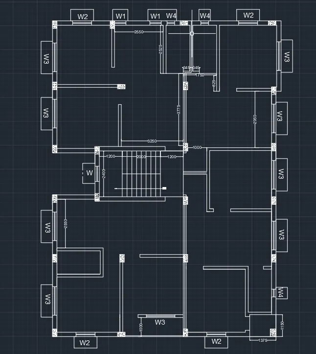
- Draw text in each room according to the given figure
Text height is taken as 250mm and text style as arial - Also draw text for doors D, D1 (800mm), D2(900mm)
- Draw sections "A" and "B" as shown below and take line type as center
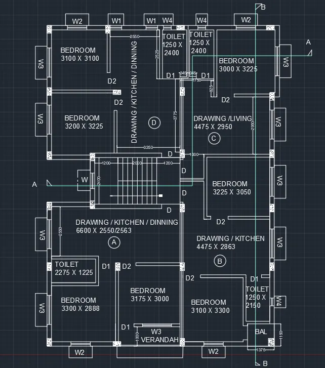
- Now create layers and assign it accordingly
Windows
Doors
Staircase
Text
Dimensions
Section (Linetype - Centre)
Layer 1 for the windows (ACAD_ISO03W100) - Mark the dimensions using dimlinear
Result :
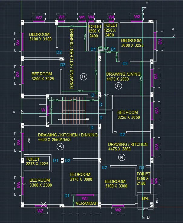
Problem 2 :
Aim : To create section AA of a building using AutoCad
Procedure :
- Set units to decimal, precision zero and units to scale as "mm"
- Procedure for dimensions setting : Enter command dimstyle
Click on new and create a new style "STYLE 1"
1. Now go to Lines section and set the following:
Color, linetype and lineweight remians "ByBlock"
Extend beyong dimlines as zero
Offset from origin as "3"
2. Next go to symbols and arrow section and set the following:
Arrow size 100
3. Next go to Text and set the following:
Text style : Standard : Font style - Arial, Font name regular
Text color : Byblock
Text height : 150
Text placement both vertical and horizontal as centered, View direction as left to right
Offset from dimline : 1
Text aligment : Horizontal
4. Next go to Fit and set the following:
Use overall scale of 1
5. Next go to Primary units and set the following:
Unit format : Decimal
Precision : 0.00
Press okay and click on set current
Press close - Draw a line representing "GL" and draw two lines offset to GL at a distance 25mm using XL command
- Now take any point on GL and draw a line vertically of length 14100 and draw another line parallel to it with offset distance 250mm
- Draw a column of size 250 x 2306.25mm at distance 4400 from the wall starting from GL
- Draw a horizontal line of length 4650 at a distance 150mm GL
- Draw a horizontal line of length 10000 from a distance 2450 GL
- From previous line draw 3 horizontal lines one above the other of length 10000 at a distance of 2850 each
- Now start the staircase at a distance 1450mm from the column and above 150mm thick line
- Rise of the staircase is taken as 143.75mm and tread as 250mm
- Upto 7 steps are drawn and connection landing (1200 x 100mm) to the wall at a distance 1200mm and draw stringer parallel to the staircase
- Now mirror the staircase towards up keeping the original copy also
- Draw two rectangles of size 250 x 750mm and 250 x 400mm as shown below
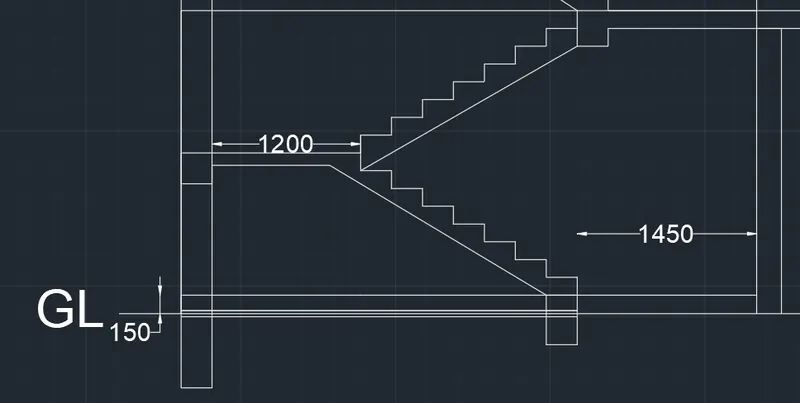
- Similarly draw the staircase at 1st floor, 2nd floor and 3rd floor with rise 158.33 and tread 250mm upto 8 steps
- Draw sunshades at mid landing of 1st floor, 2nd floor and 3rd floor using dimensions given below
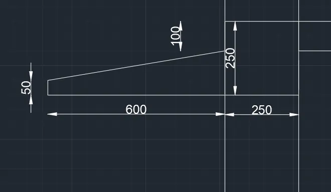
- Draw one more sunshade at a distance 1000mm from the top floor
- Draw windows below sunshade of size 250 x 1000mm
- Above groundfloor column, draw columns for 3 floors of thickness 125mm along with a centreline inside
- Draw doors of size 900 X 2440 in floor beside staircase at a distance 1200mm from the column
- Draw newel (height 900mm) and handrail for the staircase (Linetype : ACAD_ISO02W100)
- Draw a another column and projections in the 1st floor as shown below
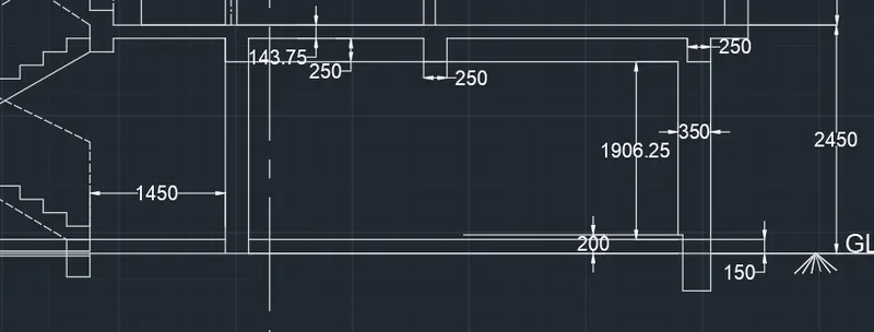
- Copy and paste these projections at top of 1st floor, 2nd floor and 3rd floor
- Now draw two columns in each floor, windows, sunshades as per given dimensions shown below
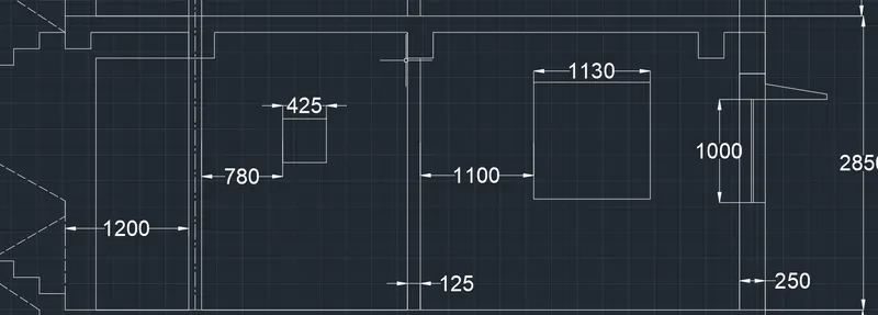
- Draw a section line (Linetype : DASHEDX2) taken from centre of diagram upto top of the diagram
- On the top floor draw a door (900 x 2300), column (250 X 2500mm) and other projections shown below
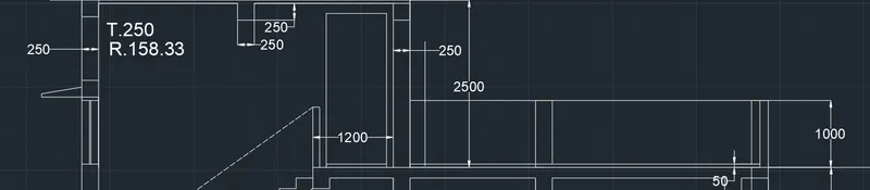
- Now draw over head tank of size 2575 x 1200mm above 600mm columns as shown below
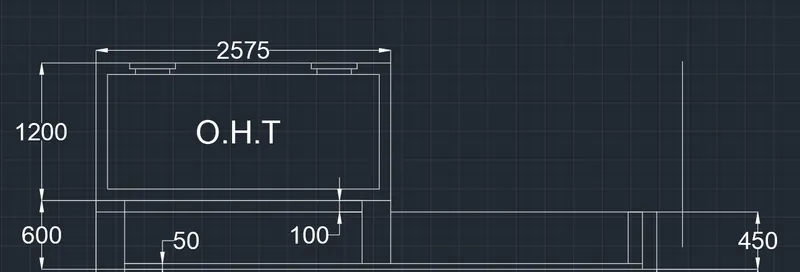
- Draw a vertical line 12000mm from GL towards up and continue to draw a horizontal line 1500mm which connects left side of the diagram
- Draw sunshades at left side aligning to each floor
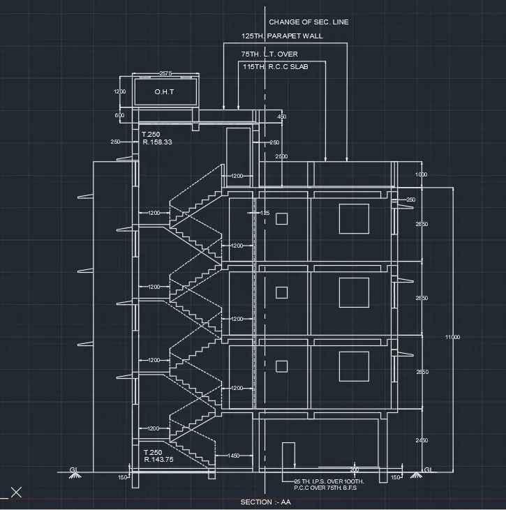
- Using leader draw (maximum leader point as 3) and write a text "25TH. I.P.S OVER 100TH P.C.C OVER 75TH. B.F.S at the GL (text height 150 and arrow height 150)
- Using leader draw (maximum leader point as 3) and write a text at top floor as (text height 150 and arrow height 150)
125TH PARAPET WALL
75TH LT OVER
115TH R.C.C SLAB - Mark the dimensions using dimlinear
Result:
Problem 3
Aim : To draw section BB using Autocad
Procedure :
- Set units to decimal, precision zero and units to scale as "mm"
- Procedure for dimensions setting : Enter command dimstyle
Click on new and create a new style "STYLE 1"
1. Now go to Lines section and set the following:
Color, linetype and lineweight remians "ByBlock"
Extend beyong dimlines as zero
Offset from origin as "3"
2. Next go to symbols and arrow section and set the following:
Arrow size 100
3. Next go to Text and set the following:
Text style : Standard : Font style - Arial, Font name regular
Text color : Byblock
Text height : 150
Text placement both vertical and horizontal as centered, View direction as left to right
Offset from dimline : 1
Text aligment : Horizontal
4. Next go to Fit and set the following:
Use overall scale of 1
5. Next go to Primary units and set the following:
Unit format : Decimal
Precision : 0.00
Press okay and click on set current
Press close - Draw a rectangle of size 12000 x 10250 using line tool
- Left side of rectangle is considered as GL
- Draw a offset on bothsides of GL at distance of 50mm and hatch this area
- From GL draw a vertical line by taking offset at a distance 150mm and from there draw another vertical line at a distance 25mm towards left
- Now draw 4 vertical lines
1. At a distance 2450 from GL
2. At a distance 2850 from 1st floor
3. At a distance 2850 from 2nd floor
4. At a distance 2850 from 3rd floor 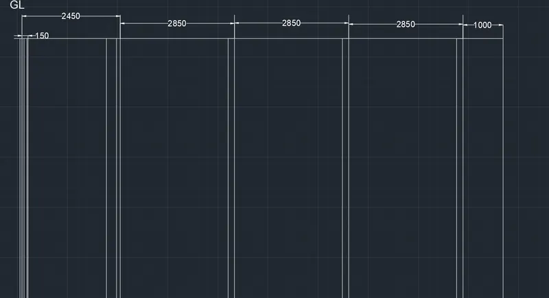
- Draw a vertical line by taking offset at a distance 2106.25 from GL and from this line draw another line by taking offset at a distance 250mm
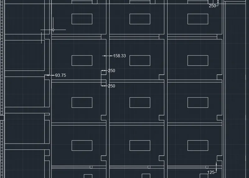
- Draw a vertical line by taking offset at a distance 93.75 from 1st floor towards left
- Draw a vertical line by taking offset at a distance 158.33 from second floor towards left
- Similary draw these lines by taking offset of 3rd floor and top floor
- Now draw a horizontal line by taking offset distance of 250mm from the rectangle at the top and bottom
- Draw a column of size 2300 x 300mm distance of 1500mm as shown below
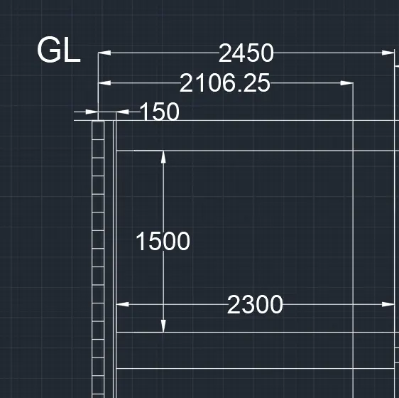
- Similarly draw 3 columns at a distance gap of 1500mm and last column i.e 4th column at a gap of 2700mm
- At 1st floor 2nd floor and 3rd floor draw one column (size 2441 x 125) each at a distance 1500mm and draw a center in each one of the columns
- Continue to draw next set of columns on each floor (1st, 2nd, 3rd floor) with thickness of 125mm at a distance 2000mm
- Last set of column is at a distance of 1000mm (1st, 2nd, 3rd floor)
- Now draw windows of size 1000 x 250mm on 1st, 2nd, and 3rd floor
- Draw sunshades above windows as per dimensions given below. These sunshades are drawn above and below of the rectangle (12000 x 10250)
- Now draw 5 rectangles in each floor
4 rectangles of size 1000 x 500 mm (from a distance 750mm from column) and last rectangle is of size 400 x 400 (from a distance 275mm from column) - At the bottom draw some part of staircase as shown below
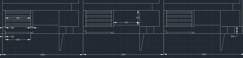
- Drawn projections of size 250 x 250mm at every 1750mm distance on a vertical line drawn by taking offset at a distance 93.75 from 1st floor towards left and a vertical line drawn by taking offset at a distance 158.33 from second floor towards left as shown below
- Draw columns at top floor of size 1000 x 250 mm
- Using leader draw (maximum leader point as 3) and write a text "25TH. I.P.S OVER 100TH P.C.C OVER 75TH. B.F.S at the GL (text height 150 and arrow height 150)
- Using leader draw (maximum leader point as 3) and write a text at top floor as (text height 150 and arrow height 150)
125TH PARAPET WALL
75TH LT OVER
115TH R.C.C SLAB - Write a text SECTION BB at bottom(font style arial and text height 150)
- Mark the dimensions using dimlinear
Result :