Creating a Layout, Section and Elevation with dimensions using AutoCad
1Q.
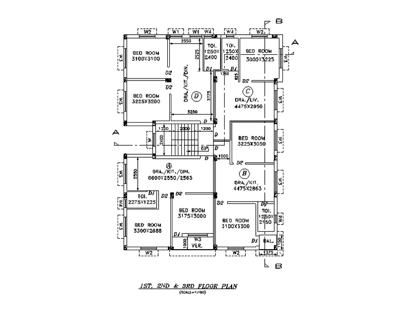
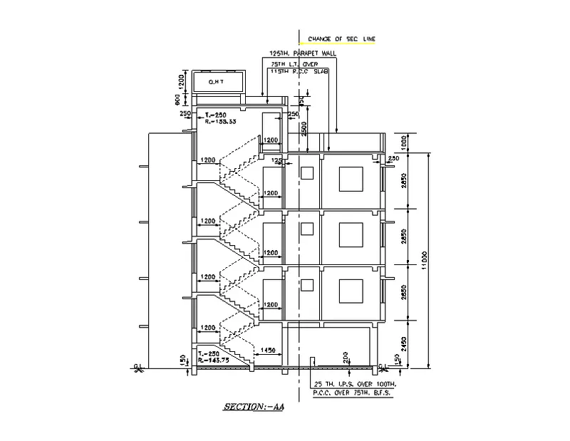
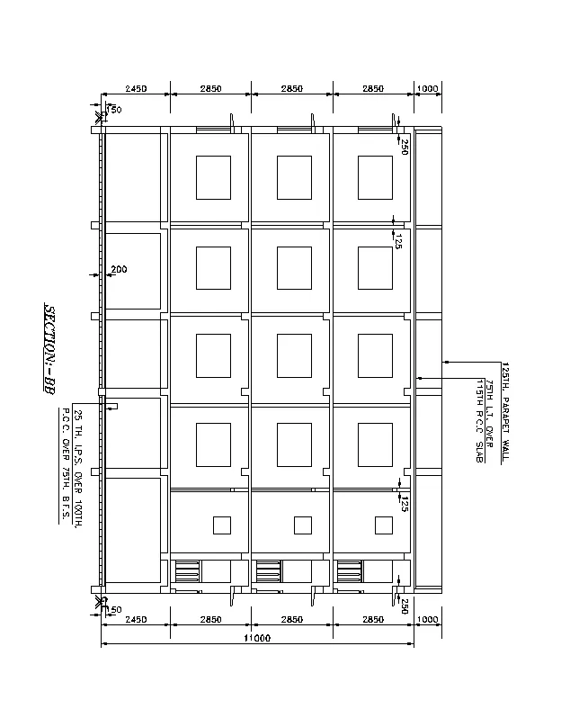
AIM:Create the Plan and Sections as shown in the Figures. Use proper dimension techniques and dimension styles to document the project. Assume the sizes of the doors and windows as per construction standards. Refer to sections for stair details if required.
PROCEDURE:
Type UN and press enter
Under Drawing Units, select decimal
Now the lower limit is set to 0, 0 and upper limit to 100000, 100000
Type Z enter to zoom and A enter to all
Using the construction line command XL horizontal and vertical lines was created.
Now by observing the plan by the OFFSET command draw the EXTERIOR WALLS of the drawing of 250 OF offset.
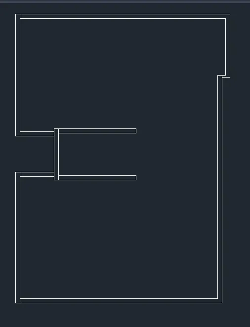
Now by using the OFFSET and TRIM commands create the INTERIOR WALLS of the plan and the thickness of the wall of interior wall is 125.
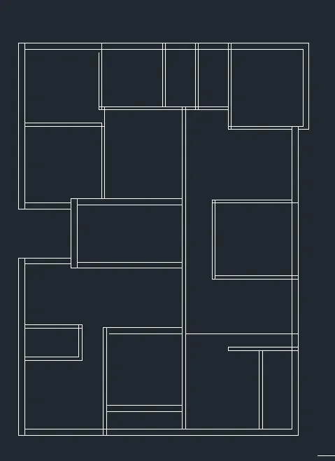
Now by using the RECTANGLE command draw the COLUMNS of the plan according to the plan.
The sizes of the columns are given 250x400.
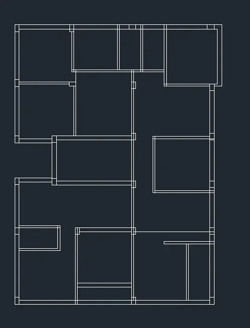
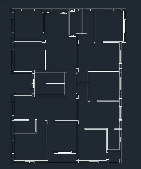
By using the TRIM command opening are drawn INTERIOR and EXTERIOR wall of the DOOR.
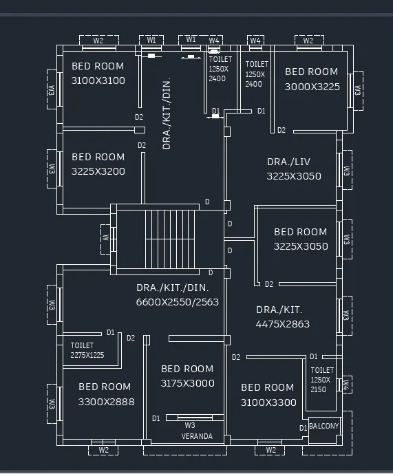
D1=700
D2=800
D=1000
BY using the OFFSET command draw the windows.
W1=800X600
W2=1000X1000
W3=1400X1200
W4=500X400
W=1000X1000
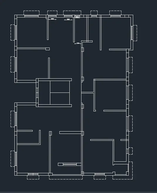
Draw the sunshades for the windos as 400 width and represent it in doted line selecting LINE STYLE MANAGER.
Now draw the STAIRS by using the LINE,OFFSET commands.
RAISE=250
TRADE=150
LANDING=1000
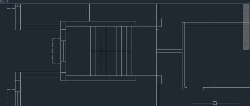
NOW add the the TEXT using MTEXT command and provide the necesssary information to the plan.
By using the DIMLIN command give the dimensions to the plan.
BY using the HATCH command hatch at the column.
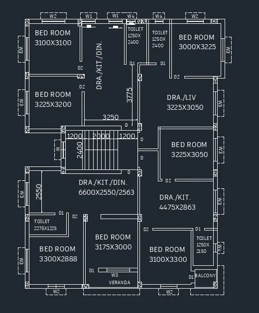
RESULT:PLAN LAYOUT IS COMPLETE.
SECTION BB
Now using the CONSTRUCTION LINE command XL and selecting the HORIZONTAL line draw the projection by taking the refernces to the columns.
By using the OFFSET command draw the INTERIOR WALLS and EXTERIOR WALLS of the section BB by observing the section BB take the SLAB thickness as 150.

Draw the windows of the SECTION BB by CONSRUTION LINE command HORIZONTAL to the windows projection.
By using the OFFSET command SILL level as 900 and LINTEL level 2100 set the offset and TRIM command trim the unwanted lines and by using the COPY command copy the remaining positons.
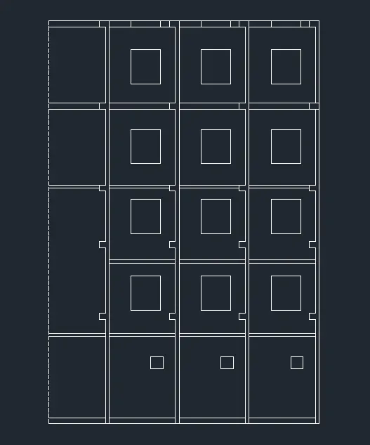
Now draft the BALCANY of the SECTION BB using LINE,OFFSET,TRIM command.
Also ground level as 200 and the PCC thickness 75 included.
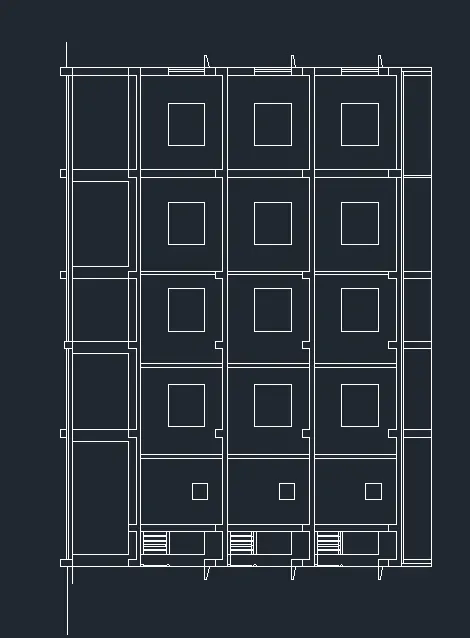
Now using MULTILEADER command text the given information in the SECTION BB.
BY using the DIMLIN and DIMCONT command draw the dimensions.
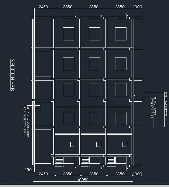
RESULT:SECTION BB LAYOUT IS COMPLETED.
SECTION AA
Now using the CONSTRUCTION LINE command XL and selecting the VERTICAL line draw the projection by taking the refernces to the columns.
By using the OFFSET command draw the INTERIOR WALLS and EXTERIOR WALLS of the section AA by observing the section AA.
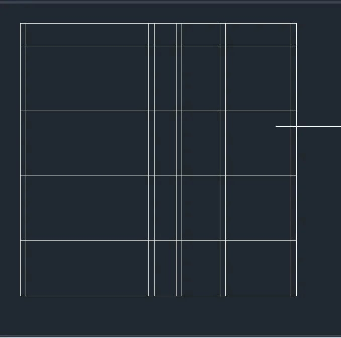
NOW draw the STAIRS of the SECTION AA
By using the LINE COMMAND
DIMENSIONS AS:FOR GROUNG FLOOR
RISE:143.75
TRADE:250
FROM 1ST FLOOR ALL
RISE:158.33
TRADE:250
LANDING:1200
Also ground level as 200 and the PCC thickness 75 included.

Draw the doors as 1000x2000 by using the LINE command.
Windows by using the CONSTRUCTION LINE XL vertical lines to the windows and SILL LEVEL AS 900 and LINTEL LEVEL 2100
by LINE, TRIM commands.
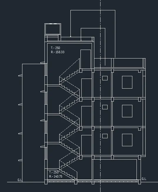
Now by using the DIMLIN and DIMCONT command give the dimensions of the SECTION AA
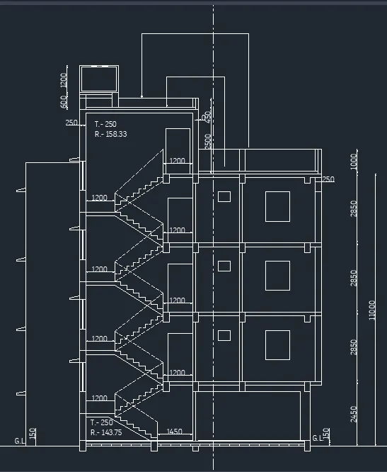
Give the TEXT by using the MTEXT,MULTILEADER commands and provide information as given below
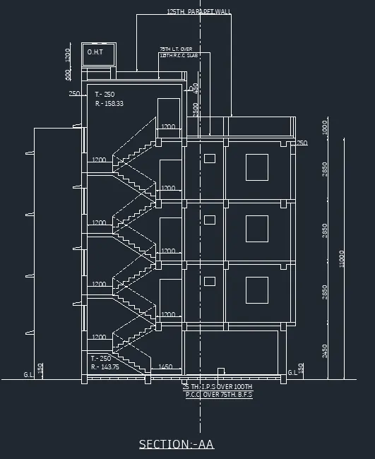
RESULT:SECTION AA layout is completed
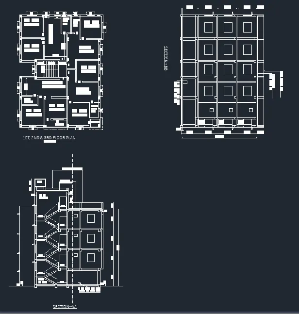
RESULT: LAYOUT OF THE 1ST,2ND &3RD FLOOR PLAN and SECTION AT BB and SECTION AT AA is commpleted.