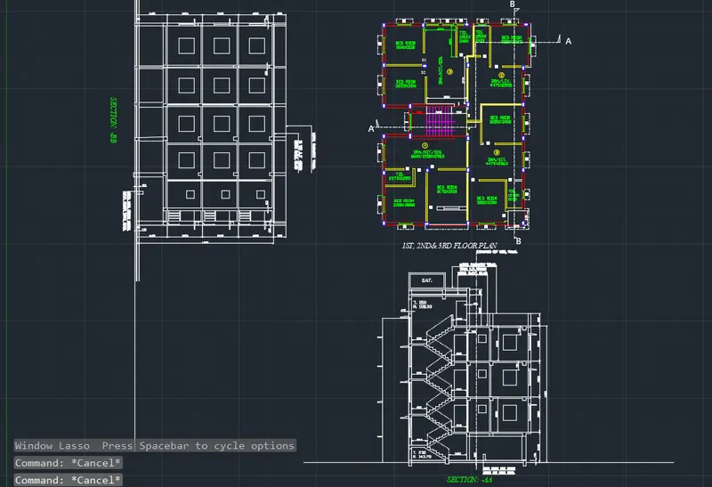
Creating a Layout, Section and Elevation with dimensions using AutoCad
QUESTION NO. -1 :
Create the Plan and Sections as shown in the Figures. Use proper dimension techniques and dimension styles to document the project. Assume the sizes of the doors and windows as per construction standards. Refer to sections for stair details if required.
ANSWER:
AIM : -Create the Plan and Sections as shown in the Figures. Use proper dimension techniques and dimension styles to document the project. Assume the sizes of the doors and windows as per construction standards. Refer to sections for stair details if required.
INTRODUCTION : - In this question we have to draw a plan and section with proper dimention style. in this drawing we use the dimecontinue command for continue the dimention. with same we use base line dimention to start the dimention with base point of the building .we have to use Mtext command for write the text content , we use the diffrent text style and Text sizes according to drawing. we have to use multileader and finally use layer command to work with particular layer. give line type , line weight and color of the line or any object for better understanding.
Autocad Drawing File Link:-
https://web.autocad.com/acad/me/sid/shares/drawings/abd7da34-4757-447d-8881-4c600ce9a2e4/editor
https://web.autocad.com/acad/me/sid/shares/drawings/abd7da34-4757-447d-8881-4c600ce9a2e4/editor
PROCEDURES:-
FOR START THIS DRAWING FIRST OF ALL WE HAVE TO DO SOME SETTINGS ACCORDING THE DRAWING -
SETTINGS - OPEN AUTOCAD
- SET DEFAULT SETTINGS - METRIC [MM]
- SELECT A TEMPLATE - ACCORDING TO DRAWINGS
- SELECT A WIZAED - ADVANCED SETUP
- UNITS - DECIMAL, PRECISION -0
- ANGLE - DECIMAL DEGREES
- ANGLE MEASURE - ACCORDING TO PLAN
- ANGLE DIRECTION - COUNTER CLOCKWISE
- ARE - ACCORDING TO PLAN
After this enter "D" for dimetion unit and set primary unit DECIMAL set precision 0
MODES -
- GRID ON BY F7 'CONTROL+G'
- USE ORTHO MODE FOR STRAIGHT 90 DEGREE ACCRDING NEED(F8)
- ON POLAR TRACKING (F10) SET ANGLE (15,30,45)
- OBJET SNAP TRACKING (F11)
- OBJECT SNAP (F3)
- TRANPARANCY ON WHEN YOU NEED
SOME OTHER DATA [ASSUMED]
- OUTER WALL THICKNSS - 230mm
- INTERNAL WALL THICKNESS 115mm
- DI DOOR - WIDTH 1220mm [3']
- D2 DOOR - WIDTH 762mm [2'6"]
- D3 DOOR - WIDTH 990mm [3'-3"]
- HEIGHT OF ALL DOOR 2032mm [6''8"]
TO DRAW THE LAYOUT PLAN WE FOLLOW THE FOLLOWING STEPS : -
STEP -1
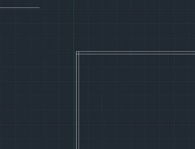
- Take construction line by enter command XL or from ribbon.
- Put it vertically and horizontally according to step one drawings.
- Take offset 230mm for give the exterior wall thickness vertically and horizontally.
STEP -2
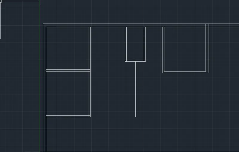
BEDROOM (UPPER SIDE IN PLAN):
- with the help of line comamnd draw the bedroom of 3100x3100 from the corner of the line for this take offset of 3100mm from vertical line and 3100 from horizontal line .
- Provide the intarnal wall thickness 115 mm bottom and Right side if bedroom.
- Draw second bedroom of 3225x 3200 . to draw this take offset 3225 from upper to downward and offset 3200 from vertical line .
- Provide internal wall thiickness 115mm.
STEP -3
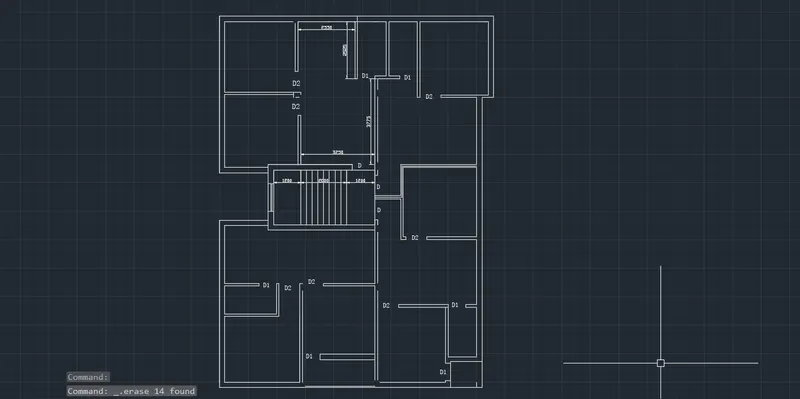
STAIRE PORTION:
- To draw the staire of the the plan take offset 2400 for HORIZONTALLY of stair.
- Take Landing 1200 from outer wall and put thread 250 mm .
- leave Open space for D -door.
STEP -4
BEDROOMS & TOILET
- Draw the Drawing/kitchen/dining room with dimention is 6600x2550x2563
- take offset 2275 horizontally for downward toilet and provide 115 mm wall thickness
- Again draw bedroom 3300x2888 bellow side of the toilet. and provide 115 mm wall thickness.
- draw bedroom 3175x3000 right side of the bedroom and provide 115 mm wall thickness
- bOTTOM side of this room Draw 3000 x 1000 veranda. and upper side draw room of 3175 x3000.
STEP -5
DOOR :
- Now we start putting the door in the wall
- So before putting the doors we have to know the sizes of the door . we assuming the difrent type of door for this plan.
DOOR -D - 990MM [WIDTH]
DOOR - D1- 761MM [WIDTH]
DOOR - D2 - 915 [WIDTH]- Toilet door :- D1 (d1 provide in the tiolet portion )
- Bedroom Door:- D2 (d2 door provide in the bedroom)
- Other door:- D (this door is Provide fron of stair)
- Putting the door Size using line trim and extend command
STEP -6
DIMENTION & TEST :-
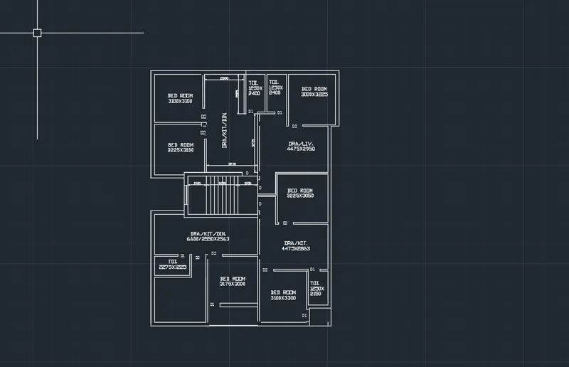
- After this we will text The dimention and name of the object.
- Before this Press 'D' enter set the new dimention style , dimention formate , text style and height of the text.
- After setting the size start the writing part from corner bedroom.
- write Text content and below Size of the room (width X lenght formate).
STEP -7
WINDOW:
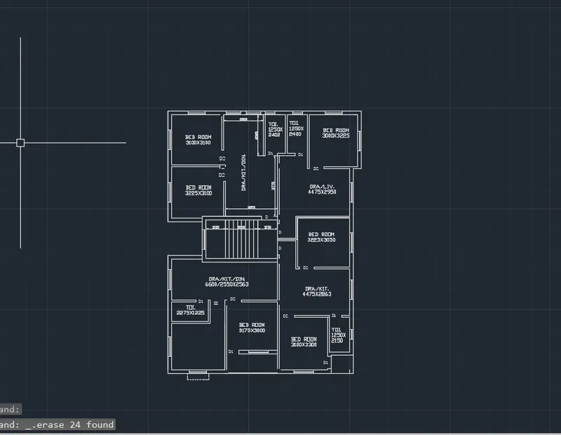
- Now will start draw the window and Put it on the outer wall of the building.
- draw manually window of diffrent sizes and Start putting with center point of the line.
- Diffrent window of this Plan Assumed by me is below.
WINDOW - W - 1370MM [WIDTH]
WINDOW - W1 - 915MM[WIDTH]
WINDOW - W2 - 1065[WIDTH]
WINDOW - W 3 - 1220[WIDTH]
WINDOW - W4 - 610 [WIDTH] - This is the diffrent types of window which is required in this plan
STEP -8
COLUMN:
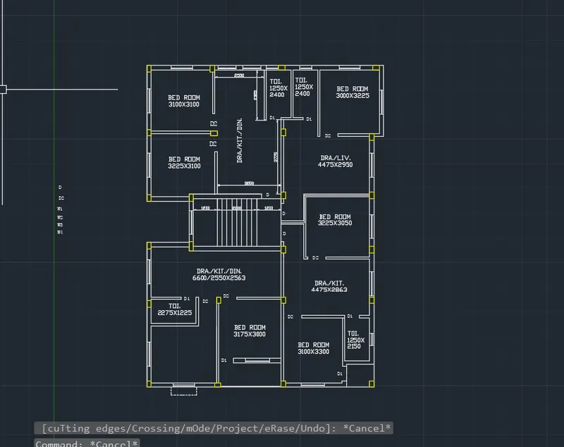
- Go to Layer Properties make new Layer and Column and give line type line weight and color .
- After This we will start putting the column of the plan.With column layer
- For the column draw it with the help of REC command and Just copy it and paste it for the corner points
- according to the plan put all the column with X direction and Y direction.
STEP -9
CHAJJA
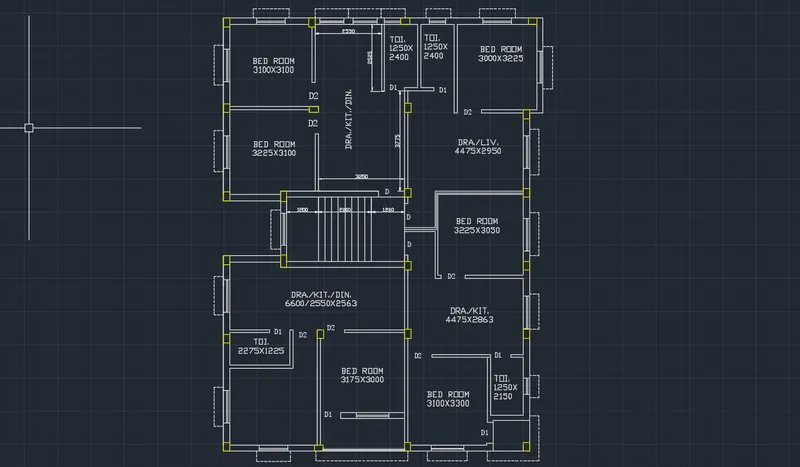
- Now we start drawing of chajja of the windows.
- For Chajja of the window go to layer Properties an make new layer 'Chajja'
- Set Line Type- Center line, Line color , And Line weight of the line .
- Than start Drawing to draw the chajjar.
- Take Width of the chajja is 75mm to 115 and lenght 450mm.
- and Draw with CHajja layer.
STEP -10
SECTION AA'
- GO TO LAYER PROPERTIES AND MAKE NEW LAYER OF SECTION AND SET LINE TYPER AND LINE WEIGHT .
- WITH THE HELP OF SECTION LAYER DRAW THE SECTION OF AA'
- AND AFTER AA' SECTION DRAW SECTION BB' WITH THE HELP OF LINE COMMAND.
- AFTER THIS PUT THE NAKE OF WINDOW W,W1 ,W2,W3,W4
- PUT ABCD MARK ON THE PAN
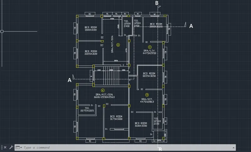
STEP -11
- Finally the Drawing is almost complete in the last stage go to layer Properties and make new layer for Ex-wall , In-wall ,
- give line type , line weight and color of the line.
- Give the title of the
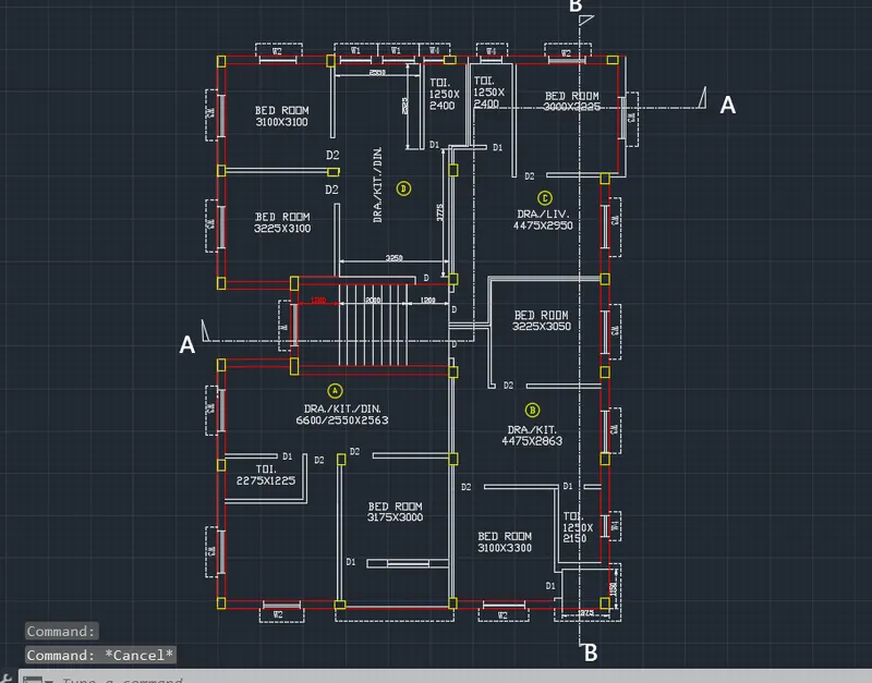
STEP -12
- Use Text command to give the plan details with use of Proper dimention style
- Use Center line formate to draw SECTION :-AA' and SECTION BB'
- With the help of trim or erase command trim the all unwanted lines .
- With the Help of Dimention command show all the dimention and after one time dimention take dimcontious for continue the next dimention.
- USE dim-continue for
- give heading of the plan
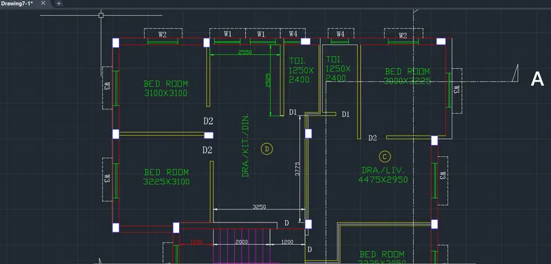
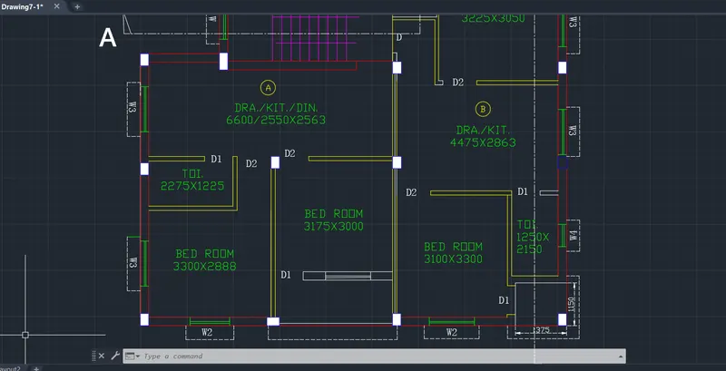
STEP -13
One Page Drawing formate
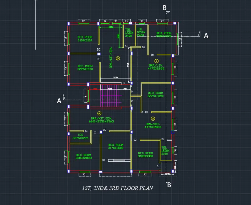
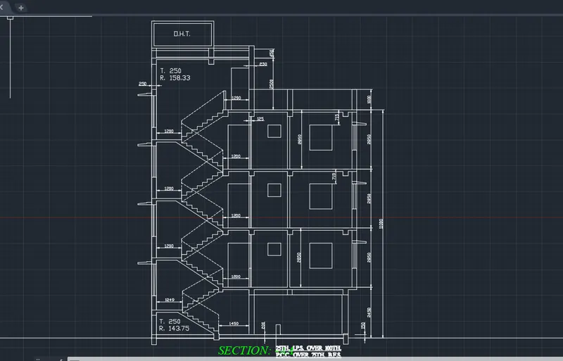
SECTION :AA AFTER COMPLETED THE PLAN WE WILL START TO DRAWING THE SECTION AA' PART OF THE GIVEN DRAWING.
TO DRAW THE LAYOUT PLAN WE FOLLOW THE FOLLOWING STEPS : -
STEP:-1
- Take Construction line and Put it Horizontally below the building plan
- Set the Area according to 3 story of the building.
- Start putting the Pojection of the Plan to the Horizontal line. with the help of Construction line(XL)
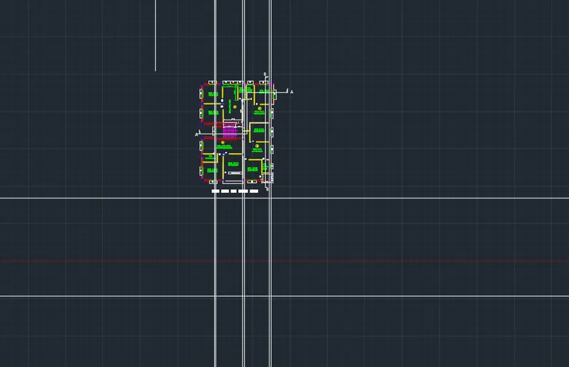
STEP -2
- Width the help of of XL command Put Projection line vertically .
- take it from corner of the building , corner of the window and corner of the wall according to SECTION AA'
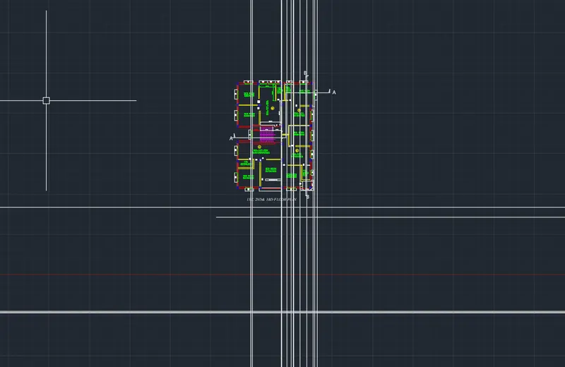
STEP -3
- After Taking Projection use Trim Command for erace the unwanted line.
- Take GK 200mm and 150 mm with the help of offset command.
- take offset command take window height 915mm from first floor
- Give 115 mm slab thickness
- After this Use trim Coomand and trim the line outside of the window .
- Wind
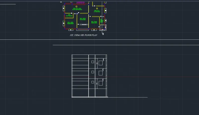
STEP -4
- Now we start making stair of the plan.
- Take stair Projection with help of XL Command.
- For Ground Floor Stair Take 250mm Thred and 143.75mm riser
- Start it making with Stair Projection Line.
- Draw stair starting to the landing. and for above stair Select this stair and with use off Mirror Command Mirror it From upward Direction.
- Again Select it and put it above 143.75 two times.
- Draw the landing With line Coomand distance of 1200 from outer wall
- For First Floor secont , and third Stair Take 250mm Thred and 158.33mm riser
- Start it making with Stair Projection Line.
- Draw stair starting to the landing. and for above stair Select this stair and with use off Mirror Command Mirror it From upward Direction.
- Again Select it and put it above 158.33 two times.
- Draw the landing With line Coomand distance of 1200 from outer wall
- Use Trim Command to Trim the all unwanted line . and Extend command if need to extend the line
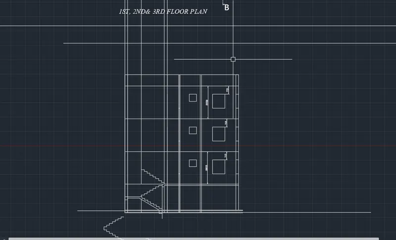
STEP -5
- With the help of Projection Line Draw the chajja of the SECTION AA"
- Draw the upper Most Part of THe Building (D.H.T.) with the help of osset and line command.
- Put The window Both Side Of the Plan. from first to third floor.
- Draw Parapet wall 1000 mm
- Draw the Doors for upper part take offset 450 mm again tak 600 mm take wall 125 mm and the the D.H.T. Part.
- Go To Dimention Command and Text
- After this we will text The dimention and name of the object.
- Before this Press 'D' enter set the new dimention style , dimention formate , text style and height of the text.
- After setting the size start the writing part .
- write Text content and below Size of the room (width X lenght formate).
- Use Dim-Continue For Continue THe Dimention.
- Go TO Leader And make New,
- Set size of Arrow , Text height Text style And No . Of segment 4 For Write the Data.
- Text All THe Text Content And
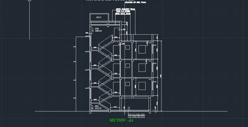
SECTION :BB'
AFTER COMPLETED THE PLAN WE WILL START TO DRAWING THE SECTION BB'' PART OF THE GIVEN DRAWING.
TO DRAW THE SECTION PLAN WE FOLLOW THE FOLLOWING STEPS : -
STEP:-1
- Take Construction line and Put it VERTICALLLY LEFTSIDE OF the building plan .
- Set the Area according to 3 story of the building.
- Start putting the Pojection of the Plan to the VERTICAL line. with the help of Construction line(XL)
- Firstly putting the outer wall Projection then Window Projection Line.
- Use trim Command And trim unwanted Line And Select Lines For Delete.
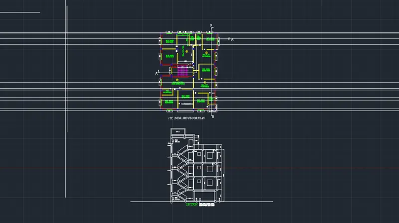
STEP:-2
- Use Trim Command To Erase The internal Unwanted Lines of the floor
- trim lines After triming Projection Lines Deleted after selecting
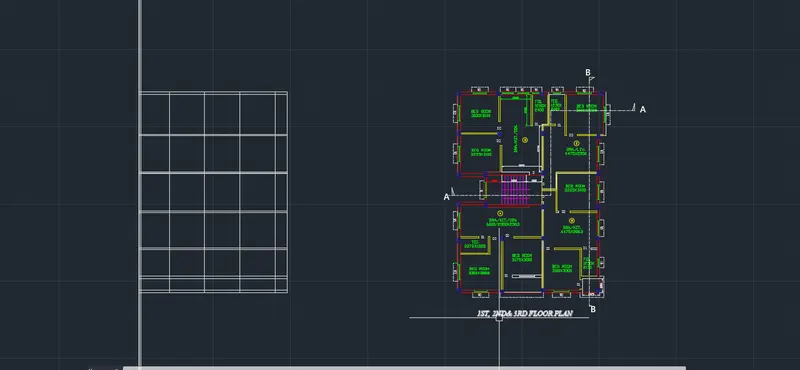
STEP:-3
- Put again remaining projection lines use of Construction Line Command .
- Again Trim with the help of Trim Command.
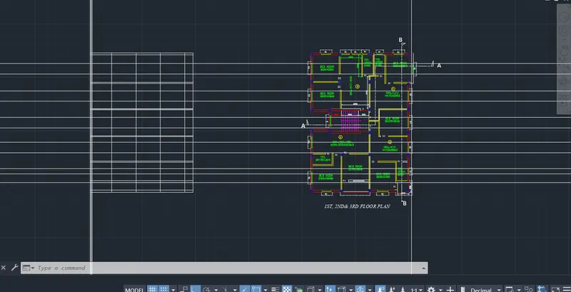
STEP:-4
- with the Help Of Trim Command Trim outer are of the window and trim unwanted lines.
- make Column Shape Of the Plan
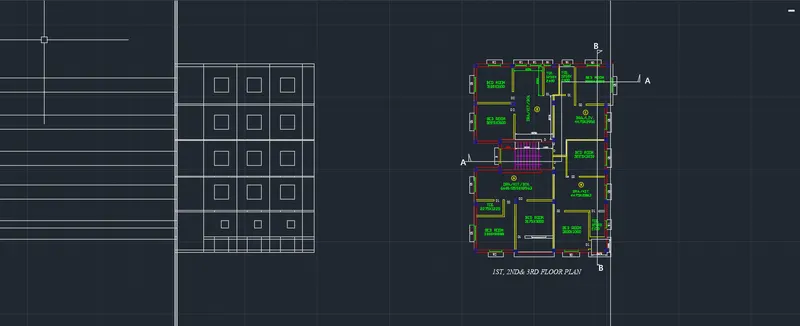
STEP:-5
- according To the given Plan Draw the systematically all wall Column and elevation part
- Go to dimention tool and show the dimention floor to floor.
- For above dimention go to Dim-continue for Continiue the dimention .
- Go to Leader And Use The leader to show the text Content accoring to requiremet.
- before use leader set setting like Arrow size , Text Style, Segemnt POint etc.
- Provide the Drawing name SECTION BB'
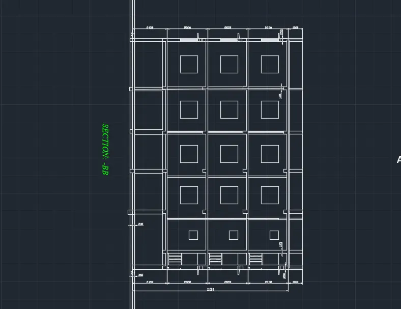
STEP:-6
- Use Qleader command to show the text .
- and use text content
- show all the dimention with dim-continue.
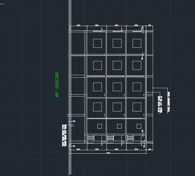
RESULT :-
ALL THE GIVEN PLAN AND SECTIONS DRAWINGS COMPLETED WITH THE PROPER DIMENTION TECHNIQUES DIMENTION STYLEE .AFTER MAKING THE DRAWING FINAL DRAWING SCREENSHOTS ARE ATTACHED WITH RESULTENT DRAWING .THE LINK OF THE DRAWING OF AUTOCAD IS ALSO ATTACHED FOR REFRENCE.
RESULTANT DRAWING:
DRAWING NO.1
DRAWING NO.2
DRAWING NO.3
FINAL PROJECT DRAWING
Autocad File Link:-
https://web.autocad.com/acad/me/sid/shares/drawings/abd7da34-4757-447d-8881-4c600ce9a2e4/editor
https://web.autocad.com/acad/me/sid/shares/drawings/abd7da34-4757-447d-8881-4c600ce9a2e4/editor