Creating a Layout, Section and Elevation with dimensions using AutoCad
Aim:
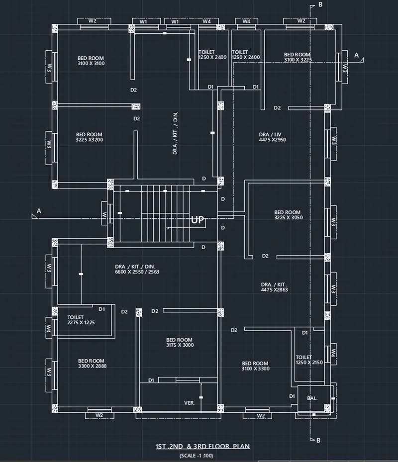
To create the Plan and Sections as shown in the Figures
Introduction :
Various command used while Sketching :
- Line command
- Unit command
- Lim max command
- XL command
- Zoom command
- Arc command
- Trim command
- Text command
- Extent command
- Fillet command
- Rectangle command
- Circle command
- Copy command
- LT command
- Dimension command
- Layer command
- Offset command
- Limits command
PRODUCTRE :
STEP 1 :
- GO to START MENU ,select AutoCAD 2018.
- Enter “UNITS” command in the command tab.
- Open “ Drawing units “ dialogue box , Type as “Decimal ” and precision as 00
- Then click units scale to “ millimetres ”
- Click “OK”.
- Enter “ LIM MAX” command in the command tab.
- Enter new value for Lim max as 20000’.
- Enter “zoom” command in the command box.
- Enter “All” command in the command box.
- Enter “LIMITS” command in the command box.
- Specify lower left corner as
- Enter “zoom “ command in the command box.
- Enter “ALL” command in the command box.
Step 2:
CREATING FLOOR PLAN :
- Enter “XL “ (OR) “ X line” command in the command box.
- Specific a point as “Vertical” command in the command box.
- Move the line to somewhere , where you want
- Than click “ESC” command in the command box.
- Enter “XL “ (OR) “ X line” command in the command box.
- Specific a point as “Horizontal” command in the command box.
- Move the horizontal line to close to the vertical line.
- Than click “ESC” command in the command box.
- First create plan as per the drawing
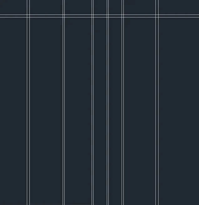
- Enter “OFFSET” command in the command box .
- Give a value of “250mm “ of wall thickness horizontally and vertically .
- Then we create a Bedroom, Toilets
- Enter “OFFSET” command in the command box .
- Give a value of “3100mm” from the right side wall .
- Enter “OFFSET” command in the command box .
- Give a value of “150mm” from the previse line between bed room in right side .
- Enter “OFFSET” command in the command box .
- Give a value of “2550mm” from the bed room wall of “150mm”
- Enter “OFFSET” command in the command box .
- Give a value of “150mm” from the previse line between TOILET AND BED ROOM in right side .
- Enter “OFFSET” command in the command box .
- Give a value of “1250mm” from the privies wall of “150mm”
- Enter “OFFSET” command in the command box .
- Give a value of “150mm” between the first toilet.
- Enter “OFFSET” command in the command box .
- Give a value of “1250mm” from the privies wall of “150mm”
- Give a value of “150mm” between the 2nd
- Enter “OFFSET” command in the command box .
- Give a value of “3000mm” from the toilet wall of “150mm”
- Enter “OFFSET” command in the command box .
- Give a value of “250mm” from the Previous line.
- Enter “TRIM” command in the command box.
- Trimmed unwanted line in the drawing.
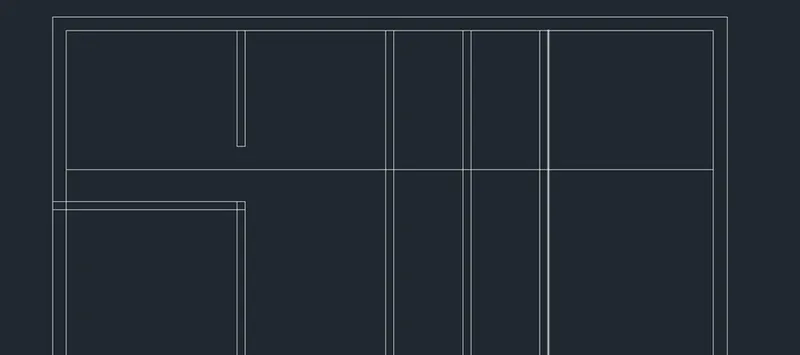
- Enter “OFFSET” command in the command box .
- From the horizontal wall to give a value of “3100mm”
- Create a line asper the drawing .
- Enter “OFFSET” command in the command box .
- Give a value of “ 150mm” from the previous horizontal line for internal wall thickness .
- Enter “OFFSET” command in the command box .
- Give a value of “2525mm” from the top wall to toilet horizontal line asper the drawing
- Then will create a Bedroom horizontal line ,
- Enter “OFFSET” command in the command box .
- Give a value of “3225mm” from top of the external wall in the left side bedroom
- Enter “OFFSET” command in the command box .
- Give a value of “150mm” from the previous line.
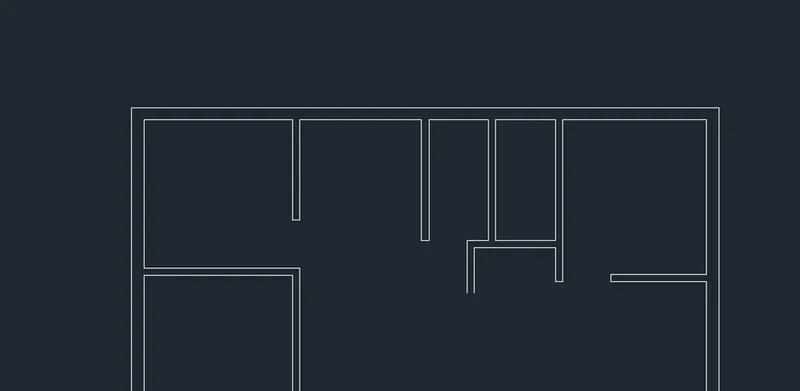
- Enter “OFFSET” command in command box.
- Give a value of “3200mm” in horizontally ,
- Enter “OFFSET” command in the command box .
- Give a value of “250mm” wall thickness from the previous line.
- Enter “OFFSET” command in the command box .
- Form the left side external wall to internal wall between the bedroom give a value of “3225mm”
- Enter “OFFSET” command in the command box .
- Give a value of “150mm” from the previous line.
- Now will create / KIT./ DIN./ in the top side.
- Enter “OFFSET” command in the command box
- Give a value of “3250mm” from the previous internal wall.
- Enter “OFFSET” command in the command box .
- Give a value of “150mm” from the previous line.
- From the toilet door to stairs give a length of “3775mm”
- Enter “OFFSET” command in the command box .
- From the / KIT./ DIN./ wall to DAR./ LIVE/ distance as give a value of “4475mm” in the vertical line
- Enter “OFFSET” command in the command box .
- Give a value of “250mm” from the previous line
- Enter “TRIM” command in the command box.
- Trimmed unwanted line in the drawing.
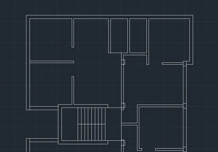
- NOW we will create stair case.
- Enter “OFFSET” command in the command box.
- Give a value of “1200mm” from the left side external wall.
- Then give a value of “2000mm” and 1200mm” vertically
- Enter “OFFSET” command in the command box.
- Give a value of “2400mm” horizontally
- Enter “OFFSET” command in the command box.
- Give a value of “1000mm” from the stairs case
- Enter “OFFSET” command in the command box.
- Give a value of “150mm” for the wall thickness from
- Enter “OFFSET” command in the command box.
- Give a value of “3225mm” from the wall thickness of “150mm” vertically
- Enter “OFFSET” command in the command box.
- Give a value of “250mm” for external wall.
- Enter “OFFSET” command in the command box.
- give a value “3050mm” from the /LIV./
- then create wall thickness of “150mm” horizontally
- Enter “TRIM” command in the command box.
- Trimmed unwanted line ,create drawing as per the model
- now will start draw / KIT./DIN./
- Enter “OFFSET” command in the command box.
- Give a value of “2550mm” from the stairs wall horizontally
- From the left external wall to between / KIT./DIN. Give a value of “6600mm” vertically
- Enter “OFFSET” command in the command box.
- give a value of “1225mm” from the wall of “DRA./KIT./ DIN. In downside.
- From the left side external wall give a value of “2275mm”
- Enter “OFFSET” command in the command box.
- give a value of “150mm” wall thickness for internal wall.
- Enter “OFFSET” command in the command box.
- Give a value of “2888mm” from the toilet .
- Enter “OFFSET” command in the command box.
- Give a value of “250mm” for external wall extremally.
- Enter “OFFSET” command in the command box.
- Give a value of “1000mm” form down external wall For
- Enter “OFFSET” command in the command box.
- Give a value of “3000mm” from the VER. Horizontally in top side .
- Enter “OFFSET” command in the command box.
- Give a value of “150mm” from the privies line
- Enter “OFFSET” command in the command box.
- Give a value of “3100mm” from the center bedroom
- And also give a value of “150mm” for the wall thickness
- Enter “REC” command in the command box.
- give a value of “1150 X137mm” in corner of right side down
- Enter “OFFSET” command in the command box.
- Give a value of “250mm” from the balcony .
- Enter “OFFSET” command in the command box.
- Give a value of “2150mm” for toilet.
- Enter “OFFSET” command in the command box.
- from the right wall give a value of “1250mm”
- Enter “OFFSET” command in the command box.
- Give a value of “150mm” for wall thickness of Toilet
- Enter “OFFSET” command in the command box.
- Give a value of “2863mm” from the downside bedroom.
- Enter “OFFSET” command in the command box.
- Give a value of “3050mm” from the / KIT.
- Enter “OFFSET” command in the command box.
- Give a value of “150mm” for the wall thickness.
- Enter “OFFSET” command in the command box.
- Give a value of “3225mm” from the external wall
- And also give a value of “150mm” for the wall thickness
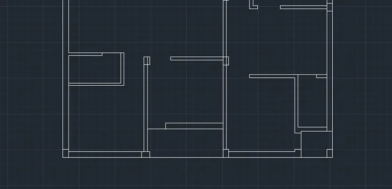
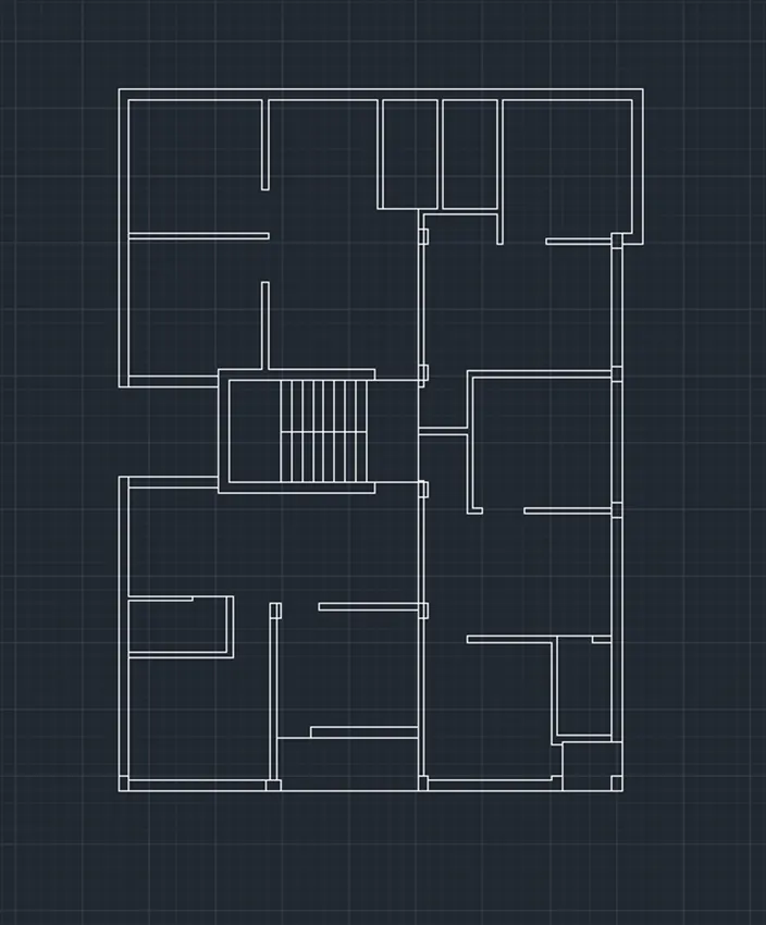
-
W1- 900 X 1200mm
W – 600 x 1200mm
W2- 1000x 1200mm
W3-1500 x1200mm
W4- 500x500mm
D- 1000X 2100mm
D1- 700 X2100mm
D2 -900 X2100mm
- Enter “DIMLINER” command in the command box.
- Check the dimension as per the drawing
- Enter “TEXT” command in the command box
- Give a “TEXT HEIGHT AS 150mm”
- Give a TEXTS as per the drawing and show the result
RESULT :
Aim:
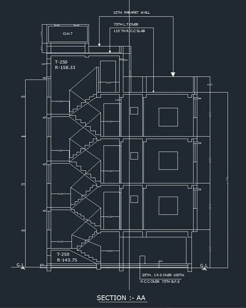
To create the Section -AA as per the drawing
Introduction :
Various command used while Sketching :
- Line command
- Unit command
- Lim max command
- XL command
- Zoom command
- Arc command
- Trim command
- Text command
- Extent command
- Fillet command
- Rectangle command
- Circle command
- Copy command
- LT command
- Dimension command
- Layer command
- Offset command
- Limits command
PRODUCTRE :
STEP 1 :
- GO to START MENU ,select AutoCAD 2018.
- Enter “UNITS” command in the command tab.
- Open “ Drawing units “ dialogue box , Type as “Decimal ” and precision as 00
- Then click units scale to “ millimetres ”
- Click “OK”.
- Enter “ LIM MAX” command in the command tab.
- Enter new value for Lim max as 20000’.
- Enter “zoom” command in the command box.
- Enter “All” command in the command box.
- Enter “LIMITS” command in the command box.
- Specify lower left corner as
- Enter “zoom “ command in the command box.
- Enter “ALL” command in the command box.
Step 2:
CREATING SECTION -AA :
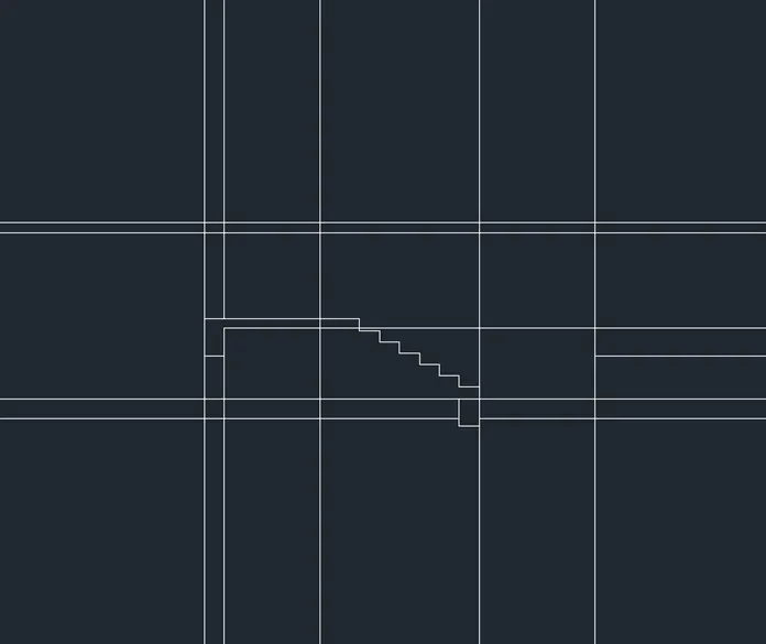
- Enter “Line” command in the command box .
- Give a value of “8900mm” horizontally
- Enter “Line” command in the command box .
- Next we have to draw another line from the previous line vertically with length of “1mm”
- Enter “Line” command in the command box .
- Next again draw the line form the previous line with the length of “11000mm” horizontally backwards from the previous line.
- Enter “Line” command in the command box .
- Now draw the line from the first line and last line was drawn previously
- Enter “OFFSET” command in the command box.
- Give a value of “125mm” for internal wall and “250mm” for external wall
- And give a ground level thickness is “200mm” and “150mm”
- Next we a to draw window in their requires places in 1st and 2nd and 3rd floor
- Next we have to draw the stairs with tread of “250mm” and the rise with “143.745mm”
- And take line type as dash line and set the particular value dash lines for the staircase
- Now we have to draw remaining parts, we draw the parapet wall and water tank (O.H.T)
- Now we have to draw the doors at their required places in the first , second and third floors.
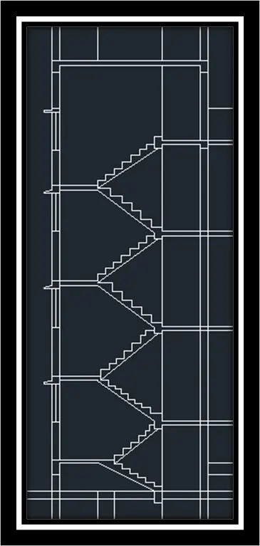
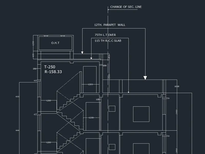
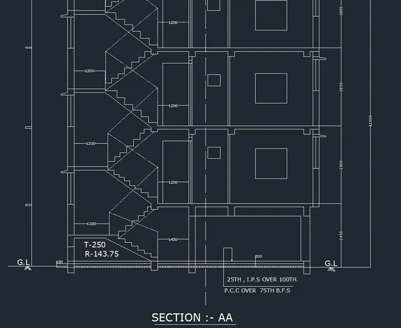
- Next remaining we draw the windows and sunshades in their particular places
- Enter “DIMLINER” command in the command box .
- Check all the dimension as per the drawing .
- Enter “MTEXT” command in the command box.
- Give a value of “150mmm” or “200mm” for the text hight ,
- Give a texts as per the drawing and show the result as per the drawing.
RESULT:
Aim:
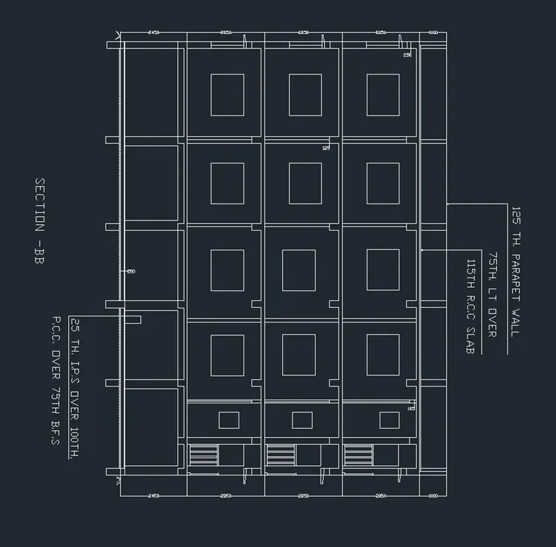
To create the Section -BB as per the drawing
Introduction :
Various command used while Sketching :
- Line command
- Unit command
- Lim max command
- XL command
- Zoom command
- Arc command
- Trim command
- Text command
- Extent command
- Fillet command
- Rectangle command
- Circle command
- Copy command
- LT command
- Dimension command
- Layer command
- Offset command
- Limits command
PRODUCTRE :
STEP 1 :
- GO to START MENU ,select AutoCAD 2018.
- Enter “UNITS” command in the command tab.
- Open “ Drawing units “ dialogue box , Type as “Decimal ” and precision as 00
- Then click units scale to “ millimetres ”
- Click “OK”.
- Enter “ LIM MAX” command in the command tab.
- Enter new value for Lim max as 20000’.
- Enter “zoom” command in the command box.
- Enter “All” command in the command box.
- Enter “LIMITS” command in the command box.
- Specify lower left corner as
- Enter “zoom “ command in the command box.
- Enter “ALL” command in the command box.
Step 2:
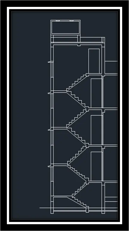
CREATING SECTION -BB :
- Enter “Line” command in the command box .
- Give a value of “11000mm” horizontally
- Enter “Line” command in the command box .
- Next we have to draw another line from the previous line vertically with length of “16388mm”
- Enter “Line” command in the command box .
- Next again draw the line form the previous line with the length of “11000mm” horizontally backwards from the previous line.
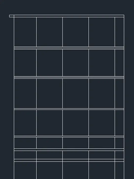
- Enter “Line” command in the command box .
- Now draw the line from the first line and last line was drawn previously
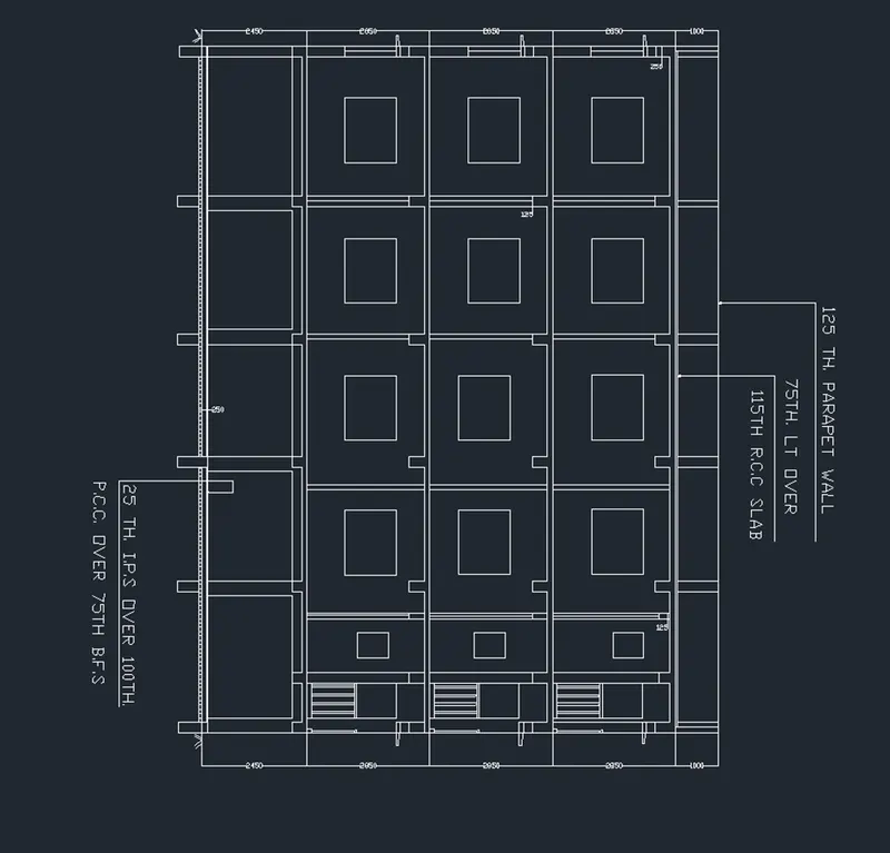
- Enter “OFFSET” command in the command box.
- Give a value of “125mm” for internal wall and “250mm” for external wall
- And give a ground level thickness is “200mm” and “150mm”
- Next we a to draw window in their requires places in 1st and 2nd and 3rd floor
- Next we have to draw the stairs with tread of “250mm” and the rise with “143.745mm”
- Next we have to draw the window in their requires places in 1st , 2nd and 3rd floors
- Next we have to draw the sunshade in the upside of the window protect from the sunlight,
- Enter “DIMLINER” command in the command box .
- Check all the dimension as per the drawing .
- Enter “MTEXT” command in the command box.
- Give a value of “150mmm” or “200mm” for the text hight ,
- Give a texts as per the drawing and show the result as per the drawing.
- Draw the section -BB as per the question and show the result.
RESULT: