Creating a Layout, Section and Elevation with dimensions using AutoCad
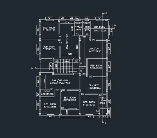
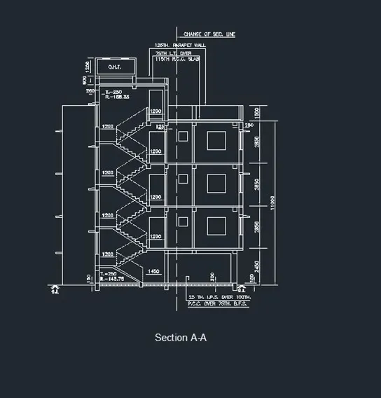
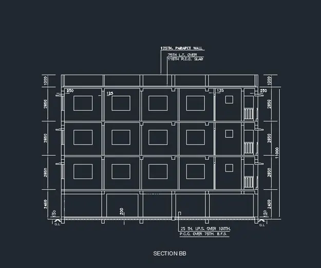
1.) AIM: To create the plan and sections as shown in the figures.
PROCEDURE:
- The units of the drawing sheet is set to Engineering precision.
- Construction lines are drawn both horizontally and vertically.
- The offset command is used with a distance of 250mm to produce an exterior wall that is 250mm thick. For internal walls, another offset of 125mm is generated.
- Similarly offset lines are created based on the room size and dimensions mentioned in the plan.
- In order to create the Section mentioned, construction lines are drawn as projections for the appropriate dimensions of the room size and locations of windows and doors.
- The floors are made after the projections from the design are produced for the location of the necessary portion.
- The stairs are drwan in accordance with the riser and thread dimensions.
- Similarly projections are created for Section BB to locate the columns and beams.
- The floors are drawn with appropriate height as mentioned in the given figure.
RESULT: