Creating a Layout, Section and Elevation with dimensions using AutoCad
Aim:- To Draw the given Plan and Section of the building by using AutoCad software.
Procedure:- Step 1: Type unit command and take length type in decimal or unit scale to millimeter.
Step 2: Take rectangle command from menu bar and start to draw the plan by creating rectangle first by calculating the dimension of the plan.
Step 3: Type offset command and create the rectangle by given thicness of the wall.
Step 4: Type line command and draw the plan by taking proper dimension as per given plan.
Step 5: Type trim(tr) command>undo and erase the unwanted lines.
Step 6: For Text type or select from home menu bar as multiline text and write the following name of the compartments as per given plan.
Step 7: For discontinuous line as shown in windows area. Select line and then properties of the line from menu bar and change the continuous line or select the line type as require by loading more type of lines.
Step 8: For dimensions to the components type dimlinear or select from menu bar and measure the lines. which give exact dimension to the components.
Result:-
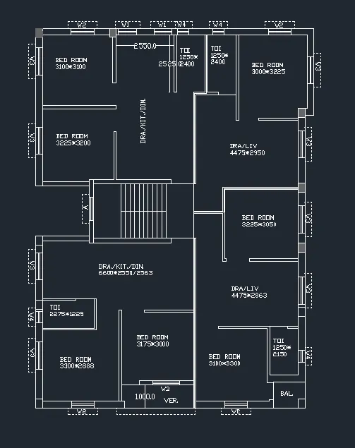
PLAN

SECTION A-A
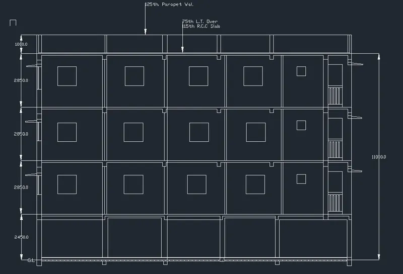
SECTION B-B