Creating a Layout, Section and Elevation with dimensions using AutoCad
1. Create the Plan and Sections as shown in the Figures. Use proper dimension techniques and dimension styles to document the project. Assume the sizes of the doors and windows as per construction standards. Refer to sections for stair details if required.
AIM:-
To create the given plan, elevation and section in AutoCAD by using proper dimension techniques and dimension styles. By assuming the sizes of the doors and windows as per construction standards and refer to sections for stair details if required.
INTRODUCTION:-
- Plans, elevations and sections are 2D visuals that represent a 3D object. Combining different 2D visuals allows you to create an accurate representation of a design.
- A plan view is a view of birds-eye view of a space. When drawing a floor plan, the roof would be removed so the interior space can be seen.
- A elevation view is a view from the side of an object, when drawing interior elevations, this would represent one of the walls. This would include any windows or doors as well as any built-in furniture that is in direct contact with the wall.
- A section view is a view which cut through of a space which will show more of the room’s features. It also allows you to show some structural detail. A section line can be cut from any part of the space, depending on what you would like to show.
PROCEDURE:-
1. PLAN:-
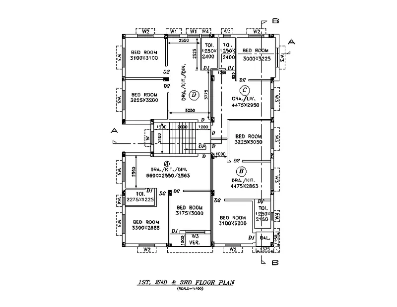
- First we have to open a new sheet in autocad and set the limits using the limits command.
- Next we have to draw the line with the length of 16388mm from down to up horizontally.
- Next we have to draw the line from the previous line with the length of 12150mm horizontally forwards.
- Next we have again draw the line from the previous line with the length of 16388mm downwards vertically..
- Next we have to draw the line from the last line to the first line to form the rectangle.
- Next we draw the rooms with help of line command and offset command and trim command, with the lengths given in figures.
- First we draw the bedroom with the length of 3100mm and width of 3100mm
- Next we draw the another bed room with the size of 3225mm x 3200mm.
- Next we draw the drawing/kit/din room with the size of 2550mm x 3775mm x 3250mm.
- Next we have to draw two toilets with the sizes of 1250mm x 2400mm.
- Nexr we have to draw the another bed room in the part C with the size of 3000mm x 3225mm.
- Next again we draw the dra/liv with the size of 4475mm x 2950mm.
- Next we draw the bed room in the part B with the size of 3225mm x 3050mm.
- Next we draw the dra/kit room with the size of 4475mm x 2863mm.
- Next we draw the toilet room wwith the size of 1250mm x 2150mm.
- Next we draw the another bed room with the size of 3100 x 3300mm.
- Next we have to draw the balcony with size of 1375mm x 1100mm.
- Next we draw the bed room in the A part with the size of 3175mm x 3000mm.
- Next we leave the some space for the veranda, with the length of 3175mm.
- Next we have to draw the another bed room with the size of 3300mm x 2888mm.
- Next we have to draw the toilet room with the size of 2275mm x 1225mm.
- Next we have to draw the dra/kit/din room with the size of 6600mm x 2550mm x 2563mm.
- Finally we draw the staircase with the size of 3200mm x 2400, the tread is 250mm and riser is 143.75 and 158.33mm.
- Next we have to trim the unnessesary lines and objects.
- Then we draw the columns with the size of 250mm x 350mm.

- Then place columns where ever they required in the floor plan.
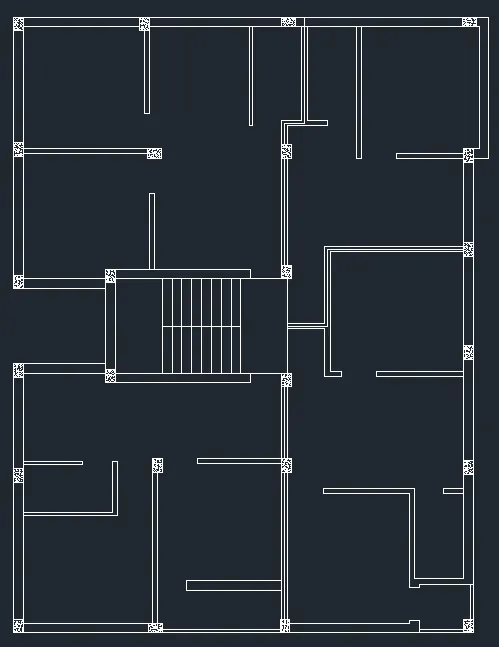
- Create the layers based the elements used and assign the colour to each of the element.
- Again with the help of layers command check by turn various layers on or off (displayed or not displayed), change layer colors, linetype, and display modes, as well as lock layers to prevent inadvertent or mistaken changes.
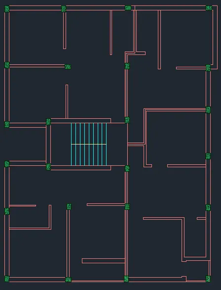
- Next drawn is windows and doors by assuming their sizes are shown below
Windows assumed size:
W1 - 1000 x 1200
W2 - 1500 x 1200
W3 - 1600 x 1200
W4 - 600 x 600
W = 1200 x 1200
Doors assumed size:
D - 1200 x 2100
D1 - 750 x 2100
D2 - 900 x 2100
- First drawn is windows as shown the figure with respective their dimension.

- Next placed the same sized windows based on the requirement as shown in the figure.
- Followed by draw the sunshade by using dotted line.
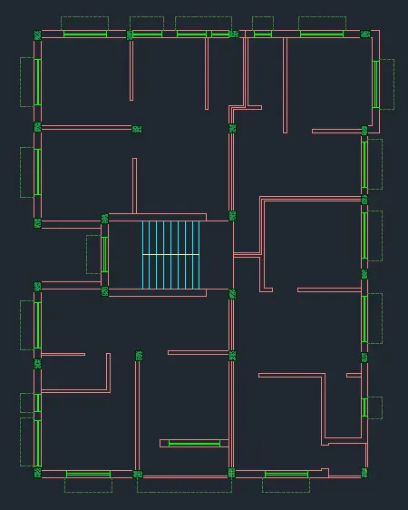
- Finally indicate the rooms using the single text command.
- And again we have to provide the dimensions for the given floor plan using the dimlinear command. If there is any possibility of using dimcontinue use the command.
- And also draw the section lines as given in the figure, and also indicate the doors and windows.
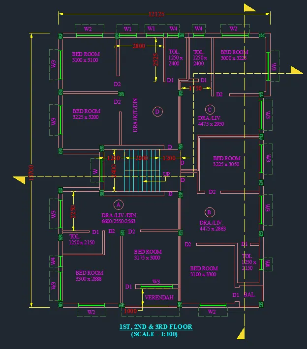
RESULT FOR PLAN IS SHOWN BELOW:-
To get the clear view of the plan which is drawn in AutoCAD. By using the zoom tool zoom the figure and then by using snipping tool cut the figure into two parts.
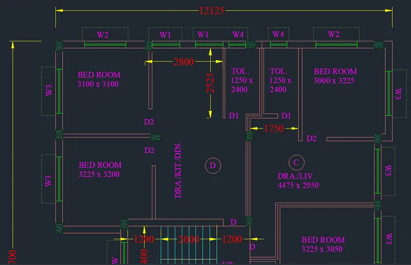
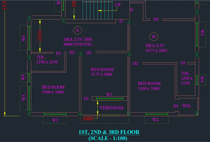
2. SECTION-AA:-
- First we have to draw the line with the length of 8900mm horizontally forward.
- Next we have to draw another line from the previous line vertically with the length of 1mm.
- Next again draw the line from the previous line with the length of 11000mm horiziontally backwards from the previously drawn line.
- Next draw the line from the first line and the last line we drawn previously.
- Next do thge offset to the particular lines with the given offset values.
- The inner wall offsets are 125mm and outer wall thickness is 250mm.
- And ground level thickness is 200mm and 150mm.
- Next we have to draw the windows in their requires places in 1st, 2nd and 3rd floors.
- Here next we have to draw the stairs with tread of 250mm and the riser with 143.75mm and 158.33mm.
- And take the line type as dashed lines and set it to the particular value of the dashed lines for the staircase.
- Next we have to draw the remaining parts, we draw the parapet wall and water tank(O.H.T) at the top of the building.
- Next we draw the doors at their required places in the first, second and third floors.
- Next remaining we draw the windows and sunshades in their particular places.
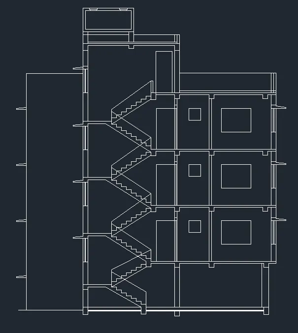
- Next we have to select layers and make them to the different colours for different parts in the section, as shown below.
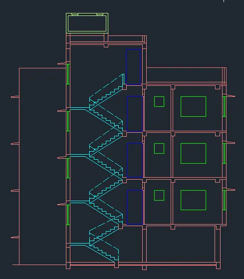
- Next we put the dimensions where ever they are required in the sectiion drawing as shown below.
- Next we have to select the single text command to indicate the parts in the section plan.
- Finally we have to draw the section line in the section plan as shown in the below figure.
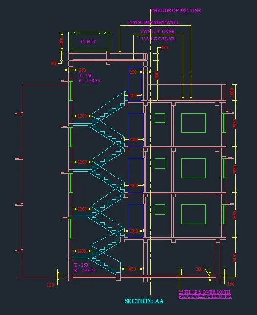
RESULT FOR SECTION-AA IS SHOWN BELOW:-
To get the clear view of the plan which is drawn in AutoCAD. By using the zoom tool zoom the figure and then by using snipping tool cut the figure into two parts.
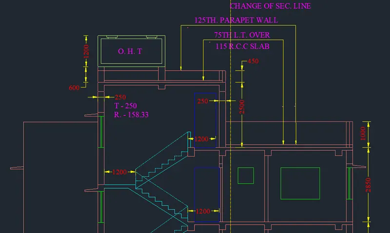
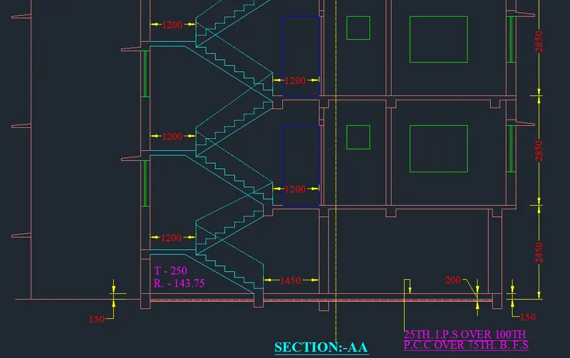
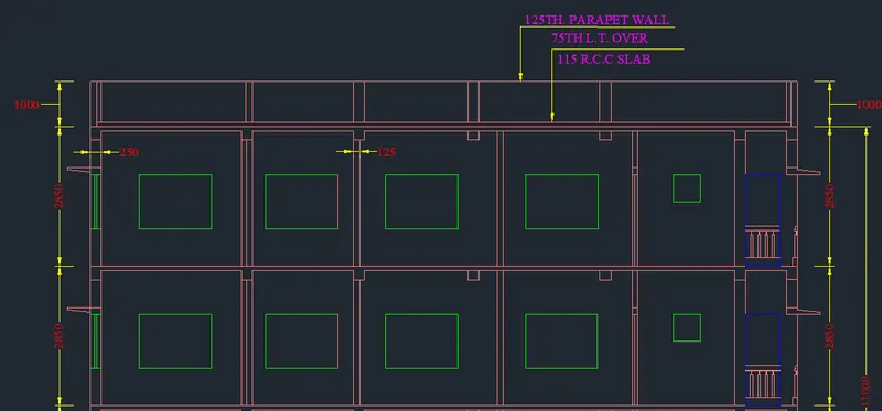
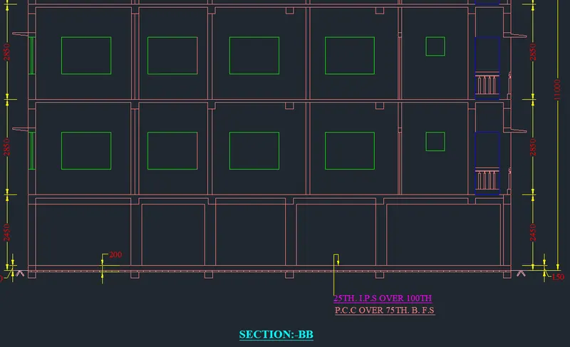
2. SECTION-BB:-
- First we have to draw the line with the length of 11000mm horizontally forward.
- Next we have to draw another line from the previous line vertically with the length of 16388mm.
- Next again draw the line from the previous line with the length of 11000mm horiziontally backwards from the previously drawn line.
- Next draw the line from the first line and the last line we drawn previously.
- Next do the offset to the particular lines with the given offset values.
- The inner wall offsets are 125mm and outer wall thickness is 250mm.
- And ground level thickness is 200mm and 150mm.
- Next we have to draw the windows in their requires places in 1st, 2nd and 3rd floors.
- Next we have to draw the windows in their requires places in 1st, 2nd and 3rd floors.
- Next we have to draw the sunshades in the upside of the window to protect from the sunlight.
- Draw the bolocany as per shown in figure.
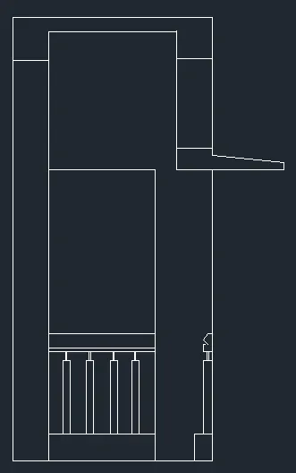
- Place the same figure as shown in above by using copy command.
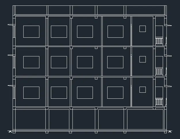
- Select the different colour layers for different parts in the section plan as shown below.
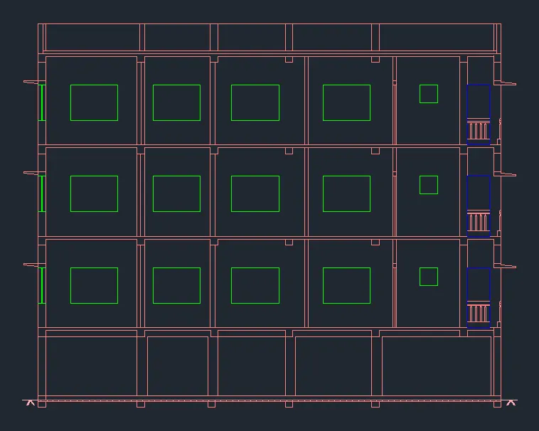
- Next we have to put the dimensions where ever they are required.
- And write the text to denote the parts in the section plan using the single text command.
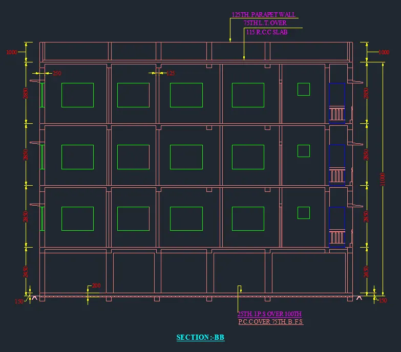
RESULT FOR SECTION-AA IS SHOWN BELOW:-
To get the clear view of the plan which is drawn in AutoCAD. By using the zoom tool zoom the figure and then by using snipping tool cut the figure into two parts.
______________________________________________***THE END***__________________________________________