Creating a Layout, Section and Elevation with dimensions using AutoCad
Q) create the plan and sections as shown in the figures.
use proper dimension techniques and dimension styles to document the project.
Assume the sizes of the doors and windows as per constructions for stair details. refer to srctions for stair details if required.
AIM:
To draw the floor plane and sections using the proper dimensions techniques and dimension styles to documents the project.
INTRODUCTION:
- Plan and sections are different types of drawing used by architechs to graphically represent a building desing and construction.
- A plan drawing is a drawing on a horizontally plane showing a view from above.
- An elevation drawing is drawn on a vertical plane showing a vertical depiction.
- A section drawing is also a vertical depiction but one that cuts throught space showing what lies whitin.
COMMAND USED:
- Limits command
- Line command
- offset command
- hatch command
- dimileaner command
- Dimstyle command
- Units command
- extend command
- fillet command
- trim command
- Join command
- line weight command
- Line type command
- Object snap command
PROCEDURE:
STEP1:
1st,2nd and 3rd floor plan:
- First we have to open the autocad and set the limits using the limtis command
- Next we have to draw the line with the length of 16388mm from down to up horizontally.
- Next we have to draw the line from the previous line with the length of 12150mm horizontally forward.
- Next we have to drawn again the line from the prevoius line with the klength of 16388mm downwards vertically..
- Next we have to drawn the line from the last line to the first line to form the rectangle.
- Next we draw the rooms with help of line command and trim command with the lengths given in figures.
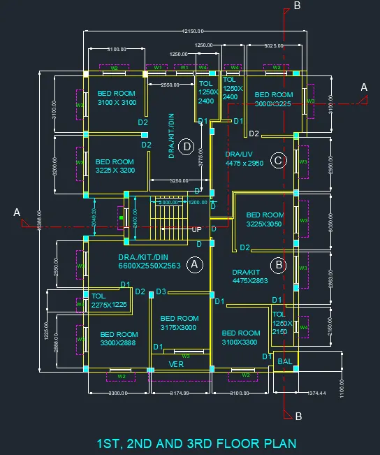
- First we draw the bedrooms with the length of 3100mm and width of 3100mm
- Next e draw the another bedroom with the size of 3225x3200mm
- Next we draw the drawings /kit/din room with the size of 2500mmx 3775mmx3250mm.
- Next we have to draw two toilets with the sizes of 1250mm x2400mm.
- Next we have to draw the another bedroom in the part c with the size of 3000mmx3225mm.
- Next again we draw the dra /liv with the size of 4475mm x 2950mm.
- Next we draw the bedromm in the part B with the size of 3225mmx3050mm
- Next we draw the dra/kit room with the size of 4475mmx2863mm.
- Next we draw the toilet room with the size of 1250mmx2150mm.
- Next we draw the another bedroom with the size of 3100x3300mm.
- Next we draw the balcony with size of 1375mmx1100mm.
- Next we draw the bedroom in the a part with the size of 3175mmx3000mm.
- Next we leave the some space for the veranda with the length of 3175mm.
- Next we have to draw the another bedroom with the size of 3300mmx2888mm.
- Next we have to draw the toilet room with the size of 2275mmx 1225mm.
- Next we have to draw the dra/kit/din room with the size of 6600mmx2550mmx2563mm.
- Finally we draw the staircase with the size of 3200mmx2400mm,the tread is 250mm and riser is 143.75 and 158.33mm.
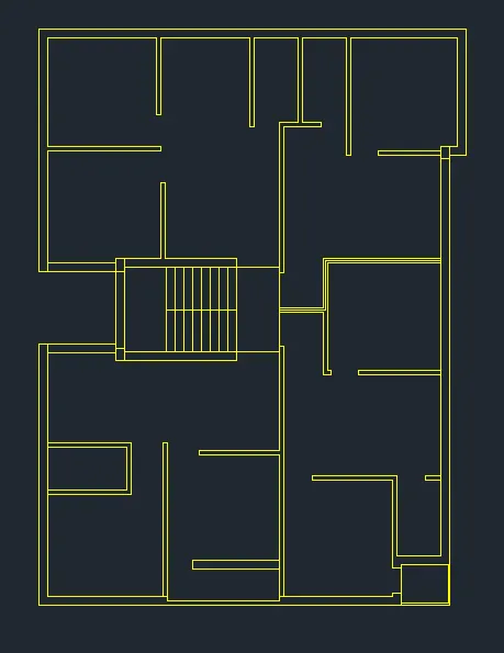
- Next we have to trim the unnessesary lines and objects.
- Then we draw the coloumns with the size of 250mmx350mm.
- The coloumn are placed where ever they required in the floor plan.
- And we specify the coloumn layer with the skyblue colour.
- Next we have to draw the windows and doors with the sizes are shown below,
- W1-900X1200mm
W-600X1200mm
W2-1000X1200mm
W3-1500X1200mm
W4-500X500mm
D-1000X2100mm
D1-700X2100mm
D2-900mmX2100mm
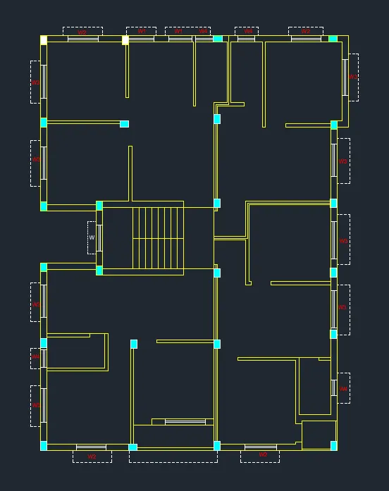
- Finally we indicate the rooms using the single text command.
- And again we have tto provide the dimrnsions for the given floor plan using the dimlinear command.
- And also draw the section lines as given in the figures and also indicate the doors and windows.
STEP2:
SECTION-AA:
- First we have to draw the line with the length of 8900mm horizontally forward.
- Next we have to draw another line from previous line vertically with the length of 1mm.
- Next again draw the line from the previous lines with the length of 11000mm horizontally backwards from the previous drawn line.
- Next draw the line from the first line and last line we drawn previously.
- Next do thge offset to the perticular lines with the given offset values.
- The inner wall offsets are 125 mm and outer wall thickness is 250mm.
- And ground level thickness is 200mm and 150mm.
- Next we have to draw the windows in their reqires places in 1st ,2nd and 3rd floors.
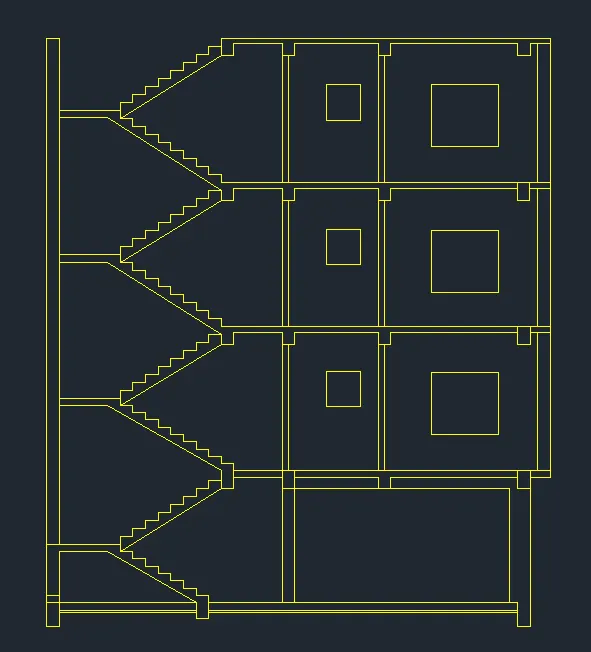
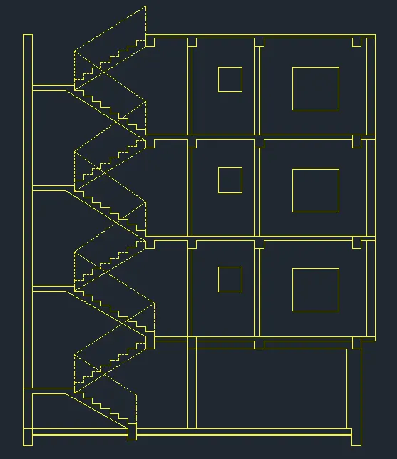
- Here next we have to draw the stairs with thread of 250mm and the riser with 143.75mm and 158.33mm
- And take the line type as dashed lines and set it to the particular value of the dashed lines for the staircase.
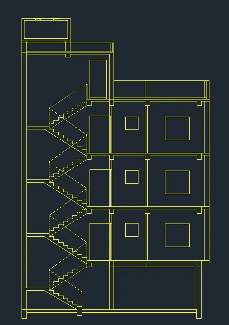
- Next we have to draw the remaining parts we draw the parapet wall and water tank at the top of the building.
- Next we draw the doors at their required places in the first ,second and third floors.
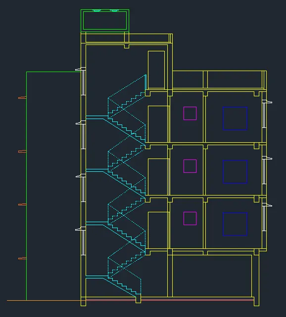
- Next remaining we draw the windows and sunshades in their particular places.
- Next we have to select layers and make them to differnt colours for differnt parts in the different section ,as shown below.
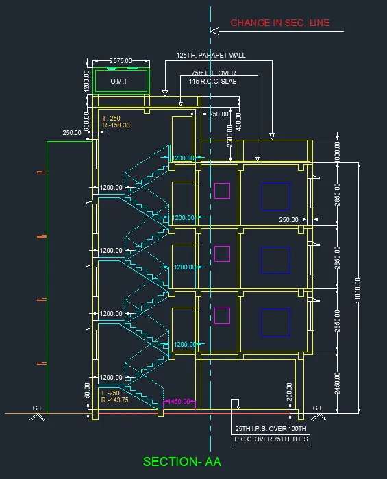
- Next we put the dimensions where ever they are required in the section drawing as shown below.
- Next we have to select the single text command to indicate the parts in the section plan.
- Finally we have to draw the section line in the section plan as shown in the below figure.
STEP3:
SECTION B:
- First we have to draw the line with the length of 11000mm horizontally forward.
- Next we have to draw another line frrom the previous line vertically with the length of 16388mm.
- Next again draw the line from the previous line with the length of 11000mm horizontally backwrds from the previous draw line.
- Next draw the line from the first line and the last line we drawn previously.
- Next do the offset to the particular lines with the given offset values.
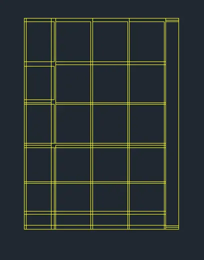
- The inner wall offset are 125mm and outer wall thicknessis 250mm.
- And ground level thickness is 200mm and 150mm.
- Next we have to draw the windows in their requires places in 1st 2nd and 3rd floors
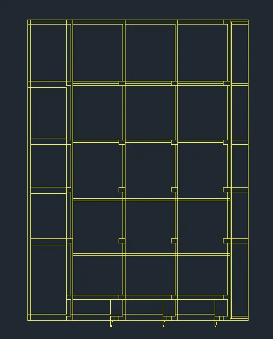
- Next we have to draw the windows in their requires places in 1st 2nd and 3rd floors
- Next we have to draw the sunshades in the upside of the window to protect from the sunlight.
- And we have to select the different colour layers for the different parts in the section plan as shown below.
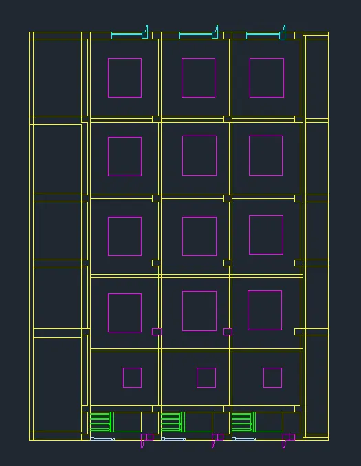
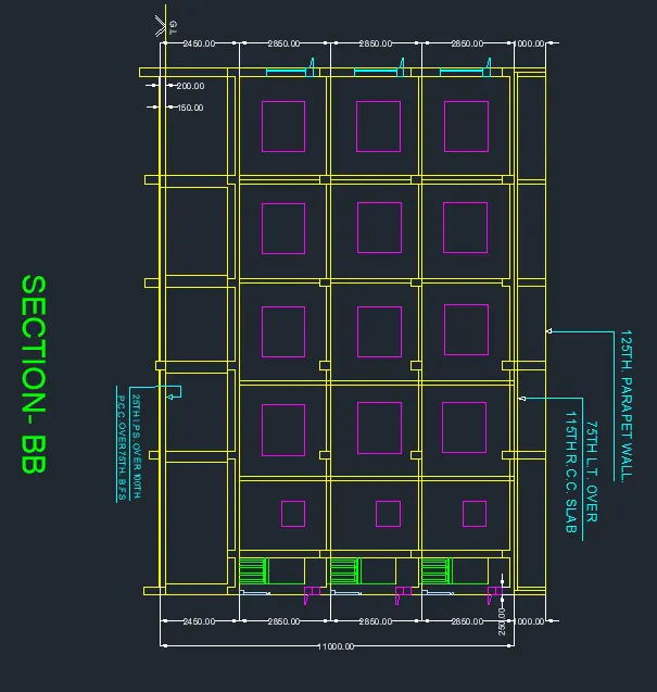
- Next we have to put the dimensions where ever they are required.
- And write the text to donate the parts in the section plan using the single text command.
RESULT:
- The 1st,2nd and 3rd floor plan and sections using the proper dimensions techniques are drawn successfully in the autocad in details manner.