Creating a Layout, Section and Elevation with dimensions using AutoCad
1. Create the Plan and Sections as shown in the Figures. Use proper dimension techniques and dimension styles to document the project. Assume the sizes of the doors and windows as per construction standards. Refer to sections for stair details if required.

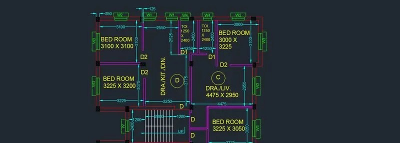
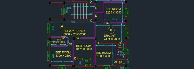


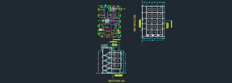
Aim: To Create the Plan and Sections of the given figure and tom use proper dimension techniques to measure the diagram.
Introduction: The given challenge conisits of a plan and two sections of the plan AA and BB respectively. The two sections are one in vertical and horizontal. The AA section in horizontal is not straight and change of sec line is mentioned in the section diagram. Layers are also used to differentiate the different parts of the plan. Proper dimension techniques are used and a layer is also created for the dimension.
Steps:
- Initially settings are done like units and limits. Metric system is used since the given diagram is in mm.
- Then two construction lines are drawn one in horizontal and vertical directons respectively.
- Then offset of 250mm is done for both lines and the lines in left i.e in -x direction and in bottom i.e in -y direction are trimmed using the trim option which sets the bottom boundary of the plan.
- Then in +y direction offset of horizontal xline is continued as per the dimensional requirement of the plan and in between the rooms wall are also included using the offset option
- After finishing the plan in +y direction the unwanted lines are trimmed whihc sets the left top corner of the plan
- Then the lines are offseted in +x directon as per the plan requirement and after the plan is finished in that direction the unwanted lines are trimmed which sets the right top corner of the plan and the offset is continued in the -y direction and the plan is finished
- In the proposed plan windows and doors are placed wherever required as per the plan
- For windows seperated blocks are created as W1,W2,W3 and W4 and are placed using the insert command wherever required
- Then the sunshade are projected outside in each windows and the line type of the projection is changed as per the plan
- Then each layers are defined like walls,windows,dimensions etc., and the obejcts of the plan are designated into the layers
- After that dimension style is fixed from the dimstyle command and the whole plan is dimensioned under the dimension layer created
- Each color is assigned for each layer for differentiating the objects.
- Then Text style is fixed and using mtext command details of the plan such as Room name,size are inserted in the plan and the plan is finished
- Then using xline command lines are projected in bottom direction for the section AA
- The a line is drawn and the GL of the section is fixed and the unwanted lines are trimmed.
- Then using the offset option as per the height of the building given the lines are offseted in +y direction and after the parapet wall and the unwanted lines are trimmed to fix the top of the buliding
- The windows are drawn as per the plan and the sunshade of the windows on side is drawn in each floor level
- Then on the left side of the section AA diagram stairs are drawn as per the given Tread and Rise and the doors are drawn and a O.H.T is drawn
- At the bottom 100thk PCC is drawn and hatched using the Hatch command
- Finally dimensions are done for the diagram in the dimension layer and markings are also included using the Mtext command
- Then for the section BB diagram the lines are projected in +x direction using the xline command
- Then a line is drawn in vertical direction and the GL of the section is fixed and a 100thk PCC is drawn and hatched
- Then as per the height of the building lines are offseted in +x direction and after the parapet wall the unwanted lines are trimmed and top of the building is fixed
- Then the balcony grill projection is drawn in the right corner of the section BB
- Finally the dimensions are marked in dimension layer and the markings are inserted using the mtext command wherever required.
Results: The given plan and the section diagrams are drawn and layers are assigned to differentiate between objects of the plan. A unique dimenion style is created and the options of dimensions such as dimcontinue are used. The usage of xlines and usage of dimstyle command is understood clearly. Some of the markings are inserted using the multileader and the style of the mleader are known from the mleader menu.