Creating a Layout, Section and Elevation with dimensions using AutoCad
CREATING A LAYOUT, SECTION AND ELEVATION WITH DIMENSIONS USING AUTOCAD
INTRODUCTION:
Dimensioning in AutoCAD:
- AutoCAD provides a whole range of dimensioning tools which can be used to quickly dimension any drawing without the need for measurement.
- AutoCAD dimensions are special blocks which can be easily edited or erased as necessary.
- AutoCAD divides dimensions into four main categories: Linear, radial, angular an ordinate.
Linear dimension commands:
- These are used to dimension along straight lines.
- There are five linear dimension commands, namely: DIMLINEAR, DIMCONTINUE, DIMBASELINE, DIMALIGNED, DIMROTATED.
- DIMLINEAR command is probably the most commonly used dimension command.
- This tool can be evoked from toolbar, pull down--> dimension--> linear.; Keyboard Command: DIMLINEAR.
Continue dimension command:
- This command can be used to add a string of dimensions which aligns perfectly.
- This tool can be evoked from toolbar; pulldown-->dimension--> continue; Command : DIMCONTINUE.
- First we have to DIMLINEAR command , the rest can be continued using DIMCONTINUE command.
Baseline dimension command:
- This tool can be evoked from toolbar; pulldown-->dimension--> baseline; Command : DIMBASELINE.
- This command can be used to generate a series of dimensions from a single base point.
- First dimension have to created using DIMLINEAR command the rest can be created using DIMBASELINE command.
Aligned dimension command:
- This tool can be evoked from toolbar; pulldown-->dimension--> Aligned; Command : DIMALIGNED.
- This command is used to create aligned dimensions. These are dimesnions along inclined lines which cannot be dimensioned with the DIMLINEAR dimension command because that command will only give a measured dimension in either a horizontal or vertical direction.
- DIMCONTINUE and DIMBASELINE commands can be used in conjunction with DIMALIGNED dimensions.
Radial dimension command:
- There are mainly two radial dimension commands, DIMRADIUS and DIMDIAMETER.
- Both commands result in a similar looking dimension, so AutoCAD automatically inserts a R to indicate a radius and the dimension symbol (%%c) to indicate dimension.
Diameter dimension command:
- This tool can be evoked from toolbar; pulldown-->dimension--> diameter; Command : DIMDIAMETER.
- Diameter command can be used to annotate a circle or an arc.
- To achieve this simply start the command, pick a point on the circumference of the circle, pick a second point to determine the length of the leader and then add the dimension text.
Radius dimension command:
- This tool can be evoked from toolbar; pulldown-->dimension--> radius; Command : DIMRADIUS
- This commnd is identical to the diameter command except that the dimension is radius and theresulting dimension is prefixed with "R" to indicate radius.
Angular dimension command:
- This tool can be evoked from toolbar; pulldown-->dimension--> Angular; Command : DIMANGULAR.
- This command is flexible and can be used to indicate an angle in almost any situation.
Ordinate dimension command:
- This tool can be evoked from toolbar; pulldown-->dimension--> ordinate; Command : DIMORDINATE.
- This command is used to annotate co-ordinate points with X or Y points
- This may be useful for setting out onsite plans.
Annotation with leaders
Leader command:
- This tool can be evoked from toolbar; pulldown-->dimension--> leader; Command : LEADER.
- This command can be used to annotate any point on a drawing.
Dimension text edit command:
- This tool can be evoked from toolbar; pulldown-->dimension--> align text--> options; Command : DIMTEDIT
- This command is used to modify the text position of any single dimension.
Dimension edit command:
- Command: DIMEDIT.
- Command is used to modify and change the text o any number of dimensions.
Dimension update command:
- This tool can be evoked from toolbar; pulldown-->dimension--> update; Command : DIM UPDATE.
- This command is used to apply the current dimension style to existing dimesnions.
Aim:
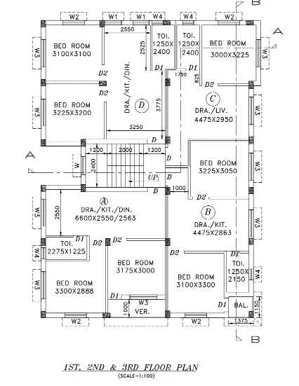
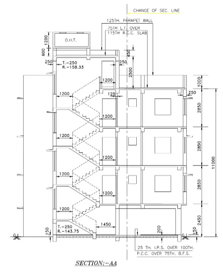
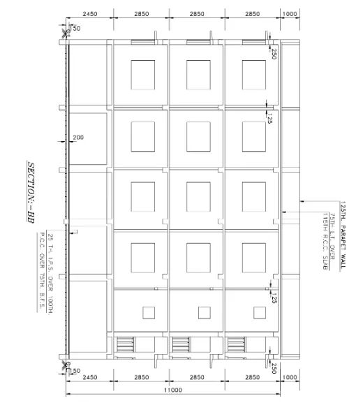
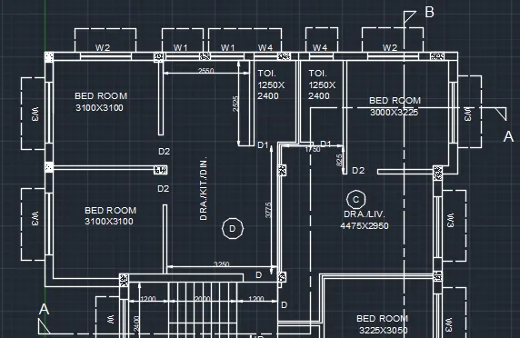
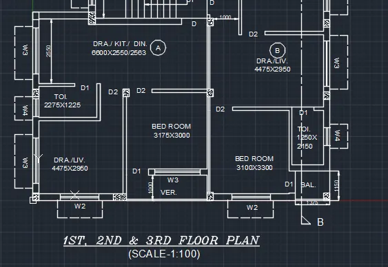
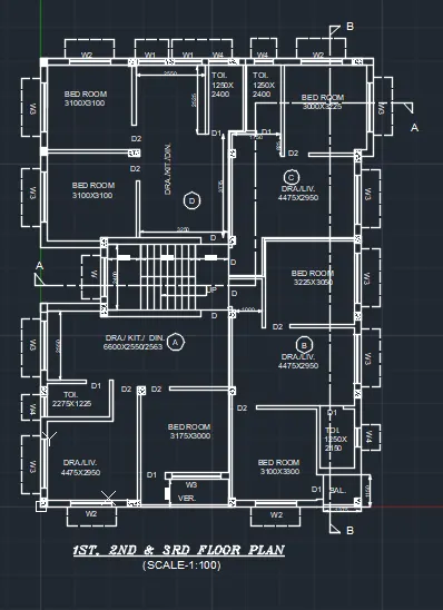
To create the plan and sections as given by using proper dimension techniques and dimension styles.
Procedure:
- Initially set the units of the drawing as Decimal (millimeters).
- Now, set the limits of the drawing:
- Specify the lower left corner: (0,0)
- Specify the upper right corner: (40000,52000)

- Plan:
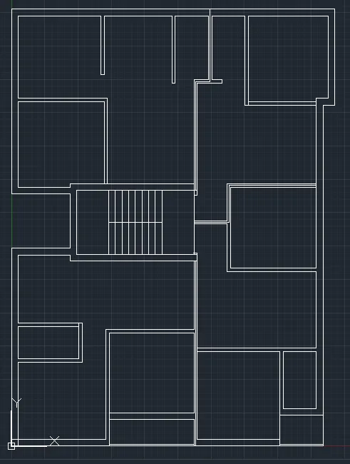
- Now, choose the line command and draw rectangle having dimension 12150x16388.
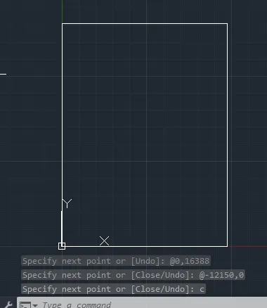
- Now, by offsetting the lines different rooms can be created. External walls are having thickness of 250mm and internal walls are having thickness of 125mm.
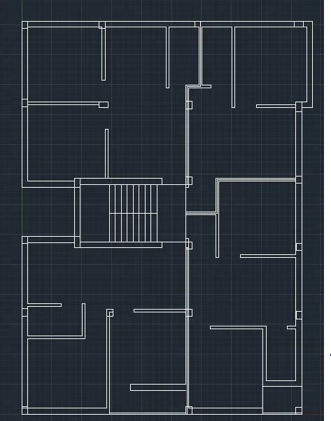
- Now, place the columns and position the doors in the plan.
- The place windows in the appropriate positions.
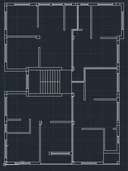
- Now, provide appropriate hatchings to the column.
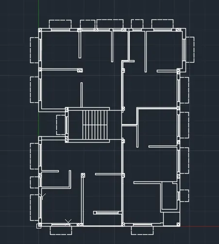
- Now, complete the drawing by providing the dimensions and text.
- Also,mark the sections as marked in the given figure.
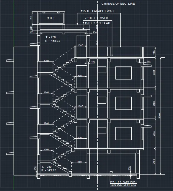
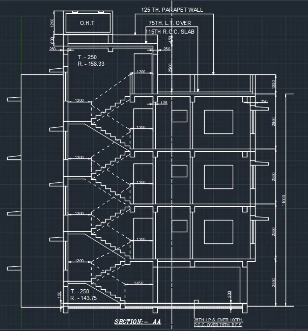
- Section:-AA
- Inorder to draw the section, initially choose the Xline and elevate the prts through which the given section cuts.
- choose line command and draw the out line of the section as per the dimensions given in the figure.
- Staircase section is also drawn using line command; staircase connecting groundfloor and 1 st floor has riser dimension as 143.75mm and tread dimension as 250mm.; The rest of the staircse has riser dimension as 158.33m and tread dimension as 250mm.
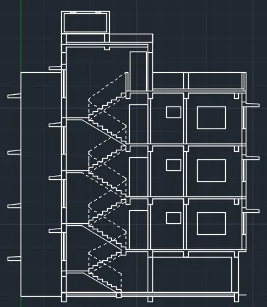
- Now the section is completed by providing necessary texts and dimensions.
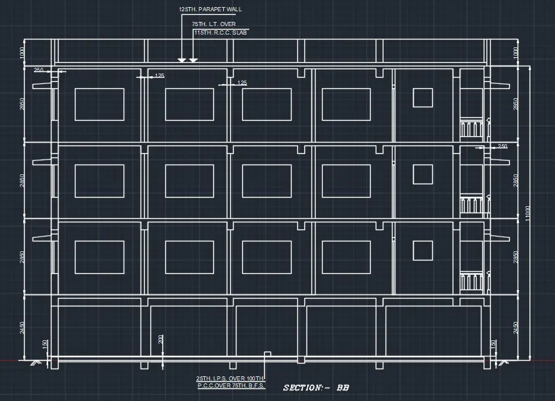
- Section BB:
- Inorder to draw this section, choose Xline command(horizontal) and elevate the elements side ways from the section given in the plan.
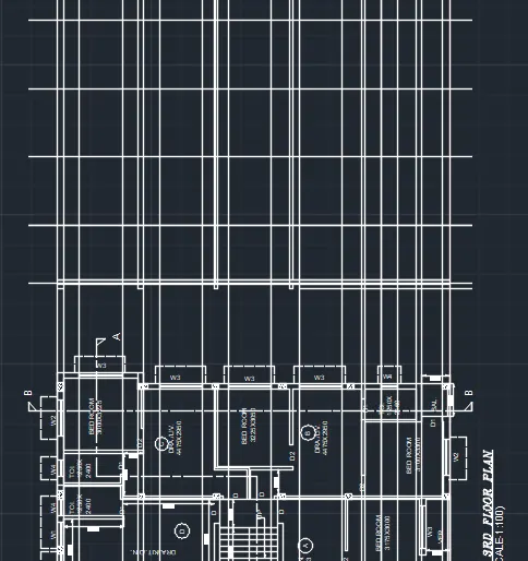
- Now create the outline of the section and then trim off the unwanted lines.
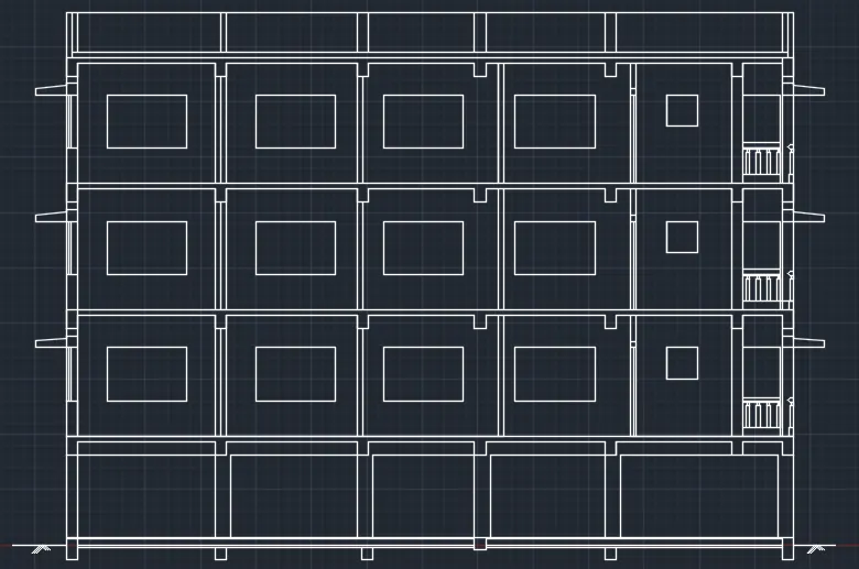
- Now, complete the figure by providing necessary texts and dimensioning it.
Result:
The plan, Section AA and Section BB of the given drawing is completed and is obtained as follows:
1. Plan:
2. Section AA:
3. Section BB: