Creating a Floor plan, Footing detail and Isometric view using AutoCad
Aim: To create the MODEL OF C1, C2, C3, C4, C5 and C6 IN Autocad software and explaining the procedure in report format shown as a given below.
INTRODUCTION:
- Open the Autocad software from destop or go to the start>all program>Autocad.
- Click New to open a new drawing.
- Type L and enter this is a command for using the commands line command.
PROCEDURE:
For C1:
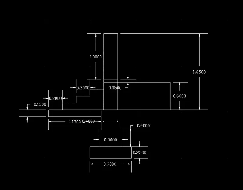
LOAD BEARING WALL OVER SPREAD FOOTING.
TO create the cross section of LOAD BEARING WALL OVER SPREAD FOOTING.
Set the units to decimal, and millimeters, then enter.
Then, type L enter for line command,
specify the first point 1,1 and press enter.
Then as per the given figure dimensions drawn below using the line command.
For C2:
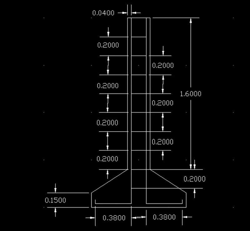
ISOLATED FOOTING:
TO create the cross section of ISOLATED FOOTING.
Set the units to decimal, and millimeters, then enter.
Then, type L enter for line command,
specify the first point 1,1 and press enter.
Then as per the given figure dimensions drawn below using the line command.
For C3:
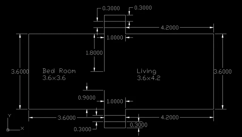
LINE DIAGRAM OF A TWO BEDROOM BUILDING.
Set the units to decimal, and millimeters, then enter.
Then, type L enter for line command,
specify the first point 1,1 and press enter.
Then as per the given figure dimensions drawn below using the line command.
For C4:
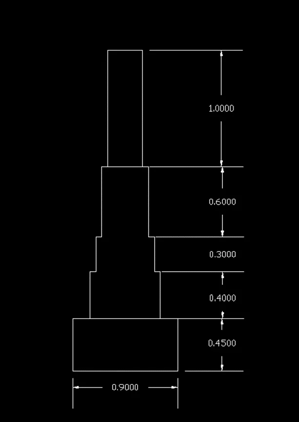
Cross section of LOAD BEARING WALL SHOWING FOUNDATION DETAILS:
Set the units to decimal, and millimeters, then enter.
Then, type L enter for line command,
specify the first point 1,1 and press enter.
Then as per the given figure dimensions drawn below using the line command.
ISOMETRIC DRAWINGS:
A 2D isometric drawing is a planar represents of a 3D isometric projections.
Isometric view quickly communicates about the model for better understandings in addition to the other projection methods.
In AutoCAD, Isometric drawings are drawn using Iso-planes.
By using the ISODRAFT command, several system variables and settings automatically changed to values that facilitate isometric angles.
Followings are the Iso-planes in AutoCAD.
- Right- Aligns snap and grid along 30- and 90- degree axes.
- left- Aligns snap and grid along 90- and 150- degree axes.
- top- Aligns snap and grid along 30-and 150- degree axes.
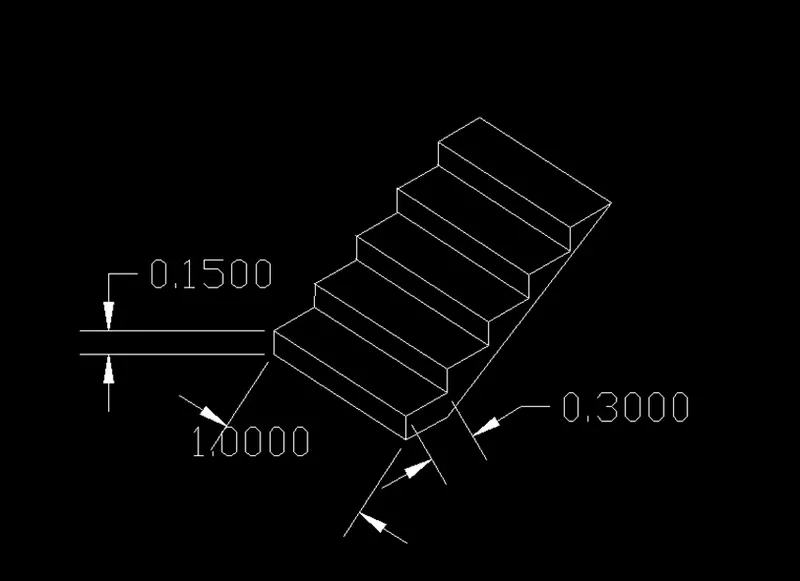
For C5:
ISOMETRIC VIEW OF STEPS:
Then, type L command to the command box, and enter
specify the first point 1,1 and press enter.
Then as per the given figure dimensions drawn below using the line command.
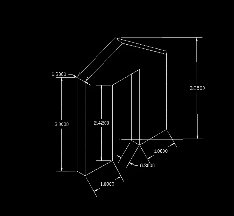
For C6:
ISOMETRIC VIEW OF CABLE WALL:
Then, type L command to the command box, and enter
specify the first point 1,1 and press enter.
Then as per the given figure dimensions drawn below using the line command.
Result:
Created the MODELS of
C1,
C2,
C3,
C4,
C5 and
C6
using AUTOCAD software and explained the procedure in detailed.