Creating a Floor plan, Footing detail and Isometric view using AutoCad
1. Floor planning:
Aim: To create a floor plan using the tools in auto cad 2020 , here am using polyline tool to draw the floor plan.
Procedure:
step1. in the command prompt the unit system and select engineering unit system.
step2. now in the command section prompt polyline or type Pl.
step3. now specify the 1st point by giving coordinates or using cursor.
step4. now with the help of 1st point and with the help of reference diagraw mention the next required point.
step5 continue the process until the last point as menstioned in the drawing nd requirement.
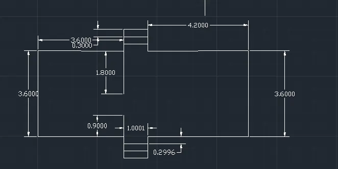
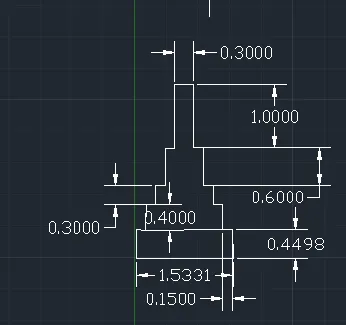
2. Cross section of load bearing wall showing foundation details.
Aim:to draw the c/s of lod bearing wall showing foundation details with the help of tools in autocad 2020.
procedure:
step1. in the command prompt the unit system and select engineering unit system.
step2. now in the command section prompt polyline or type Pl.
step3. now specify the 1st point by giving coordinates or using cursor.
step4. now with the help of 1st point and with the help of reference diagraw mention the next required point.
step5 continue the process until the last point as menstioned in the drawing nd requirement.
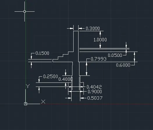
3.Cross section of load bearing wall over spread footing
Aim:To draw Cross section of load bearing wall over spread footing with the help of autocad 2020.
Procedure:
step1. in the command prompt the unit system and select engineering unit system.
step2. now in the command section prompt polyline or type Pl.
step3. now specify the 1st point by giving coordinates or using cursor.
step4. now with the help of 1st point and with the help of reference diagraw mention the next required point.
step5 continue the process until the last point as menstioned in the drawing nd requirement.
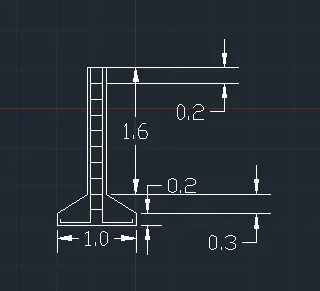
4.Cross section if isolated footing
Aim:To draw a c/s of isolated footing with the help of autocad 2020
procedure:
step1. in the command prompt the unit system and select engineering unit system.
step2. now in the command section prompt polyline or type Pl.
step3. now specify the 1st point by giving coordinates or using cursor.
step4. now with the help of 1st point and with the help of reference diagraw mention the next required point.
step5 continue the process until the last point as menstioned in the drawing nd requirement.
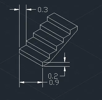
5. Isometric veiw of stairs.
Aim: to draw isometric view of steps with the help of autocad.
Procedure:
step1. In the command prompt or type unit system and select engineering unit system.
step2. now in command promot Ds and select isometric snap and entre ok
step3. now select line tool and with the help of isometric drafting start drawing line with required step.
step4. now in command prompt Co for copying the drawn step and copy it 5 times.
6.Isometric view of gable wall.
Aim:to draw isometric view of gable wall with autocad 2020.
Procedure:
step1. In the command prompt or type unit system and select engineering unit system.
step2. now in command promot Ds and select isometric snap and entre ok
step3. now select line tool and with the help of isometric drafting start drawing line with required points. to complete the wall.