Creating a 3D rendered model for a Residential Building in AutoCad
Aim: To draw a residential building in 3d and create the rendered view.
Residential building with G+ 8 floors with 4 units in each floor.
- Creating 2d plan.
- Making 2d plan into 3D .
- Assigning materials.
- Camera settings.
- Rendering.
Commands used:
- Extrude.
- Offset.
- UCS.
- Box.
- Union.
- Subtract.
- Move.
- 3d orbit.
- Boundary.
- Solid edit.
- Material attach.
- Material browser.
- Camera settings.
- Lighting settings.
- Render.
Procedure:
Open AutoCAD, select metric, make the settings to 3d modelling.Set the limits and zoom all.
To draw a 8-floors apartment building with 4 apartments in one floor.
Creating 2D plan:
Step 1:
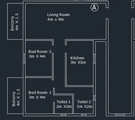
Creating first apartment in first floor:
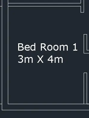
Bedroom 1 :
With line command draw 3m x4m and offset 0.25m for the outer wall and 0.125m for the internal wall.
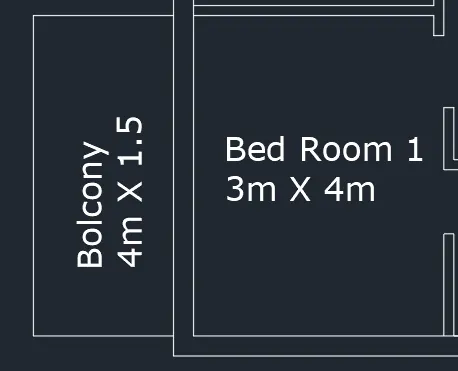
Balcony :
For balcony from the bedroom offset 1.5m horizontally and 4m vertically.
Give the wall thickness as 0.25m.
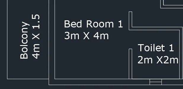
Toilet (B-1) :
Draw an offset of 2m horizontally and 2 vertically.
Give wall thickness as 0.125m.
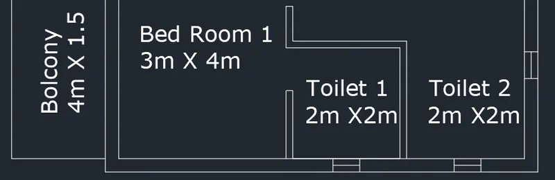
Toilet 2:
Copy the toilet to the adjacent side so that toilet 2 is formed.
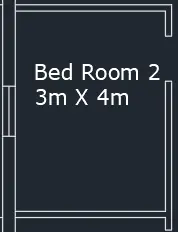
Bedroom 2:
From the Bedroom-1 offset 3.0m horizontally and 4m vertically.Give wall thickness of 0.125m for inside wall and 0.2m for external wall.
Living room :
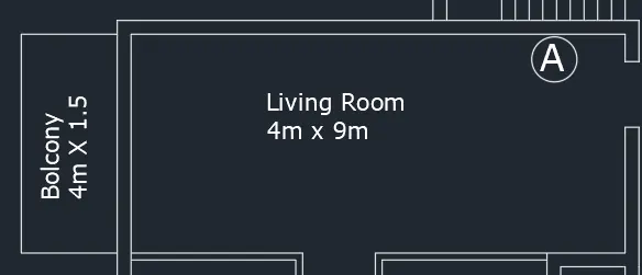
Offset the the line from bed room-2 at adistance of 4m horizontally and 9m vertically. and give the wall thickness as 0.25m.
Balcony- For balcony from theloving offset 1.5m horizontally and 4m vertically.
Give the wall thickness as 0.25m.
Kitchen:
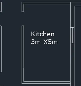
Draw an offset from living room at a distance of 5m and give the offset of 1.35m from bed room -2and from then give the wall thicknesss as 0.125 and give an offset of 3m and give the wallthick ness as 0.25m.
Create door openings:
1x2.1m for main door
0.9x2.1m for room doors
0.8x2.1m for toilet doors
Sliding door is placed in balconies 0.1m width.Glass door for kitchen.
Place the windows by creating as blocks and inserting them:
w1- 1x1.2m
v- 0.5x0.5m
Text -All bedrooms are marked with multiline text command and dimensions are written.
Trim all the unwanted line a and fillet the corners.
1st apartment:
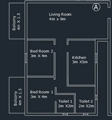
Provide an offset from apartment 1 at a distance of 2.6m for the path way and give the wall thickness as 0.25m.
Creating apartment B:
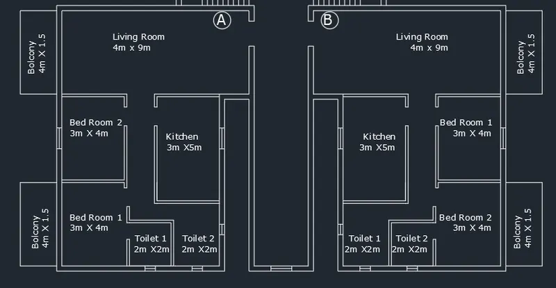
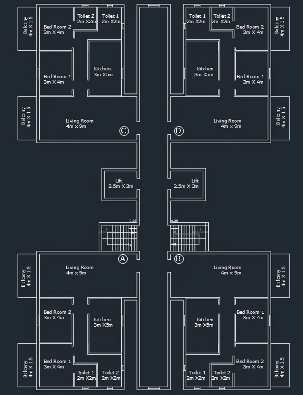
Mirror the apartment1 after making it a group with basepoint as mid point of path way and mirror line vertically.
Step 2:
Creating main staircase:
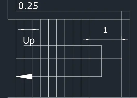
From the B type apartment offset 2.4m width and offset 0.2m for wall thickness.Offset 1m from the end for the landing.
Tread = 0.25m and riser=0.15m, so total of 20 steps as the height of 1 floor is 3m.
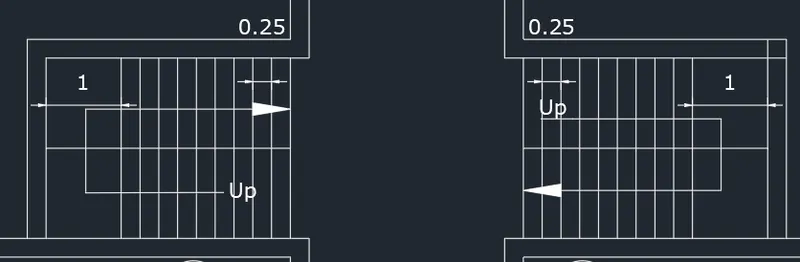
Mirror the steps to the other side.
Step 3:
Creating lift wall:
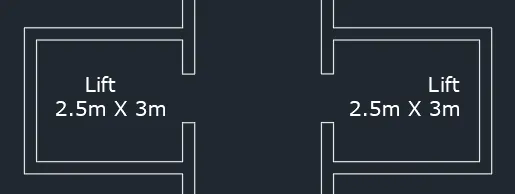
Create a lift pit of 2.5 x3 m, with wall thickness 0.25m at adistance of 2m from the stair case.
Copy the same on the other side for the second one.
Create 1m door for lift.
Step 4:
Creating C and D appartments:
Mirror the A and B type on the other side leaving a distance of 2.0m from the lift.
2D plan of first floor :
Making 2d plan into 3D :
Step 5:
Creating region for extrusion:
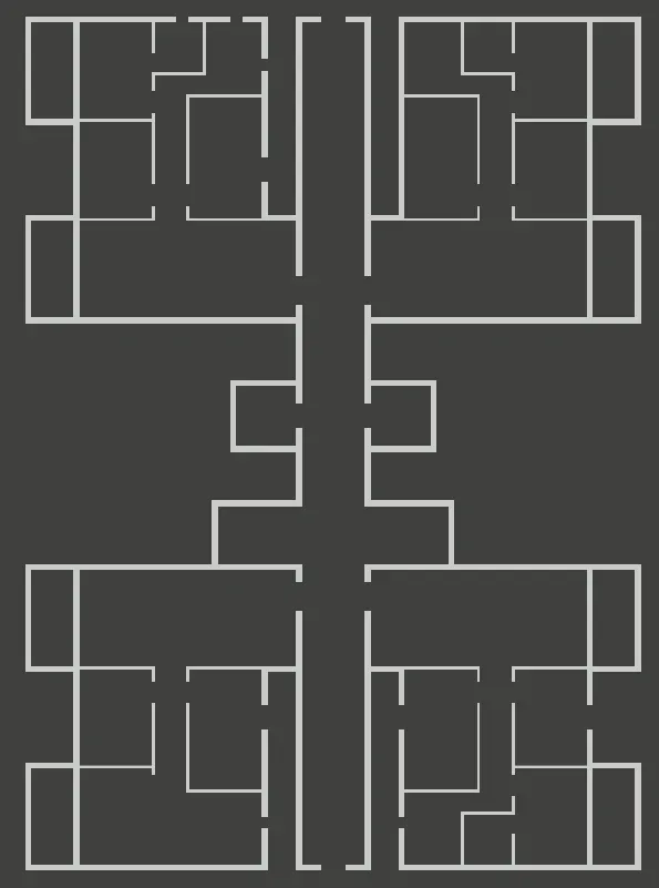
Copy the 2d plan .First create region by boundary command.
For balconies region are created separately, as the height of wall is 1.5m.It is done by "BO" command.
Step 6:
Creating different layers:
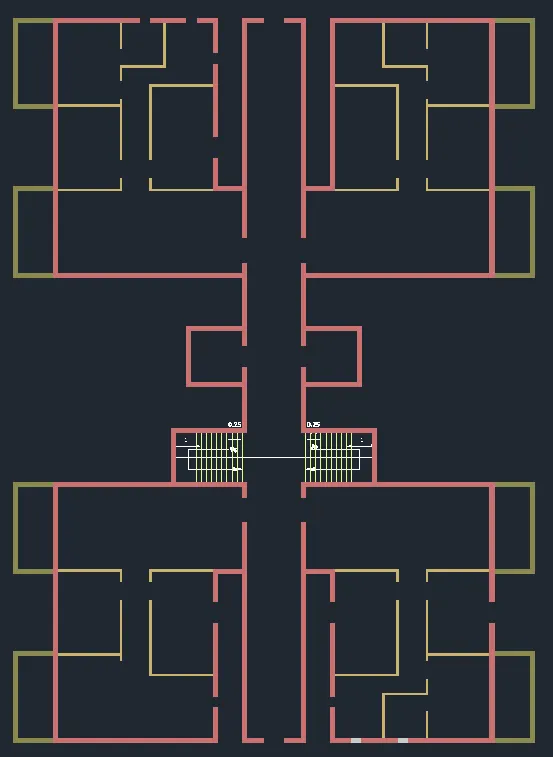
Make different layers for the full wall and half wall - walls of balconies, stairs and place the region in respective layers.
Step 7:
Extruding the walls:
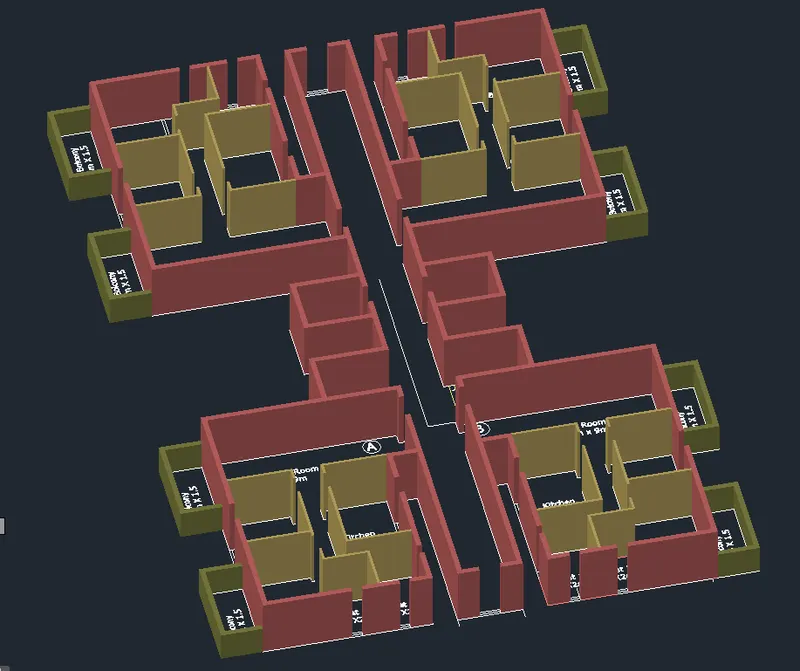
Select all the wall region, full wall and extrude it by 3m.
Extrude the half walls by 1.5m, all the balcony walls.
Step 8:
Creating window opening:
Create a rectangle at the bottom part of the window and extrude it 0.9m upwards till sill level.
Also create a rectangle at the top and extrude it downwards 0.9m.
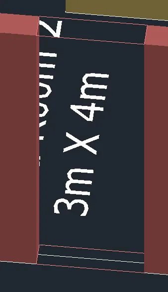
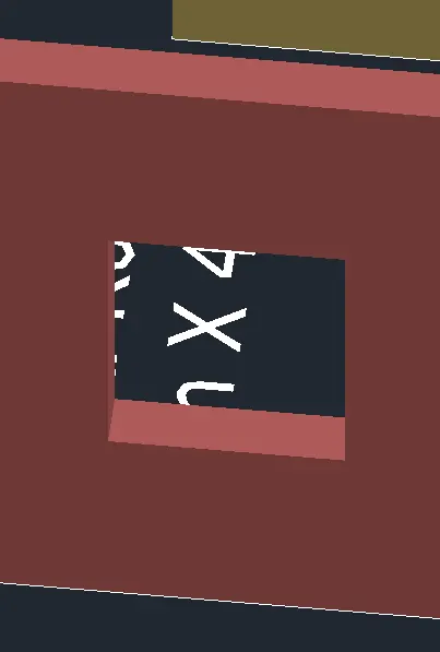
Similarly extrude all walls and create window opening.
Step 9:
Creating ventilator opening:
Create opening for ventilator 0.5 x0.5m.Similarly create rectangle and extrude 0.9m from top and 1.6 from the bottom.
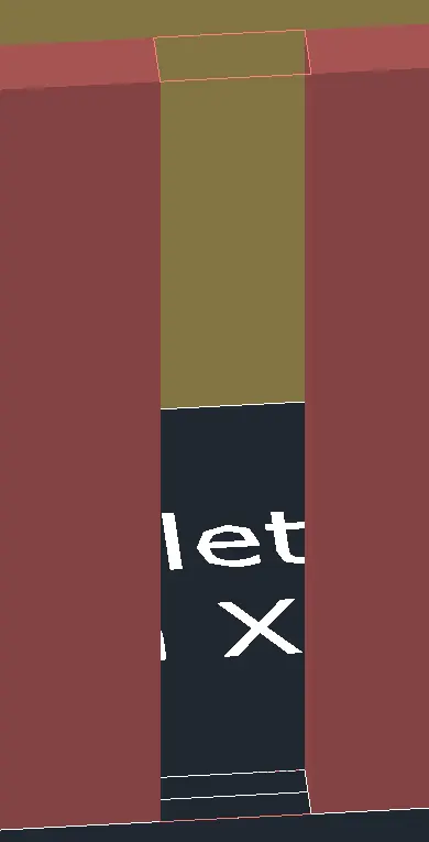
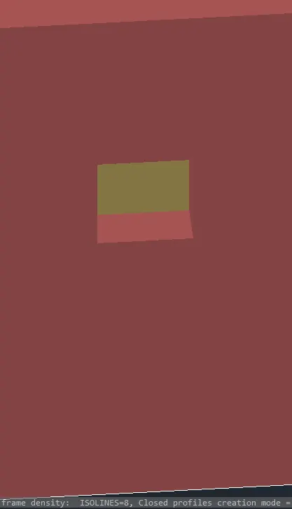
For lift door, create a rectangle at top and extrude -0.9m.
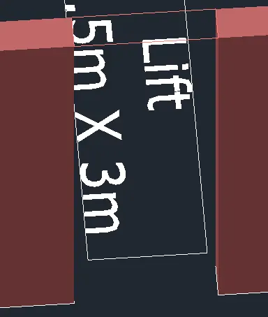
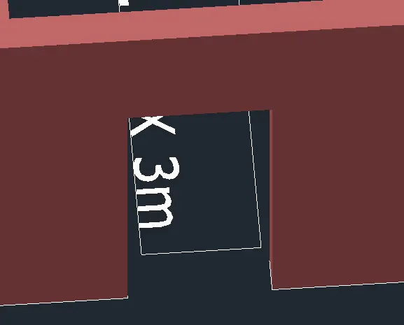
For all the doors also create a rectangle at top and extrude 0.9m downwards, lintel level.
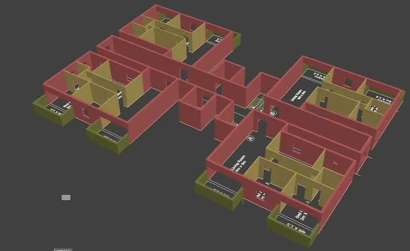
For the lobby opening, create rectangle and extrude 1.5m for the beam.
Step 10:
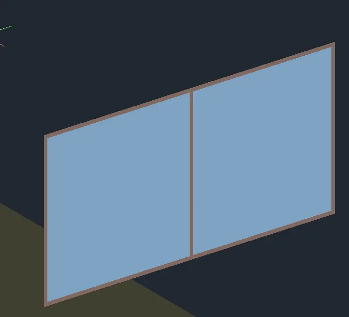
Creating window:
With ucs command place the ucs on the face of window.Create a rectangle in the opening of the window.
Move the rectangle to side to create frame mullions and glass.
Create offset of at mid-point to create 2 panels.
Offset 0.02m for the frame, and 0.05 for the mullions trim the edges.

By "bo" command create a region for the frame.
Use subtract command and subtract the frame region from the entire.
Create a layer for window frame and insert the region to the layer.
Extrude frame by 0.075m backwards.
Mullions:
Again with “Bo" command create region for mullions.Subtract it from the entire region.
Place it in the layer created for mullions.
Extrude it by 0.03m.
For glass:
Create region for glass by "BO" command.
Make it a layer called glass- window.
Extrude it by 0.015m.
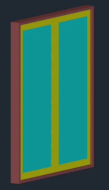
Select the mullions and with move command move it by 0.015m. Command "M”, specify the base point, then for second point give @0,0, -0.015, such that frame is projected outwards.
Step 11:
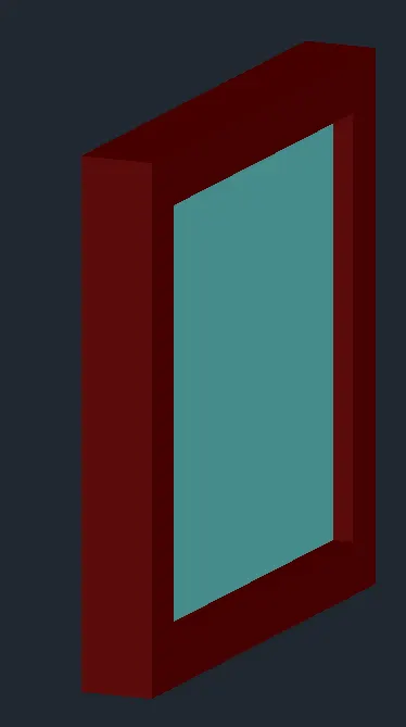
Creating ventilator :
Draw a rectangle of 0.5 x0.5 and offset 0.05for the frame. Create region for frame and glass and extrude it by 0.07 and 0.03
Place it in the respective positions
Step 12:
Creating door
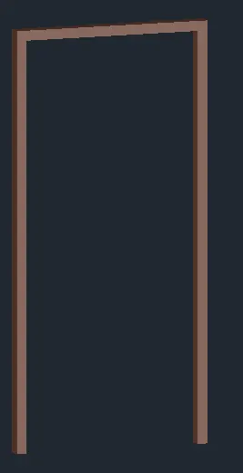
Create a layer for door frame and door shutterWith the help of polyline draw the outline of frame
offset 0.05m for the thickness of frame.join the bottom of frame by line.
Then by join command make it a single profile
Extrude it by 0.1m., thickness of frame.
Step 13:
Creating door shutter
Create a profile by polyline by snapping end of the frame.Extrude it by -0.02, thickness of frame.
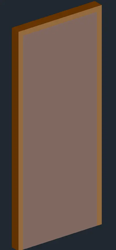
Make the door as group and palce it where ever required.
Step 14:
Creating door for balcony for living and master bedroom:
Create a frame by rectangle, offset 0.05m and create region and extrude by 0.075.Similarly, create region for glass and extrude it by 0.02m.
Step 15:
Creating 3d steps for main stair:
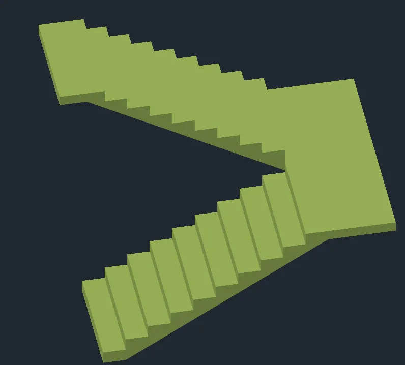
Go to top view and draw the section of stair with riser 0.175 and tread 0.25m.
Waist slab thickness as 0.15m.
Now create a region and extrude it 1.2m(width of stair)
Similarly, for the next flight, place the ucson the face of the landing, then draw the section of stair., hide or turn off the layer of other objects to work smoothly.
for the landing slab to extend, create a rectangle on the side face of slab.Extrude it till 1.2m width of 2nd flight.
Similarly, for the second flight also.
Make it union by union command so that it becomes single selection.
Step 16:
Creating handrails:
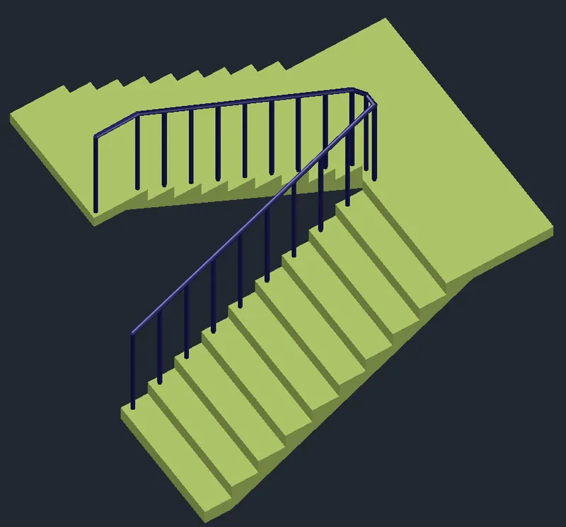
Place the ucs on the tread.Make a circle of 0.02m radius.
Extrude it to a height of 1m. copy it in each thread.
For handrail, create 3d polyline over the balusters and create a circle of 0.03m.With sweep, select the circle then the polyline.
Step 17:
Creating main floor::
Create layers for main floor, toilet floor and balcony floor,
Go to top view 2d wireframe, and with the help of polyline draw the outline of floor inside the wall balcony with main floor layer.
Step 18:
Creating ground floor:
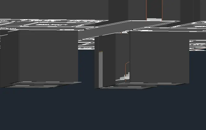
Copy one flight of steps to the bottom of both the stairs.Copy the lift pit walls also.
Step 19:
Creating columns:
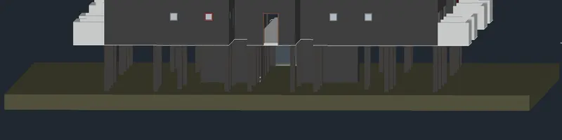
Go to top view in 2d wireframe model, then draw the columns wherever necessary.Extrude it to a depth of -3m.

Create a rectangle and extrude to show the ground.
Assigning materials:
Step 20:
Adding materials:
Go to visualise tab, and click on material browser,Click on Autodesk library and click on the required material.
For wall select paint, then select the colour and click on add materials to the document.Off all other layers so that the selection becomes easy.
Select the wall and click on the paint selected in the material browser.
By "MATERIALATTACH" command we can select the material to the required layer.
In the material attach browser drag the material to the layer.
For glass- clear glass is given
For door shutter, select the wood and select cocobolo the appearance dialogue box select image and select wood
For frame, select teak and we can change the stain colour.
Then by material attach select the material and attach to frame.
Similarly, for flooring, give different materials for main floor ., bathroom floor and balcony.
We can edit the scale, colour of the image in the dialogue box which appears by clicking on the image.
To attach a new material, click on create new material from the bottom of the material browser.
Step 21:
Creating top floors:
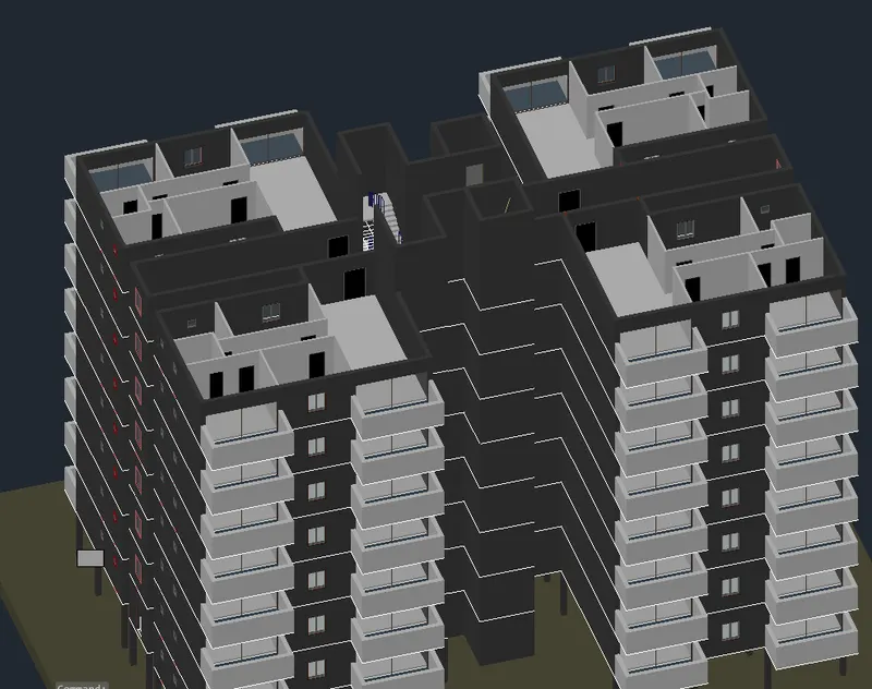
Copy the first floor, Hiding the ground floor copy-select base point array , enter the number as 8, select the 2nd point at 3m from the frist floor .
Step 22:
Copy the floor for the roof slab:
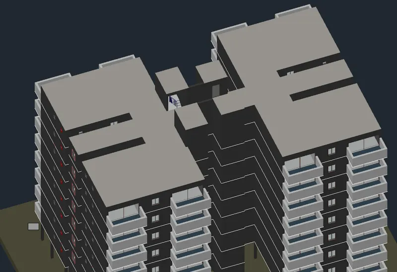
Copy the stair and create a stair head room to enter to the terrace.
For lift also create a lift room, also create roof in 2dplan and then extrude by 0.15m slab thickness and place in 3d.
Step 23:
Creating parapet walls:
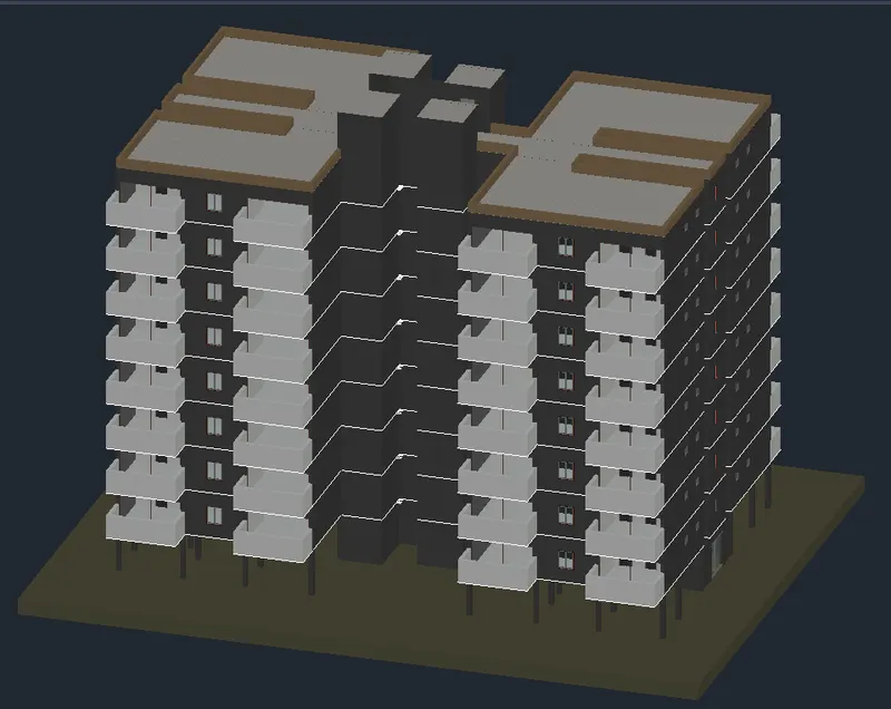
Parapet wall is created by using polysolid and extruding 0.6m .
Step 24:
Setting the exposure conditions, sunlight etc before rendering:
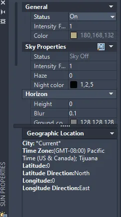
Go to visualize tab, on all shadow option.
Click on sun status and give date and time, time is given as 3 p.m.
In rendering option, click on the environment and exposure condition, change the exposure condition in the dialogue box.
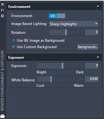
Click on use custom background, and in gradient option give top colour as blue and bottom as white for the effect of sky.
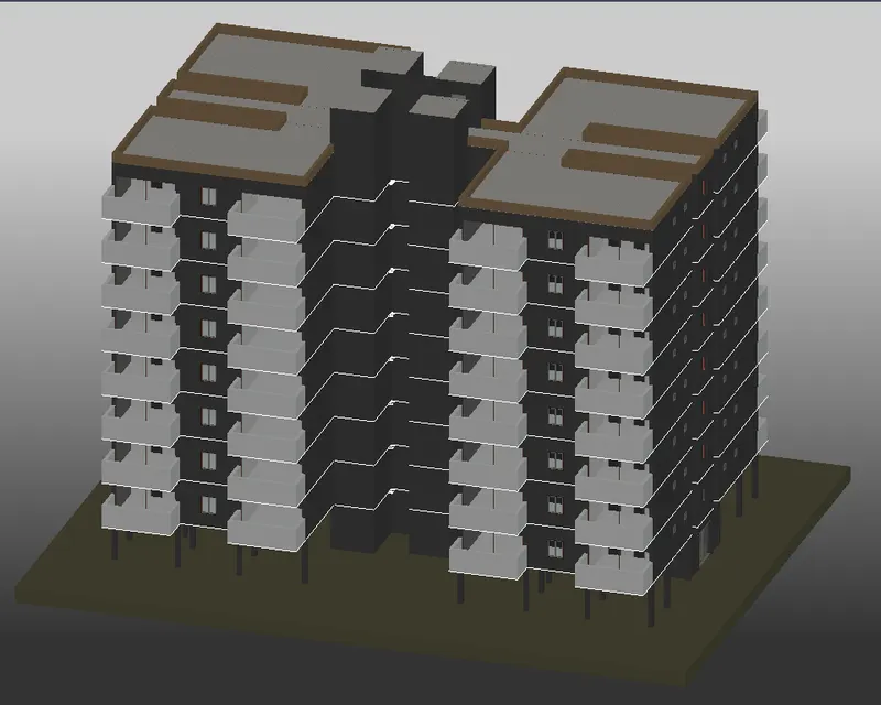
Render the image.
Camera settings:
Step 25:
Setting the lights and camera:
Click on spot light from the visualize tab, place the light by creating a cylinder for the positioning of the light.
Click on the target where light ray has to be displayed.Click on distant light and place it in the entrance, adjust the intensity and intensity factor.
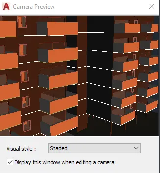
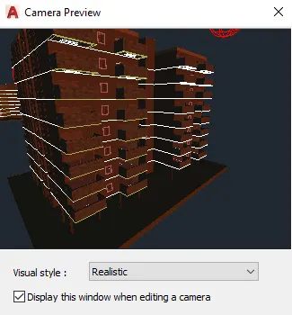
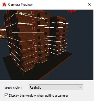
Click on camera, and place the source point , then select the point where the image has to be captured.
In the preview box we can see the image and adjust the view.
As such 2 cameras views are created.
Cam 1:
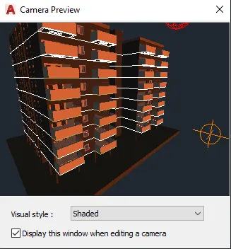
Cam 2:
Rendering
Step26:
Rendering:
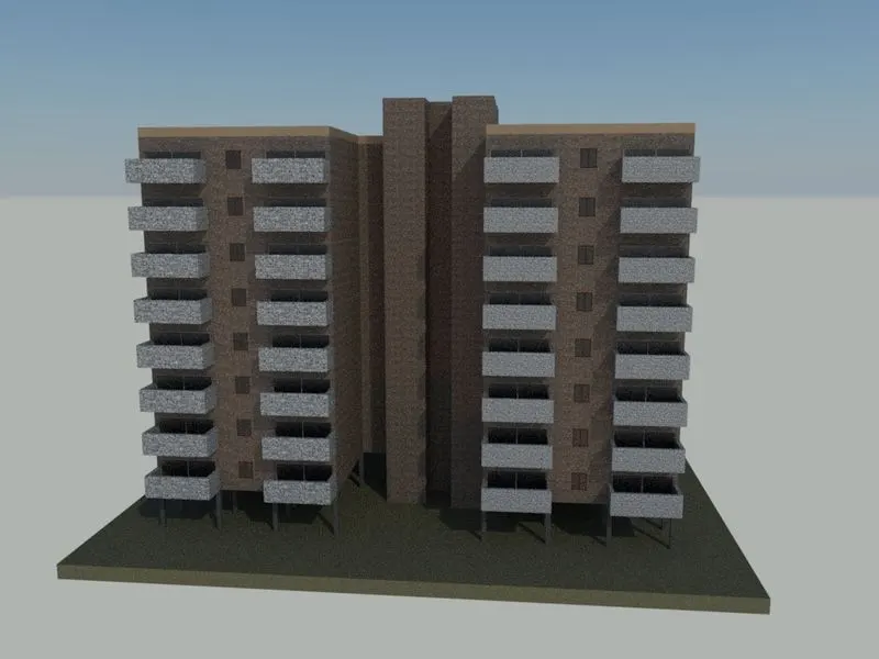
Click on the view "Camera view " created, click on sky background option and on it.
Click on medium render
Then click on the render option to render the image.
Cam 1:
Cam 2:
Result:
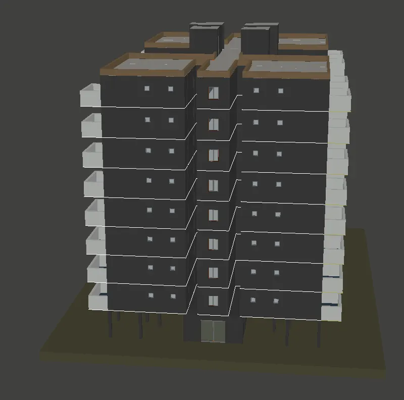
Front view:
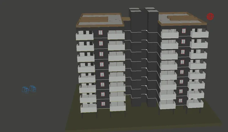
Right view:
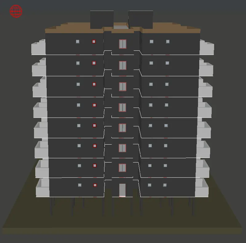
Back view:
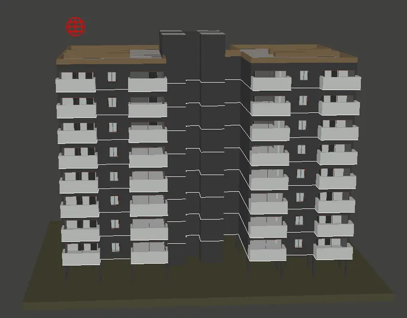
Left view:
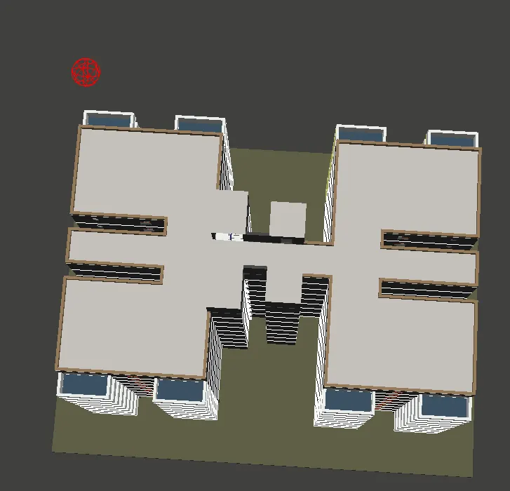
Top view:
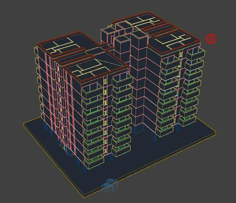
Hidden Model:
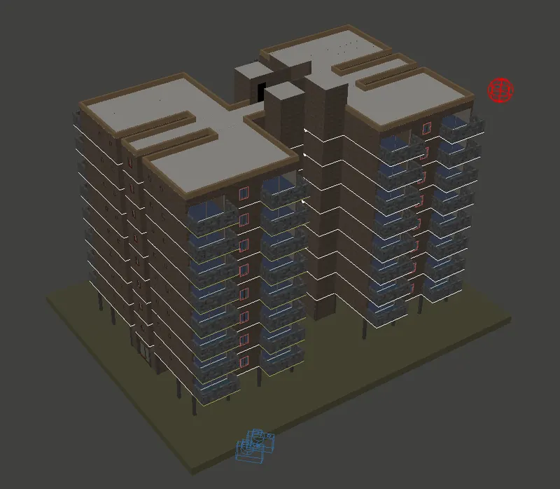
Realistic Model:
Rendered Model: