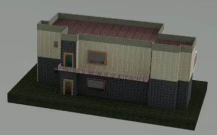
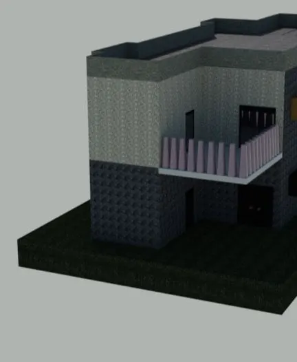
Creating a 3D rendered model for a Residential Building in AutoCad
Aim:
To Create a 3d imensinal model of the residential building with a rendered view
Procedure :
- In the command prompt type units >0'-0" > engineering > inches
- In the command prompt type limmax > 100',100,
- In the command prompt type limits >0',0'
- In the command prompt type z>a
- In the command prompt type l > to draft the desired lines
- In the 3d model it is changed to top view to draw the plan
- In the ribbon bar > select layers > to create layers for walls , doors , windows
- In the plan view the steps are also drawn with R-(6") , T-1'
- In the command prompt type XL to draw the infinite lines
- In the command prompt type adc ( Design centre ) to add the interior components like sofa , dinning table , kitchen , utility room , Bedroom , Toilet .
- In the command prompt type offset is used to give the thickness of the wall of dimensions 4"
- In the command prompt type trim to trim the extra lines
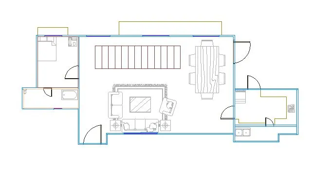
- In the command prompt type Mt to give the text
- In the command prompt type dim to give the dimensions
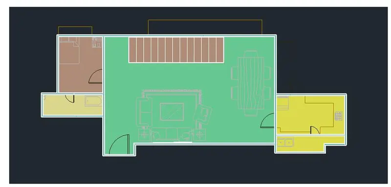
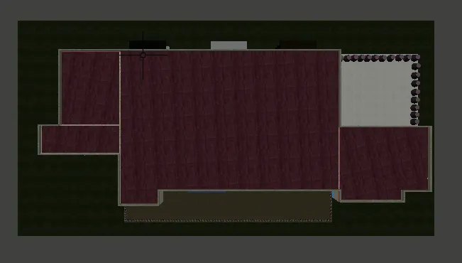 ( top view )
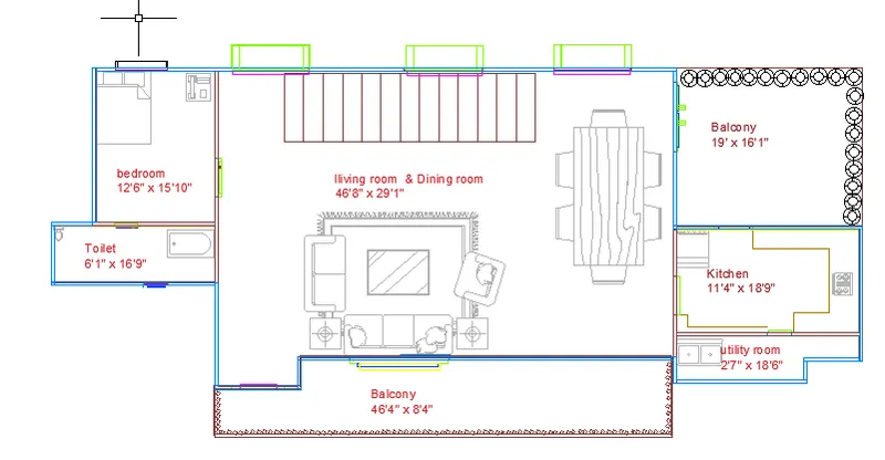
- The Dimensions are bedroom ( 12'6" x 15'10" ) , toilet ( 6'1" x 16'9" ) , Living & dining room ( 46'8" x 29'1" ) , Balcony (19' x16'1" ) , Kitchen ( 11'4" x 18'9" ) , utility room ( 27" x 18' 6" )
- after the plan is created in the top view we go to south west view
- In the south west view , In the command prompt type extrude or we can select it from the ribbon bar
- With the help of the extrude command only the walls are extrude
- The window and doors are not extruded
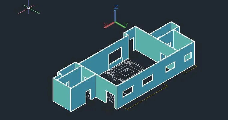
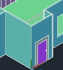
- In the command prompt type rec to draw the rectangle (frames) for doors and windows
- In the command prompt type extrude to extrude the frames
- Like this all the doors and windows are create and for easy representation different colors are added to the doors and windows
- The colors can be changed in the property tab
- With the extrude command the steps are extrude withe multiples of six ( i.e 6" , 12" , 18" , 24" , 30" , 36" etc ) till the steps reaches the second floor height
- In the command prompt type rec ( rectangle ) to give the floor layout
- In the command prompt type extrude to extrude it at -4" ( which gives the thickness of the floor )
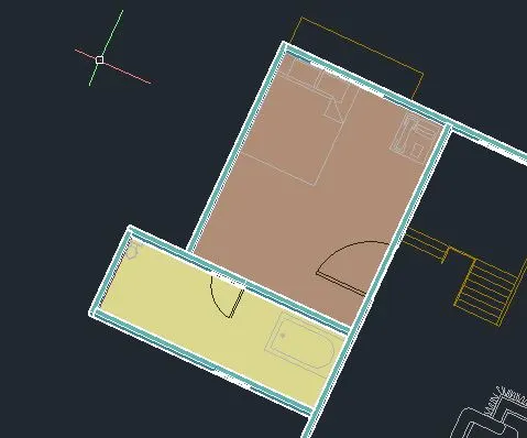
- Now we have to go to custome view and copy the whole plan and past it on top of the ground floor
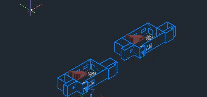
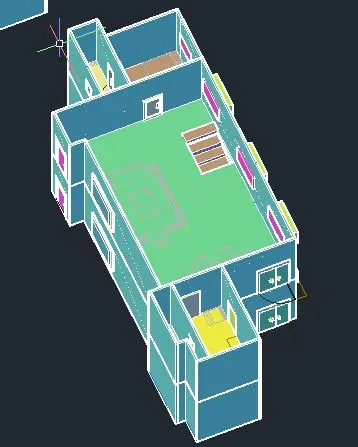
- For the first floor the opening is created for the staircase with the help of the Substract command
- In the command prompt type rec at the staircase top and then extrude it to the certain height
- Therfore with the help of substract command the opening is created
- In the command prompt type rec to draw the balcony layout and it is extruded to a particular height
- In the command prompt type cir draw the circle and extrude > trapper it to get the railings
- In the command prompt type polygon >4 sides > inside the circle > draw the rectangle and extrude > to get the railings
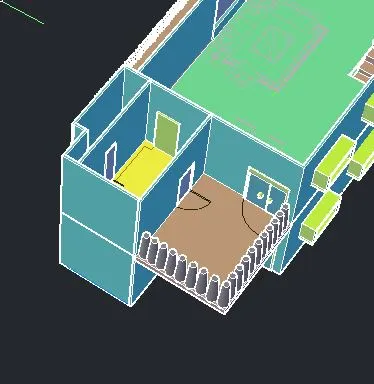
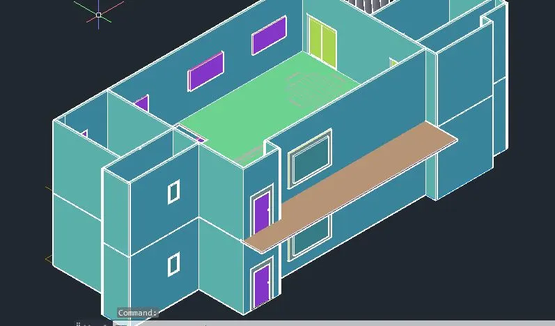
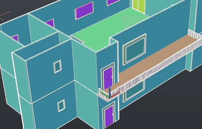
- In the command prompt type rec to draw the rectangle for the celling and exturde at 4"
- In the command prompt type Union to join the solids
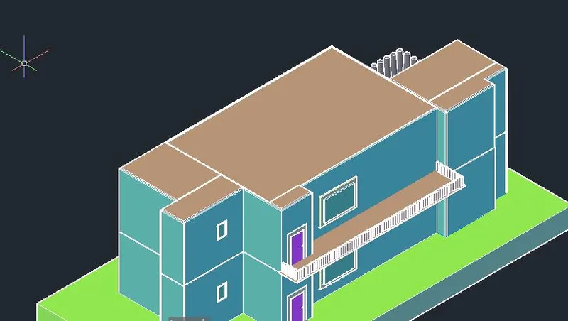
- With the help of box and extrude command the parapet wall is created with height of 3'-6"
- In the command prompt type Union to join all the parapet walls
- In the command prompt type rec and extrude it to a height to give the ground floor
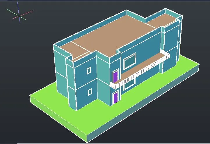
- After all this is done half our plan is complete
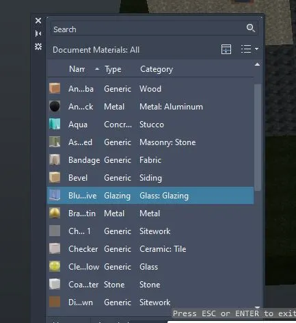
- Now in the ribbon bar > visualize > material browser ( to add the materials )
- for walls differnt stone materials are added
- For terrace masonary brick material is added
- for windows and doors glass materials are added
- All this can be seen in realistic view
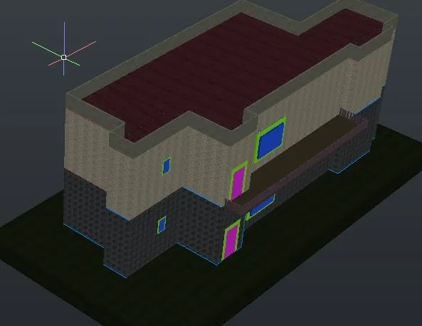
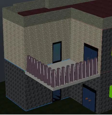
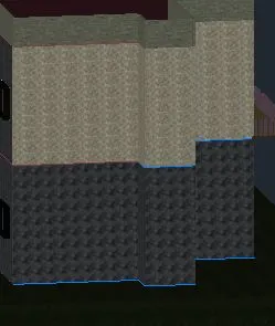
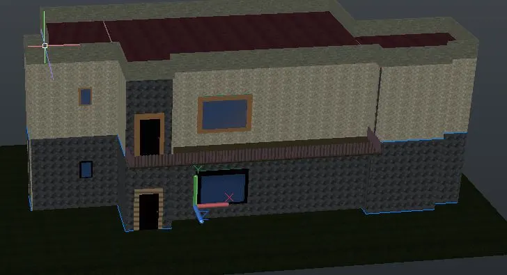
- The materials used in my projects are wood, Aluminum,stone ,glass,sitework , brick etc
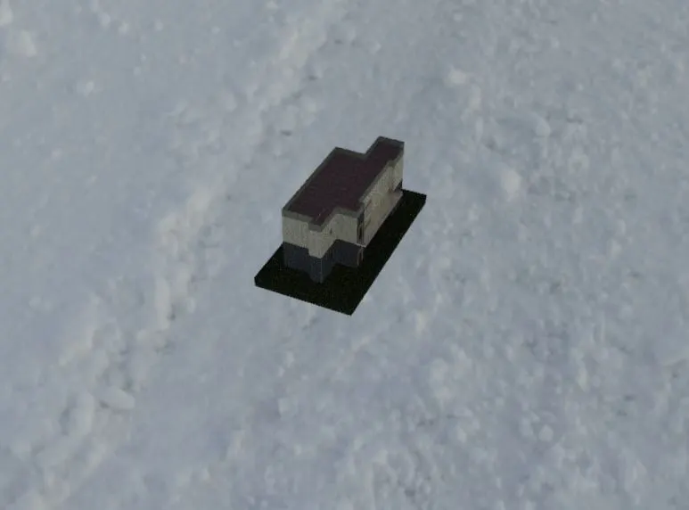
- After all this is done , Now we go to Ribbar tab > visualize > Render
- While doing render options we modify the sun setting , sky background, exposure setting .
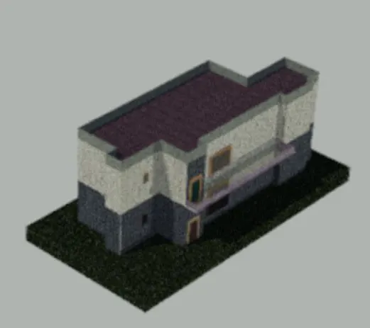
Final Result :