Creating 3D Isometric view of various structural elements in AutoCAD
Q.1
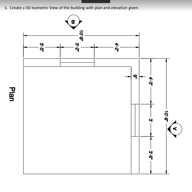
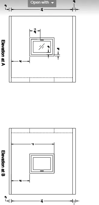
AIM :- To create a 3D isometric view of the given building plan and elevation
Introduction:-
- Isometric drawing is a 3D representation of an object such as buildings,bridges,building elements like footing,column,rooms
- Isometric view provide clear vision to engineer at site of ongoing projects
Command used:-
- Line command
- Rectangle command
- UCS command
- Dimlinear command
- Region command
- Extrude command
- Substract command
- Box command
- Units command
- Dimstyle command
- Box command
- 3d face command
- 3D orbit command
- dist command
- Solid edit command
- Union command
- Boundary command
- 3D mirror command
- Erase command
- Plan command
Procedure:-
Step 1:-
- Open autocad and set max limit and minimum limit on screen
- Now set units in inches and feet
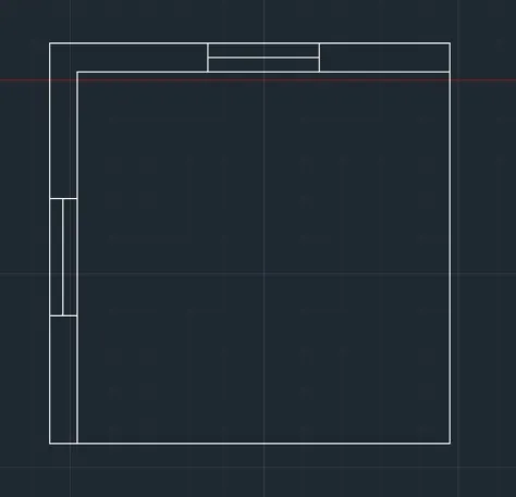
- draw rectangle by using rect. command
- next draw 2 windows of sizes of 3' x 9" and 9" x 3'-2"
Step 2:-
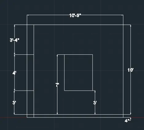
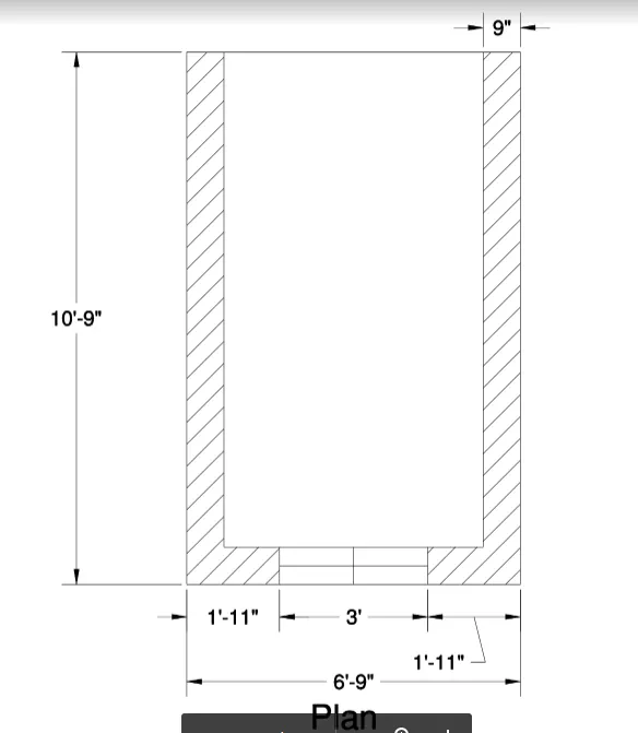
- Now draw the elevation of A and B as shown below fig.
- And put the dimensions using dimlinear command.
Step 3:-
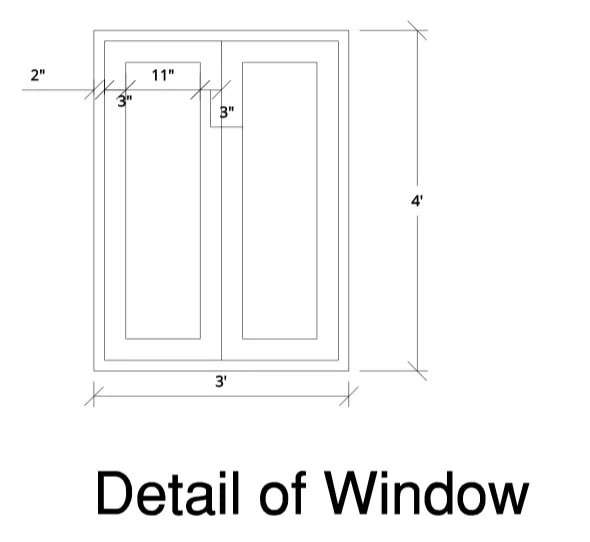
- Now draw the window of sizes 3' x 4' as shown
- Now draw this window and extrude using extrude command

Step 4 :-
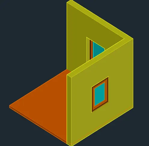
- Next we draw the walls using extrude command as shown in fig
- Now use the layers for providing the color to them
Step 5:-
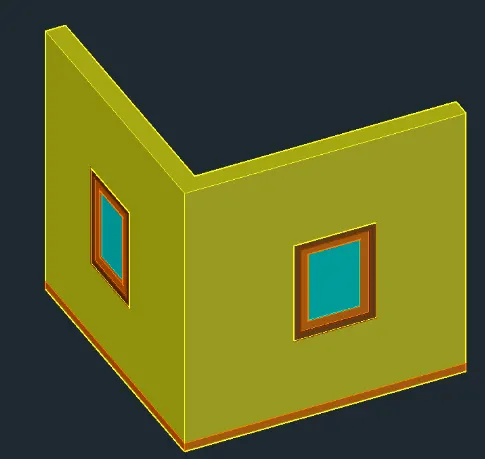
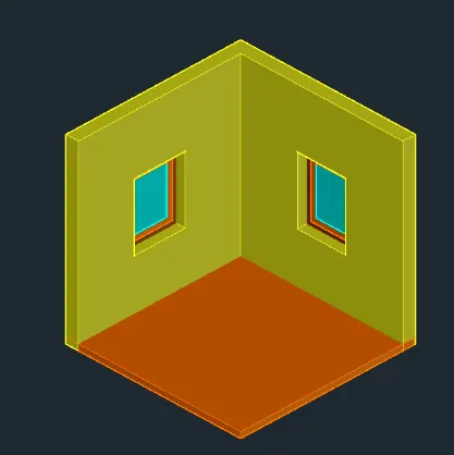
- Now use the 3D orbit command to see the diffrent views
Result:-
Q.2

AIM :-
To create a 3D isometric view of the given building plan and elevation
Introduction:-
- Isometric drawing is a 3D representation of an object such as buildings,bridges,building elements like footing,column,rooms
- Isometric view provide clear vision to engineer at site of ongoing projects
Command used:-
- Line command
- Rectangle command
- UCS command
- Dimlinear command
- Region command
- Extrude command
- Substract command
- Box command
- Units command
- Dimstyle command
- Box command
- 3d face command
- 3D orbit command
- dist command
- Solid edit command
- Union command
- Boundary command
- 3D mirror command
- Erase command
- Plan command
Procedure :-
Step 1:-
- Open autocad and set max limit and minimum limit on screen
- Now set units in inches and feet
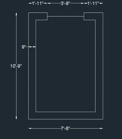
- draw rectangle by using rect. command
- next draw 2 windows of sizes of 3'2" x 9"
Step 2:-
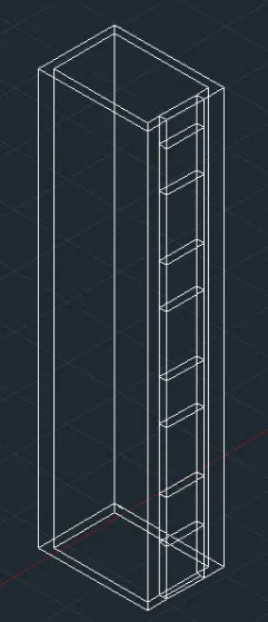
- We use region command and select the object and press enter
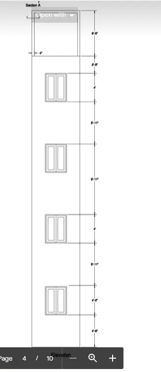
- next extrude the plan using height 40'10"
- next need to substract four window with distance 5'11" with window size of 3' x 4'
Step 3:-
- Now provide the layers for building as shown in figure
- And extrude the top surface of command

Step 4 :-
- Now we draw the window size 3'-2" X 4'
- next draw the window using the line command and extrude command.

Step 5:-
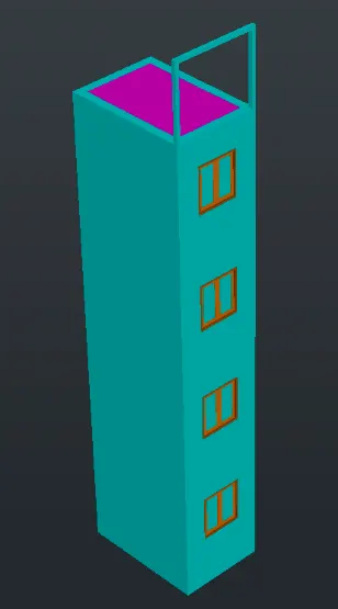
- Next we use 3D orbit command to view the elevation as shown
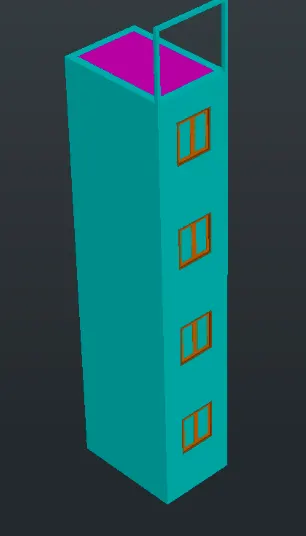
Final Result:-
Q.3

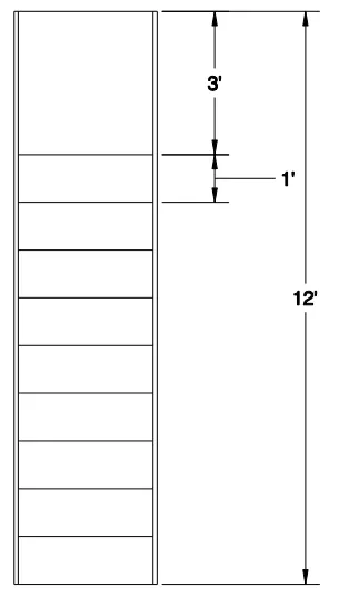
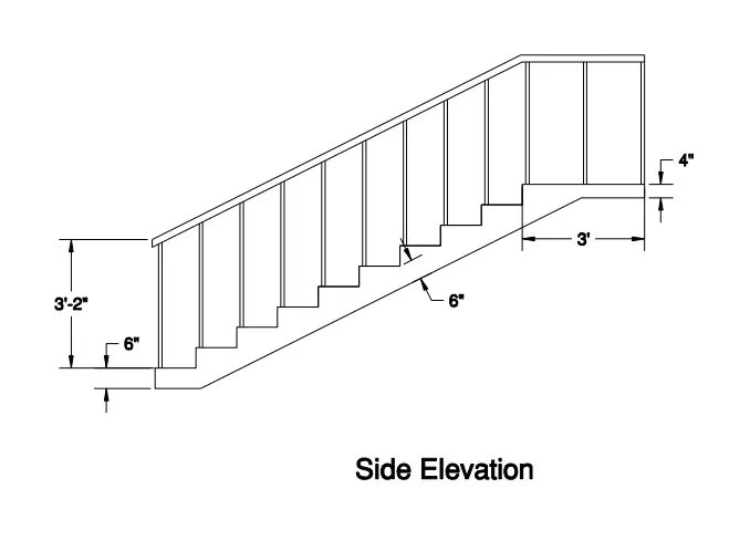
Aim:- To create the isometric 3D view of a stair with railing as shown in the plan and elevation
Introduction:-
- Isometric drawing is a 3D representation of an object such as buildings,bridges,building elements like footing,column,rooms
- Isometric view provide clear vision to engineer at site of ongoing projects
Command used:-
- Line command
- Rectangle command
- UCS command
- Dimlinear command
- Region command
- Extrude command
- Substract command
- Box command
- Units command
- Dimstyle command
- Box command
- 3d face command
- 3D orbit command
- dist command
- Solid edit command
- Union command
- Boundary command
- 3D mirror command
- Erase command
- Plan command
- Circle command
- Sweep command
Procedure :-
Step 1:-
- First open autocad and set max limit and minimum limit on screen
- Now set units in inches and feet
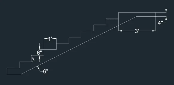
- we draw the stairs using line command
- Draw the stairs with the riser 6" and thread of 12" as shown
Step 2:-
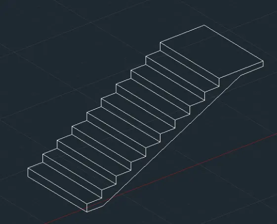
- Now we use 3D rotate command to rotate the above figure
- And now we will extrude the drawing in 3d view
Step 3:-
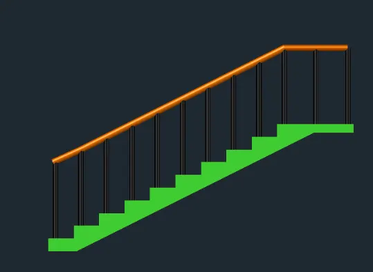
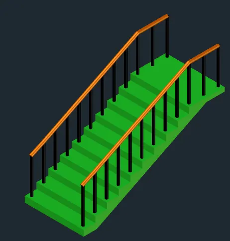
- Now we draw the railing using circle command and sweep command
- Next put the stair in 3d isometric view using 3dorbit as shown in drawing
Result:-
Q.4

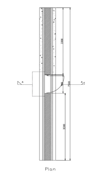
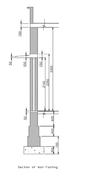
Aim:- To create the 3D view of a wall with spread footing and need to create a rendered view of the model with materials
Introduction:-
- Isometric drawing is a 3D representation of an object such as buildings,bridges,building elements like footing,column,rooms
- Isometric view provide clear vision to engineer at site of ongoing projects
Command used:-
- Line command
- Rectangle command
- UCS command
- Dimlinear command
- Region command
- Extrude command
- Substract command
- Box command
- Units command
- Dimstyle command
- Box command
- 3d face command
- 3D orbit command
- dist command
- Solid edit command
- Union command
- Boundary command
- 3D mirror command
- Erase command
- Plan command
- Circle command
- Sweep command
Procedure :-
Step 1:-
- First open autocad and set max limit and minimum limit on screen
- Now set units in decimal
- Next we have draw the plan of wall with spread footing wuth given dimension as shown below
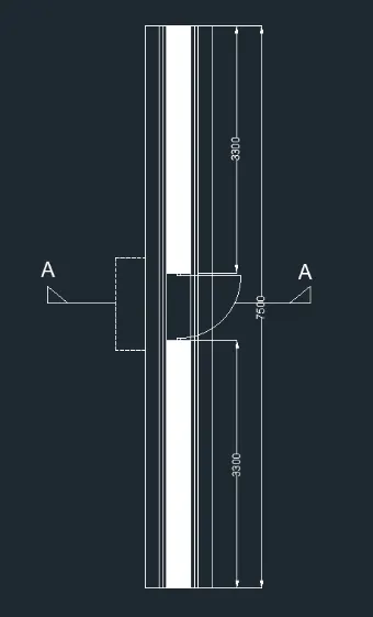
Step 2:-
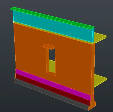
- Next we draw the 3d isoetric view of the wall with spread footing using extrude command
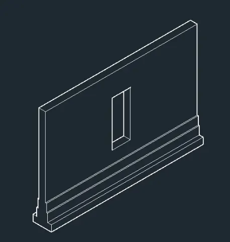
Step 3:-
- Next provide the layers for the wall with spread footing with diffrent color
Step 4:-
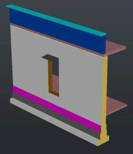
- now we will assign the material for wall and footing as shown below
Step 6:-
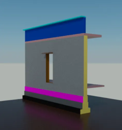
- Now we select the render option and then changes to the rendering view as shown below
Result: