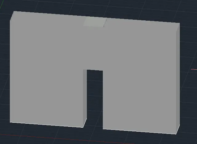
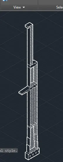
Creating 3D Isometric view of various structural elements in AutoCAD
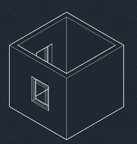
1.
Aim:
To draw the 3d isometric view using autocadd
Procedure:
Step 1
Rectangular specific point at 0
Rectangular specific point at dimension
Rectangular specific point at 10'9" x 10'9"
Step 2
offset specific point at 9"
Step 3
Window
Rectangular speific point at 3' x 4'
offset specific point at 3"
offset specific point at 4"
Step 4
Window
Rectangular specific point at 3'2" x 4'
offset specific point at 3"
offset specific point at 4"
Step 5
use command extrude
select the object
built the object at 10'
Step 6
draw the rectangular
built the object 3'
built the object from the top at 3'
Step 7
move the window
select the basepoint
drop the window
Step 8
select the hidden option
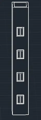
2.
Aim:
To draw the 3d isometric view using autocadd
Procedure:
Step 1
line specific point at 0
line specific point at 10'9"
line specific point at 6'9"
line specific point at 10'9"
Step 2
offset specific point at 9"
line are join the object
Step 3
offset specific point at 1'11"
offset specific point at 3'
Step 4
use command extrude
select the object
extrude the line at 40'8"
Step 5
draw the rectangular
copy the object
Step 6
copy the object at 4'8"
copy the object at 4'
copy the object at 5'11"
copy the object at 4'
copy the object at 5'11"
copy the object at 4'
copy the object at 5'11"
copy the object at 4'
copy the object at 2'5"
Step 7
copy the window to be paste
Step 8
select the hidden option
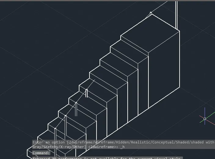
3.
Aim:
To draw the 3d isometric view using autocadd
Procedure:
Step 1
Rectangular specific point at 0
Rectangular specific point at dimension
Rectangular specific point at 3'2" x 12'
Step 2
offset specific point at 3'
offset specific point at 1'
offset specific point at 1'
offset specific point at 1'
offset specific point at 1'
offset specific point at 1'
offset specific point at 1'
offset specific point at 1'
offset specific point at 1'
offset specific point at 1'
Step 3
use command extrude
extrude the line at 6"
extrude the next line at 12"
extrude the next line at 18"
extrude the next line at 24"
extrude the next line at 30"
extrude the next line at 36"
extrude the next line at 42"
extrude the next line at 48"
extrude the next line at 54"
Step 4
draw the circle
extrude the line at 3'2"
Step 5
copy the circle at specific step
Step 6
join the line
Step 7
select the hidden option
4.
Aim:
To draw the 3d isometric view using autocadd
Procedure:
Step 1
Rectangular specific point at 0
Rectangular specific point at dimension
Rectangular specific point at 7500 x 1000
Step 2
Rectangular specific point at 7500 x 250
Step 3
offset specific point at 3300
offset specific point at 900
Step 4
use command extrude
extrude the line at 3000
Step 5
draw the rectangular
copy the object
built the object
Step 6
Rectangular specific point at 0
Rectangular specific point at dimension
Rectangular specific point at 700 x 300
Step 7
line specific point at 0
line specific point at 400
line specific point at 20
line specific point at 400
line specific point at 20
line specific point at 600
line specific point at 210
Step 8
mirror the object
Step 9
offset specific point at 50
Step 10
line specific point at 0
line specific point at 2100
line specific point at 420
line specific point at closed
Step 11
offset specific point at 150
line specific point at extend
Step 12
line specific point at 50
line specific point at closed
Step 13
line specific point at 0
line specific point at 1050
line specific point at 420
line specific point at closed
Step 14
offset specific point at 150
line specific point at 1000
Step 15
use command extrude
select the object
extrude the line at 500
Step 16
select the hidden option