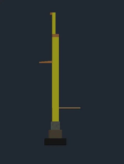
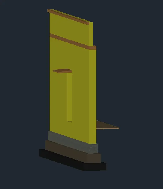
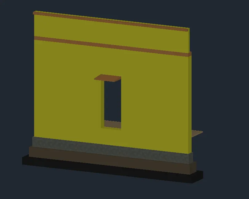
Creating 3D Isometric view of various structural elements in AutoCAD
(1) 3D ISOMETRIC VIEW OF THE BUILDING
- Open a new drawing file.
- Set the units to engineering and set the limits.
- Select the convenient zoom option.
- Draw the 2D wireframe plan of the building.
- Using BO command, convert portions in the plan as regions.
- Now, start to develop 3D model from this 2D wireframe model.
- From the view cube, adjust the view to work with.
- Extrude the wall portions to a height of 10'4". This height includes the thickness of the floor also.
- Now, extrude the window opening up to sill level, ie, extrude to 3' height.
- Now, at the roof level, in between the wall gap, draw rectangles and extrude it down to a height of 3'4".
- Go for the shaded option and makes the wall union.
- Now, draw the roof level at the top of the wall. For that draw rectangles and extrude it to a height of 6".
- Now, at the bottom of the wall, draw a rectangle and extrude it to a height of 4", to make the floor thickness.
- Then start to draw the windows.
Window in elevation B;
- Draw a rectangle of size (3'2" x 4').
- Offset it by 3" to create a rectangle inside and offset this new rectangle by 4".
- Extrude the two rectangles to a distance of -7" and substract the smaller area from the bigger one, to create the frame of window.
- Similarly create the inner frame with thickness 4".
- Draw a rectangle of size (2' x 2'10") and extrude it to a distance of 0.6" to create glass for window.
- Arrange the frames and glass panel to create the window in elevation B and place it in the window opening.
Similarly, create the window in elevation A and place it in the window opening in the wall.
- Now, assign material properties to wall, roof and floor.
- The 3D isometric view of the building is ready and select the realistic option for visual style.
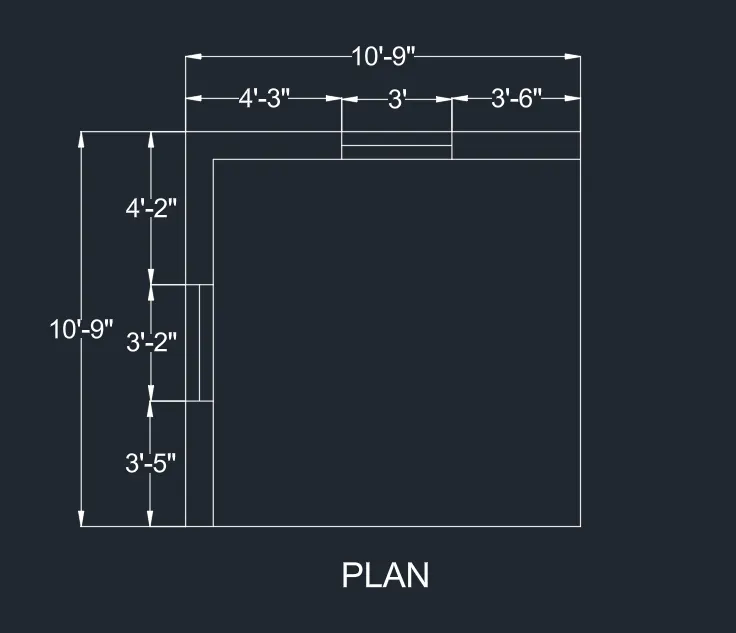
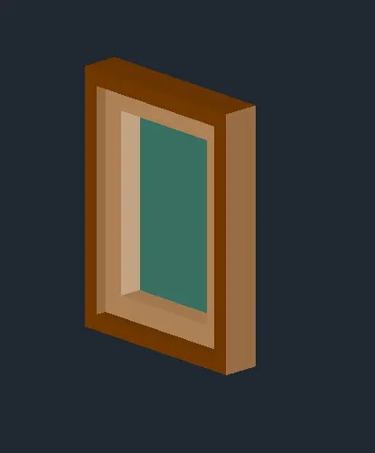
Window in elevation A
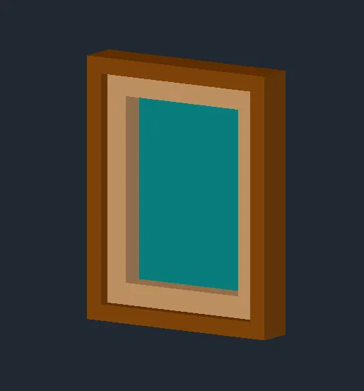
Window in elevation B
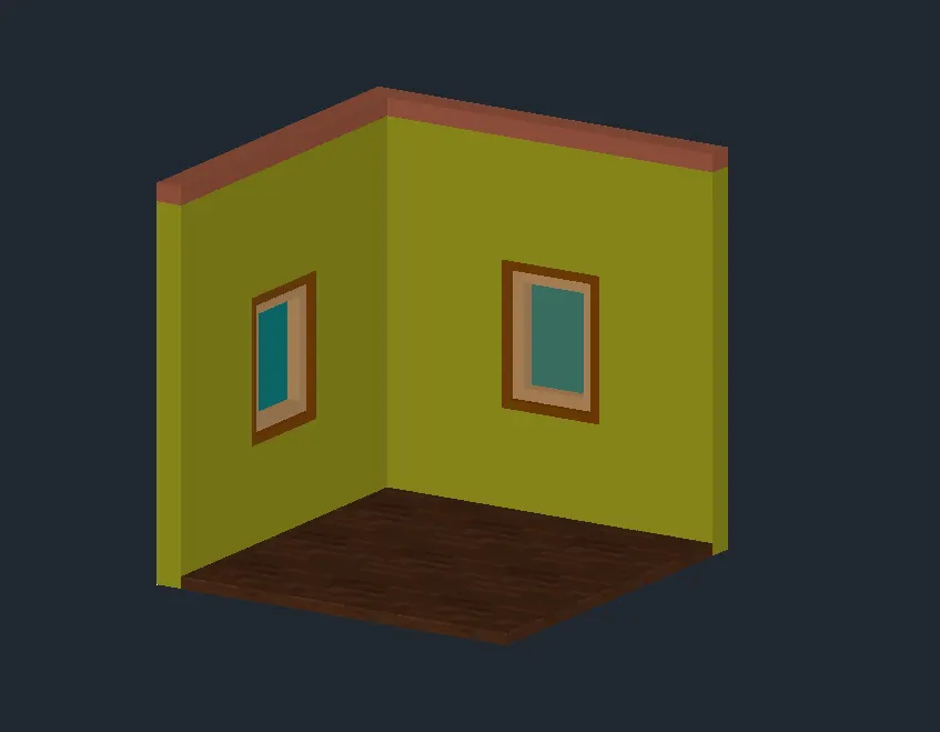
(2) 3D VIEW OF BUILDING FACADE
- Open a new drawing file.
- Set the units to engineering and set the limits.
- Select the convenient zoom option.
- Draw the 2D wireframe plan of the building facade.
- Using BO command, convert portions in the plan as regions.
- Now, start to develop 3D model from this 2D wireframe model.
- From the view cube, adjust the view to work with.
- Presspull the wall portions and window portion to a height of 4'6". This is up to sill level of the ground floor.
- Presspull the wall portion to a height of 121" and at the top of the wall, draw a rectangle in between the gap.
- Presspull this rectangle downwards to a distance of 71".
- Presspull the wall height to 4'.
- Again, in between the gap of the walls, draw a rectangle and presspull it to a height of 71". Also pressfull the wall portion to this height.
- Now, presspul the wall portion to a height of 119" and in between the gap of the walls, draw a rectangle and presspull it down to a height of 71".
- Now presspull the wall height to a distance of 77" and in between the gap of the walls, draw a rectangle and presspull it down to a height of 29".
- To draw the section at the top, draw an opening with dimensions as given using lines at the top portion and join it so that it becomes a closed region, and extrude it backwards to a distance of 10'9".
- Union the wall portions.
- Assign wall paint to walls from the material browser.
- Now , start to draw the window frames and make the windows to fit into the openings in wall.
Ground floor window;
- Set the workspace to wireframe.
- Draw the 2D model of the window.
- Set the view from the view cube.
- Create the window frames and panels as per the given dimensions using commands EXTRUDE and SUBTRACT.
- Arrange the frames and panels to create the windows and assign material properties.
- Then place it in the openings.
- Select the realistic visual style.
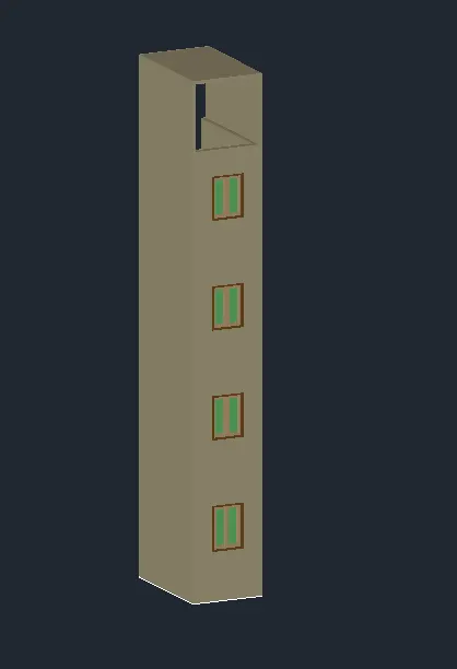
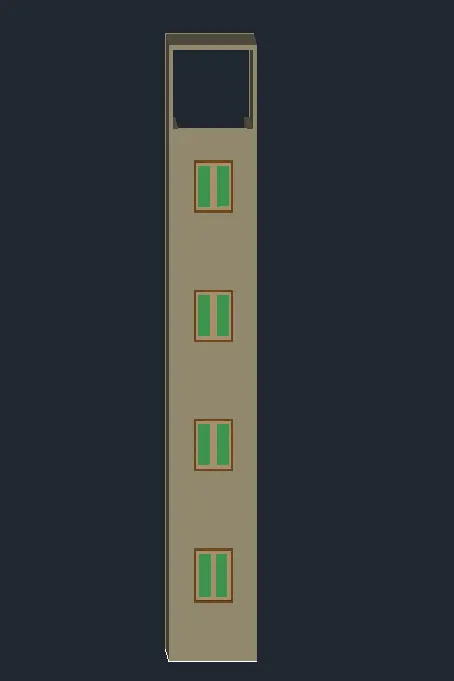
RESULT:
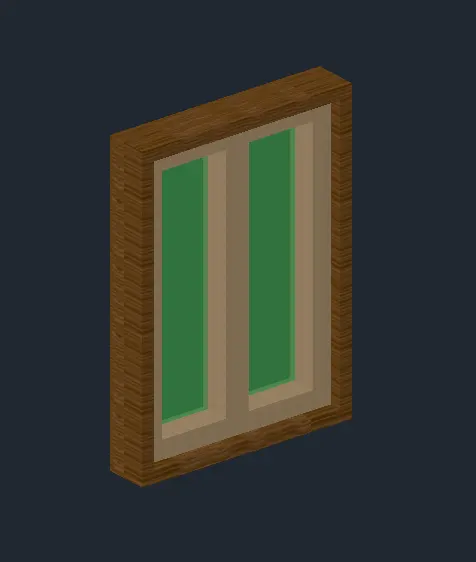
GROUND FLOOR WINDOW - (3' x 4'2")
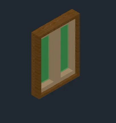
FIRST, SECOND AND THIRD FLOOR WINDOW - (3' x 4')
(3) 3D ISOMETRIC VIEW OF STAIR
- Open a new drawing file.
- Set the units to engineering and set the limits.
- Select the convenient zoom option.
- Draw the 2D wireframe model of the stair side elevation using lines.
- Set the view from view cube and rotate the 2D step using 3DROTATE.
- Extrude it horizontally to a distance of 2'9".
- To draw the railings, draw a circle on the step, extrude it to a height of 2'9" and copy this to all the steps.
- Now, connect the top center of all cylinders using lines and convert these lines in to polyline.
- Draw a circle and make it sweep through the polyline.
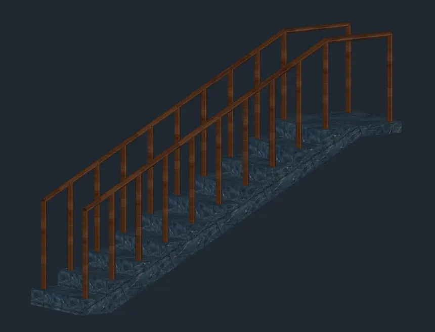
- Select the realistic visual style and assign material properties.
RESULT:
(4) 3D VIEW OF WALL WITH SPREAD FOOTING
- Open a new drawing file.
- Set the units to decimal and set the limits.
- Select the convenient zoom option.
- For convenience divide the footing as three parts; the door opening portion and the portions on either side of the door opening.
- Set the view from the view cube.
- Draw rectangles of sizes, (1000 x 3300)mm, (600 x 3100)mm, (400 x 3000)mm and (300 x 2950)mm.
- Now, move the three smaller rectangles to a height of 700mm, 1400mm and 2000mm from the right end portion of the big rectangle.
- Extrude the big rectangle to a height of 300mm and the subsequent rectangles to heights of -400mm, -400mm and -600mm.
- Do the same to the other portion of footing.
- At the top of the footing, in between the gap, draw a rectangle.
- Pressfull the faces of the footing to a horizontal distance of 900mm to fill the gap.
- Extrude the wall portion on either side of the door opening to a height of 2100mm.
- Draw a rectangle at the top of the wall and extrude it to a height of 150mm so as to create the lintel.
- Draw another rectangle at the top of the lintel and extrude to a height of 1050mm to reach the roof level.
- Draw a rectangle on top of the wall and extrude it to a height of 150mm to provide the roof slab thickness.
- Now, draw a rectangle on top of the roof slab, with half the width of the wall, and extrude it to a height of 1000mm so as to make the parapet wall.
- Create a coping with projection of 100mm at the top of the parapet wall.
- Create a sunshade on above the door, with projection of 600mm and the thickness as mentioned in the section.
- Make the wall portions union.
- Also, at the plinth level, provide the floor with thickness of 50mm.
- Set the visual style to realistic and assign material properties to different components.
- After assigning material properties, go for different view using the command 3DORBIT.
RESULT: