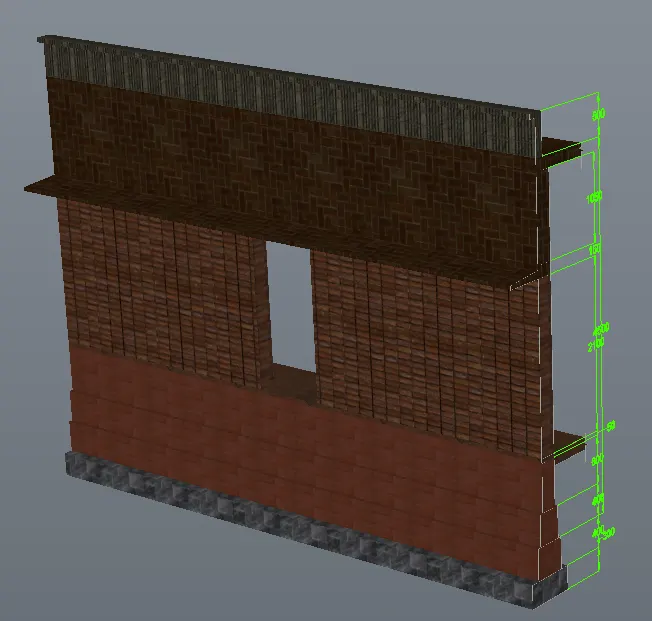
Creating 3D Isometric view of various structural elements in AutoCAD
AIM:- To create a 3D isometric view of the given building with plan and elevation
INTRODUCTION :-
. An isometric drawing is a 3D representing of an object , room , building or design on a 2D surrface .
. One of the defining characteristics of an isometric drawing ,compared to other types of 3D representing , is that the final
image is not disorted .
. In an isometric drawing the object appears as if it is being viwed from above from one corner , with the axes being set
out from this corner point .
. Isometric drawing begin with one vertical line along which two point are defined .
. Any lines set out from these point should be constructed at an angle of 30 degree .
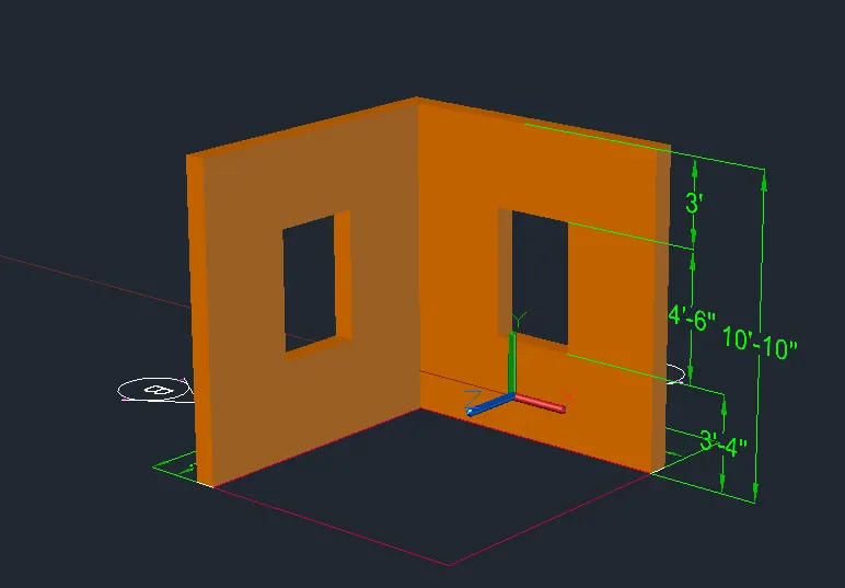
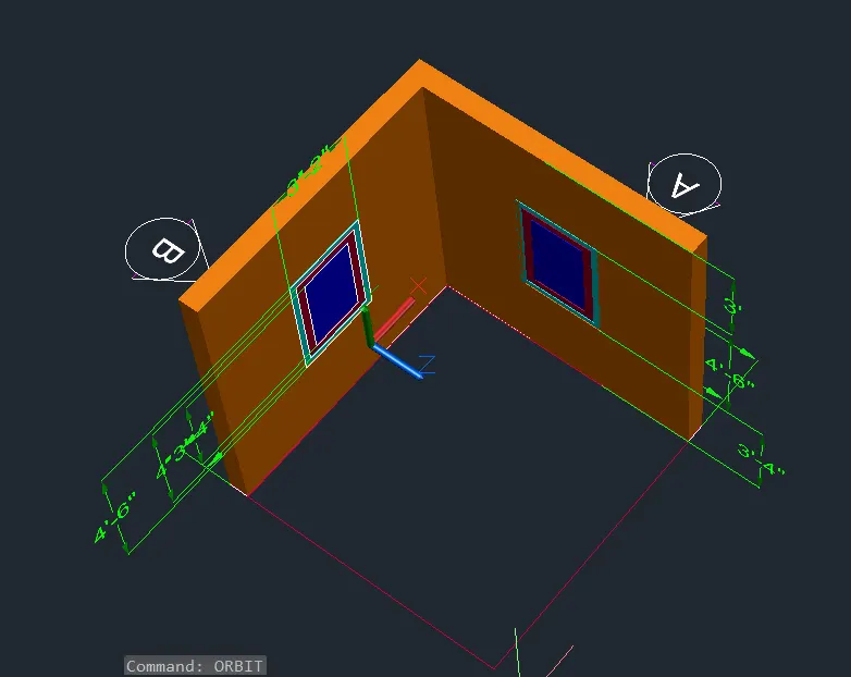
. A plan view of wall of two elevation view of window on both sides are given with details regarding the frame dimenssion
, mullion dimenssion and handle height. the thickness of bottom floor and top roof are also given as 4" and 6" respestive.
the height of floor is given as 10' . height of window from the floor is 3' .
COMMAND USED :-
. Line command
. Rectangle command
. UCS command
. Dimlinear command
. Extrude command
. Subtract command
. Box command
. Units command
. Dimstyle command
. 3Dface command
. 3Dorbit command
. Hide command
. Explode command
. Move command
. Copy command
. Dist command
. Solidedit command
. Union command
. Boundary command
. 3D mirror command
. 3D rotate command
. Erase command
. Plan command
PROCEDURE :-
. Open autocad
. In startup setting start from scratch select imperial ( feet and inches )
. Open grid and snap settigs
. Change snap and grid spacing to 1'
. Change major line every grid line to 10
. Turnoff adaptive grid
. Type ' UN ' in command box and press enter
. Change units , type to decimal and precision to 1'1/16" and insertion scale to inches
. Change the workplace setting of Autocad from drafting and annotation to 3D modellig
. Open layers properties and create new layers to create new layer
. Layer as follows
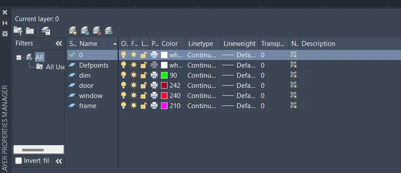
. Change the current layer to 3D wall
. Create a rectangle of dimenssion 10'9"x10'9" at any point on the screen
. offset the rectangle to inside a distance of 9" as wall thickness
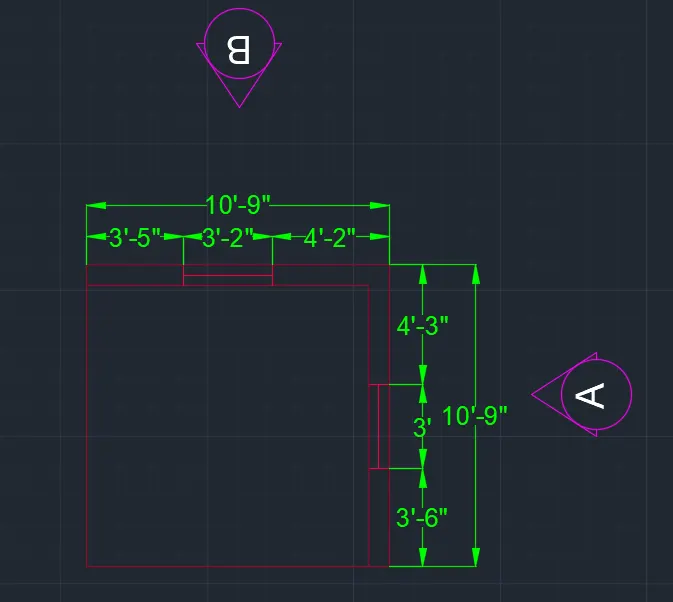
. Delete the left and bottom lines and extend them to the edge as shown in figure
. Change the current layer to 3D window frame
. Draw the window with dimenssion 3'2" at top and 3' on right side as shown in figure
. Change the view to 3D by clicking on home button of view cube
. Set UCS as world
. Ceate the boudary for the walls using BO command
. Extrude the boundaries created to total height of 10'10"
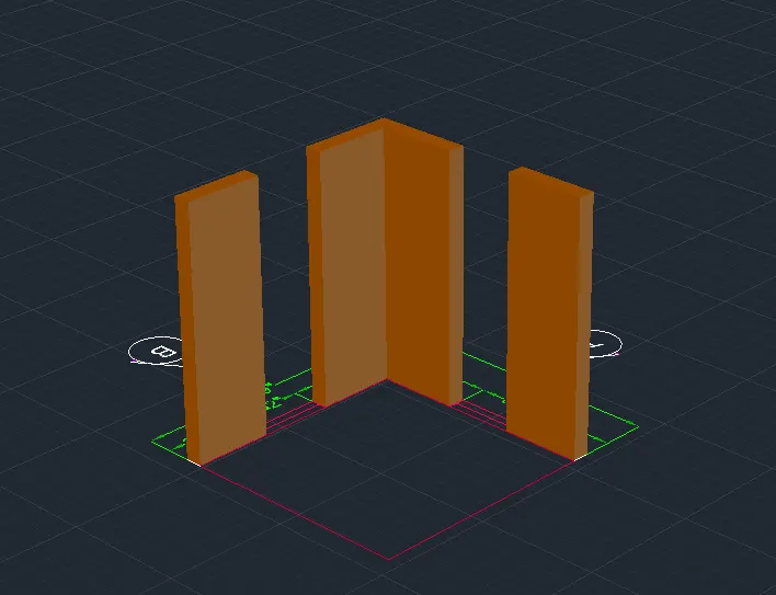
. Select all the new wall and use group command to group then together
. Draw rectangles at both windows and change them to boudaries using boundary command .
. Extrude both rectnagle drwan to height of 3'4" as shown in the figure
. Draw rectangle at top of both window openning and change them to boudaries using boundary command
. Type UCS and click on face and select the face having 3' wide window
. Draw a rectangle from bottom part of window with dimenssion @3'2",4'
. Change the ucs back to world
. Group all the wall componanet together
. Change the current layer to 3D window frame
. Type UCS and click on face and selecting the face having 3' wide window
. Draw a rectangle of dimenssion @3',4'
. Offset the rectangle to inside to distance of 3"
. Offset the offset rectangle to inside to distnace 4"
. Click inside the window frame area and press enter
. Start SUBTRACT command
. Select the bigger region and then select the smaller region to sutract them
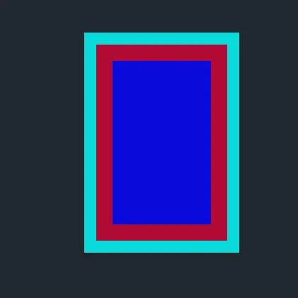
. Follow the same procedure for all the three boxes as shoen in fig
. Changes the current layer to 3D window mulion
. Start the boundary command and click on pick points
. clicks inside the window mulion area and press enter
. Start SUBTRACT command
. Select the bigger region and then select the smaller region to sutract them
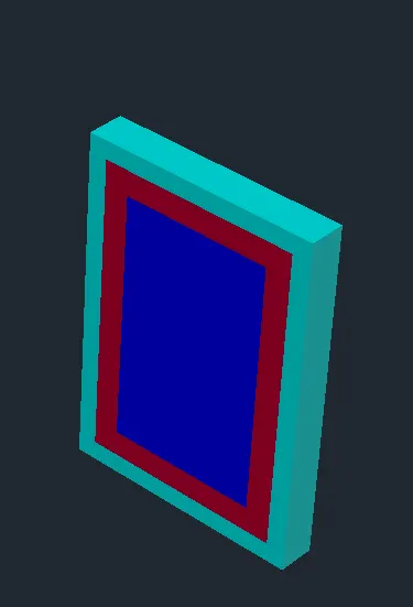
. Change the current layer to 3D window glass
. Start the boudary command and click on pick points
. Click inside the window glass area and press enter
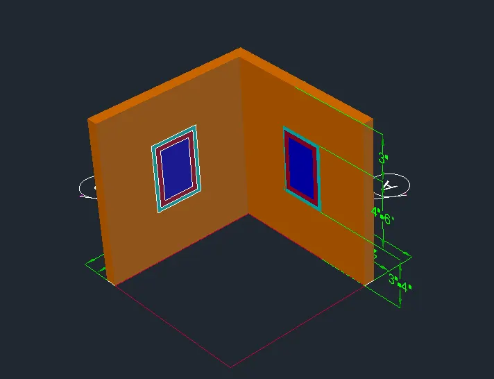
. All the layers are extrude to give window project loos as shown in fig
. Window at elevtion B
. Type UCS and click on face and select the face having 3'2" wide window
. Draw a rectangle of dimenssion @ 3'2",4'
. Offset the rectagle to inside to distnace of 3"
. offset the offset rectangle to inside to distance 4"
. Change the layers for all the boxes respectivly
. start the boundary command and click on pick points
. Click inside the window frame area and press enter
. Start SUBTRACT command
. Select the bigger region and then select the smaller region to subtract them
. Start the boudary the window mulion area and press enter
. All the layers are extrude to give window projection looks as shown in fig
. Next we use the 3Dorbit command see the different view of the given fig
. Place the window drawn in the elevation
RESULT :-
The given 3d isometric view of the building with plan and elevation is drawn successfully in the AutoCAD in details
manner .
AIM 2 :- To draw the 3D building facade as given in the plan and elevation
INTRODUCTION : -
. An isometric drawing is a 3D representation of an objetct , room ,building , or design on a 2D suraface
. One of the defining characteristics of an isometric drawing , compared to other types of 3D representation , is that the
final image is not disorted
. This is due to the fact that the for shortning of the axis is equal
. In an isometric drawing , the object appears as if it is being view from above from one corner with the axes being set
out from this corner point
. A plan view of wall and two elevation view one is of a window details and second is of floor level elevation are given
and they are to be converted into 3d model . one window openning on front side is given with details regarding the
frame dimenssion two mullion dimenssion . the height of floor is given as 9'11" four floor building with similar
dimenssion is made in 3D view . height of window from the floor level of each floor is given as 4'6"
COMMAND USED :-
. Line command
. Rectangle command
. UCS command
. Dimlinear command
. Extrude command
. Subtract command
. Box command
. Units command
. Dimstyle command
. 3Dface command
. 3Dorbit command
. Hide command
. Explode command
. Move command
. Copy command
. Dist command
. Solidedit command
. Union command
. Boundary command
. 3D mirror command
. 3D rotate command
. Erase command
. Plan command
IN.TRODUCTION :-
. Open Autocad
. In startup settings start from scratch selelct imperial (feet and inches )
. Open grid and snap settings
. Change snap and grid spacing to 1'
. Change major line evey grid line to 10
. Turnoff adaptive grid
. type 'UN' in command box and press enter
. Change unit type to decimal and precision to 1'1/16" and insertion scale to inches
. Change the workspace settings of Autocad from drafting and annotation to 3D modelling
. Open layer properties and create new layer by clicking on new layer or right click on any
. Layer are created as follows
. Creating 2D plan view
. Create a rectangle of dimension 6'9"x10'9" at any point on the screen
. offset the rectangle to inside to distance of 9" as wall thickness
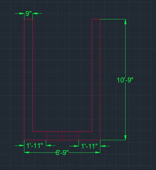
. Explode the rectangle draw
. Delete the top line and extend them to the edge
. Change the current layer 3D window frame
. Create the window openning of dimenssion 3' wide as shown in fig
. Add dimenssion are drawn using dimenssion layer
. Creating 3D view
. Change the view to 3d by clicking on home button of view cube
. Set UCS as world
. Set the view style control as REALISTIC
. Create the boundaries for the wall using BO command
. Extrude the boundaries created to total height of 40'10"
. selelct all the wall and use group command to group then together
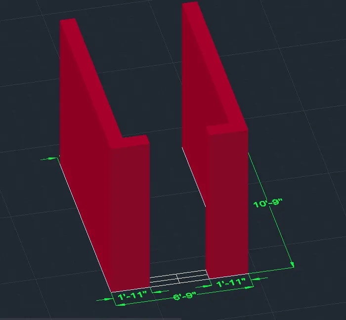
. Delete the window line
. Create a boundary region over the window line
. Extrude the boundary to height of 4'6"
. Draw a rectangle on top of the window openning using rectangle command
. Change the rectangle into region
. Extrude the region to distance of 1'3" to below and then window openning is created as shown in fig
. Creating elevation window
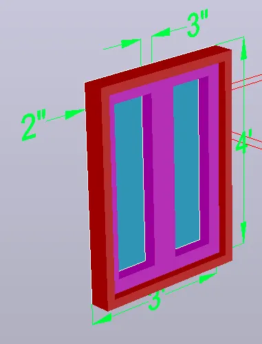
. 4' Wide window
. change the current layer to 3D window frame
. Type UCS and click on face and select the face having 3' wide window
. Offset the rectangle to inside to distance of 2"
. Offset the rectangle to inside to distance 3"
. Trim all the unnecessary edge
. Start the boundary command and click on pick points
. Click inside the window frame area and press enter
. Start SUBSTRACT command
. select the bigger region and then select the smaller region to subtract them
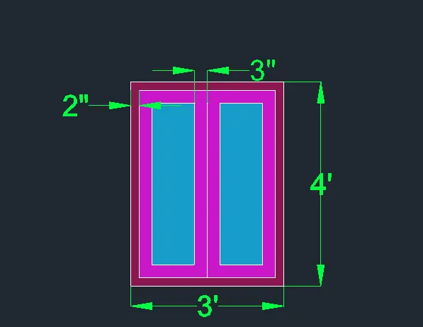
. Change the current layer to 3D window mulion
. Start the boudary command and click on pick points
. Click inside the window mulion area and press enter
. Start SUBTRACT command
. select the bigger region and then select the smaller glass region to subtract it
. change the current layer to 3D window glass
. Start the boundary command and click on pick points
. Click inside the window glass area and press enter
. All the layers are extrude to give window projection look as shown in fig
. Change the view of window and place them the plan view
. Place the window drawn in front view plan already shown
. Create the top of the drawing using 4" wall with hight 6'5" from top
. create a bounadary for all the wall
. Extrude the boundary to 9" as shown in fig
. Next we use 3rdorbit command to view the front elevation as shown in below figure
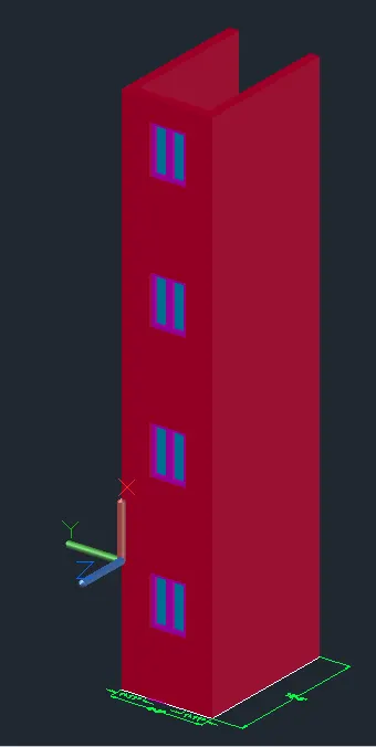
. Now the building putting facade in the 3d isometric view using the 3rd orbit command as shown in fig
RESULT :-
The given 3d isometric view of the building facde is drown successfully inthe Autocad in detail manner
AIM 3 :- To create the isometric 3d view of a stair with railing as shown in the plan and elevation
INTRODUCTION : -
. An isometric drawing is a 3d representation of an object , room , biulding , stair , or design on a 2D surface
. One of the defining characteristics of an isometric drawing compared to other types of 3D representation ,is that
the final image is not disorted
. This is due to the fact that foreshortning of the axes is equal
. in an isometric drawing the object appears as if it is being viewed from above from one corner with the axes being set
out fromt his corner point
. Isometric drawing begins with one vertical line aling which two pionts defined
. Dimenssion of vertical rails is 1" diameter
. Dimenssion of hand rails is 2" diameter
COMMAND USED :-
. Line command
. Rectangle command
. UCS command
. Dimlinear command
. Extrude command
. Subtract command
. Box command
. Units command
. Dimstyle command
. 3Dface command
. 3Dorbit command
. Hide command
. Explode command
. Move command
. Copy command
. Dist command
. Solidedit command
. Union command
. Boundary command
. 3D mirror command
. 3D rotate command
. Erase command
. Plan command
PROCEDURE :-
. Open AutoCAD
. In startup settings start from scratch selelct imperial
. Open grid and snap settings
. Change snap and grid spacing to 1'
. Change major line every grid line to 10
. Turnoff adaptive grid
. Type 'UN' in command box and press eneter
. Change units type to decimal and precision to 1'1/16" and insertion scale to inches
. Change the workspace settings of AutoCAD from drafting and annotation to 3D modelling
. Open layer properties and create new layer by clicking on new layer or right click on any layer and select new layer
to create new layer
. layer are created as follows
. Change the current layer to stairs
. Draw a rectngle of dimension 3'X12'
. Explode the rectangle
. Offset the side edge to inside to a distance of 1"
. Offset the bottom edge to upside 12 times to distance of 1' as shown in fig
. Change the view to 3d by clicking on home button of view cube and change the view to right view
. Set UCS as right
. Start line command and draw a vertical line of length 6"
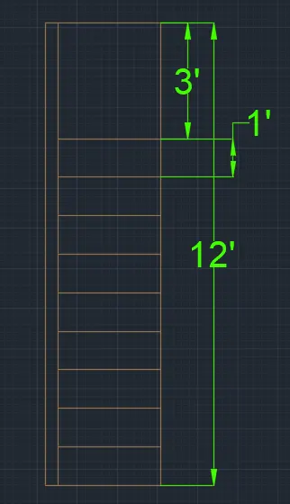
. Repeat the same process for 12 times to draw 12 steps
. After reaching 12 steps draw a landing of length of 3'
. Draw line of 1' at the bottom steps
. Draw a line of 6 " at the top right edge of landing
. Draw a line of 1'6" backwards
. draw a slab joinnig the lines
. Change the view to 3d by clicking on home button of view cube
. Set UCS as world
. Set the view style control as realstics
. create a region from the side view of the stairs
. Extrude the side view to a distance of 3' as shown in fig
. Hand rails
. Change the circle into a region
. Extrude the region to a height of 3' as shown in fig

. Change the current layers to stairs handrails stand
. Draw a handrails stand at bottom with dimenssion 2" and extrude as shown in figure
. copy the same to the other side as shown in fig
. Change the current layer to stair handrails
. draw a polylins connecting all the top edge of hand rails
. Change the UCS to front
. Draw a circle of a diameter 2" on top of the first hand rails
. Create a region of the circle drawn
. Start sweep command
. selelct the circle as object to sweep
. selelct the circle as object to sweep
. copy the same to the other side
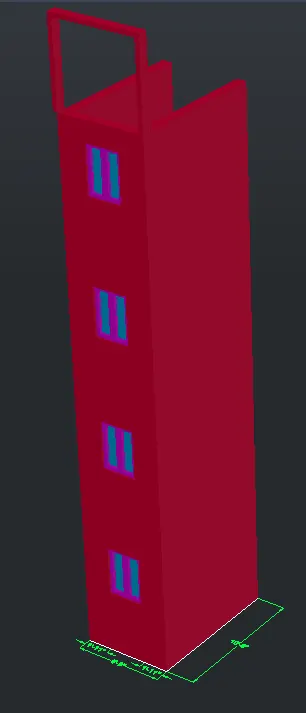
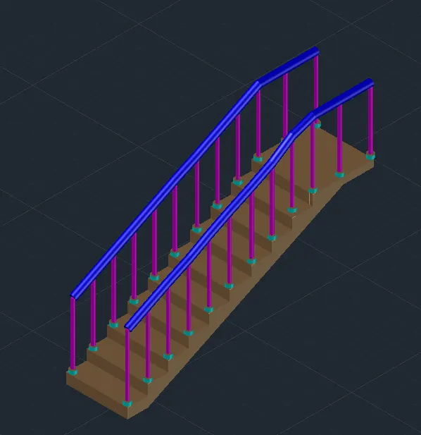
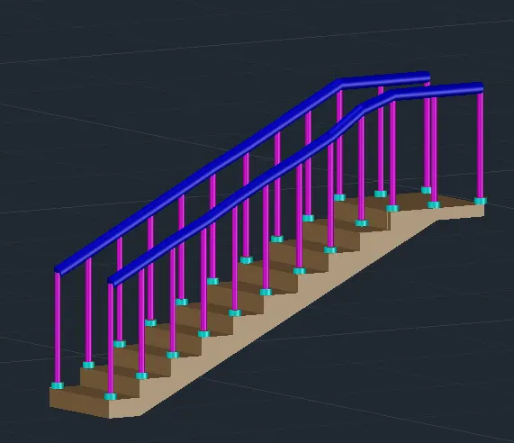
. now put the stairs in the 3d isometric view using the 3d orbit command as shown in fig
RESULT :-
The given 3d isometric view of the stairs is drawn sucessfully in the autocad in detailed manner
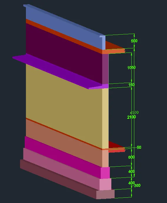
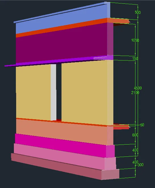
AIM :- To create the 3d view of a wall with spread footing and need to create a rendered view of the model
with material
INTRODUCTION :-
. An isometric drawing is a 3d representation of an object room building stairs or design on a 2d surface
. one of the definning characteristics of an isometric drawing , compared to other types of 3d representation is that the
final image is not disorted
. This is due to the fact that the foreshortining of the axis is equal
. In an isometric drawing the object apperars as if it is being viewed from above from one corner with the axes being set
out from this corner point
. Thickness of level 1 of footing is same as wall thickness i.e . 230mm
. Coping thickness of level 2 is offset of 50 mm than the thickness of wall
. Tahickness of level 3 is offset of 50 mm than the thicness of level 2
. Thickness of level 4 is offset of 120 mm than the thickness of level 3
PROCEDURE :-
. Open AutoCAD
. In startup setting from scratch metric
. open grid and snap settings
. Change snap and grid spacing to 100
. Change major line every grid line to 10
. Turnoff adaptive grid
. Type UN in command box and press enter
. Change units type to decimal and precision to 0.00 and insertion scale to inches
. Change the workspace setting of AutoCAD from drafting and annotation to 3D modelling
. Creating layers
. Open layer properties and create new layers by clicking on new layer or right click on any layer ans selelct new layer
to create new layer
. layer are creted as follows
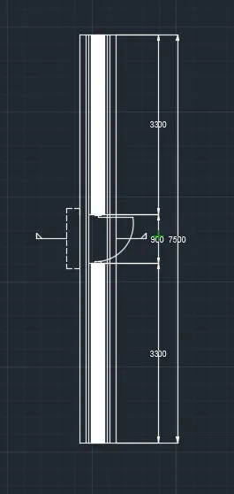
. Creating 2D plan view of wall with spread footing
. Change the current layer to wall
. draw the current layer to wall
. draw a rectangle of dimenssion 670 x 7500
. Offset the rectangle to inside a distance of 120 mm
. Offeset the offset rectnagle inside to distance of 50 mm the twice
. Explode all the offset rectangle
. Delete the top and button edge of the explode rectangle
. Extend all the rectangle to top and button edge of outer rectangle
. At the end selelct the indivisual line and change their layer respectively
. Creating Door block
. draw a rectangle of dimenssion 50 x 100 mm
. Draw another rectangle with dimenssion of 50 x 50 mm
. Draw a line of length 850 mm from the edge
. Draw an arc line of the door swing
. convert the door ino block
. Edit the block abd add flip parameter
. Create the door openning of 900 mm at the middle
. Add the door block by rotating the door
. add the door shade using respective layer
. click on the front view of the view cube and zoom for better view
. Click on the front view of the view cube and zoom for better view
. Chnage the current layer to G.L
. draw a line of cental length
. offset the line to bottom 25 mm
. Offset the last offset line bottom to distnce of 100 mm
. Draw a rectangle of dimenssion 230 x 3300 from the top left edge of ground level
. Change the current layer to roof level
. Draw roof of thickness 150 mm as shown in fig
. Draw a parapet wall of height 600 mm as shown in fig
. Footing layer
. Draw a rectangle of dimenssion 230 x 600 below the floor level as shown in fig
. draw rectangle of dimenssion 330 x 400 below the first level as shown in fig
. Draw a rectangle of dimenssion 430 x 400 below the second level as shown in fig
. Trim the unnecessary edge
. Door
. Change the current layer to door
. Draw a line along the length of the door of 230 mm at the level of ground
. Chnage the current layer to door shade
. Draw the door shade as shown in fig
. The end result of this steps is as follows
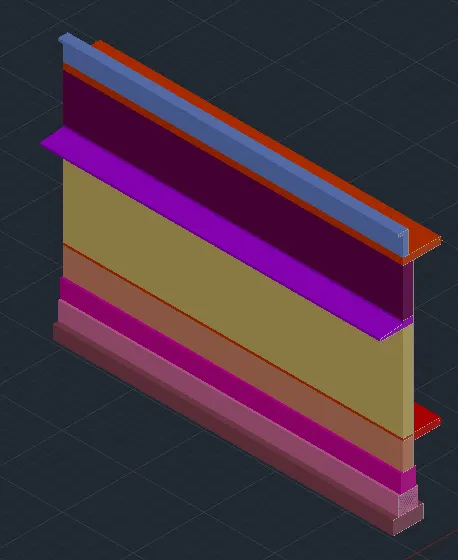
. Drawing 3D view of setion
. For Creating the 3D view initially boundaries are created
. Each boundary is created with its respective layer as current layer as shown in the following fig
. Extruding
. The create boudaries are to be extruded to a distance eof 7500 mm
. Select the boudaries by changing their respective current layer
. Door openning is added by drawing a rectangle at the door loacate from the plan view
. Then from the extruded part the door region is subtracted from the wall using subtract command
. After door shade remaining layer is extrude a shown in fig
. Rendering
. Rendering is done by adding the 3D view
. Use cam command to Create screenshot of the drawn point
. The material added for the component from the material browser are shown in fig
. Box mapping is done to adjust the texture of the wall
. Use cam command to create 2nd screenshot of the plot
RESULT :-
The 3D view of a wall spread footing and created a rendered view of the model with material successfuly in the autocad
in details .