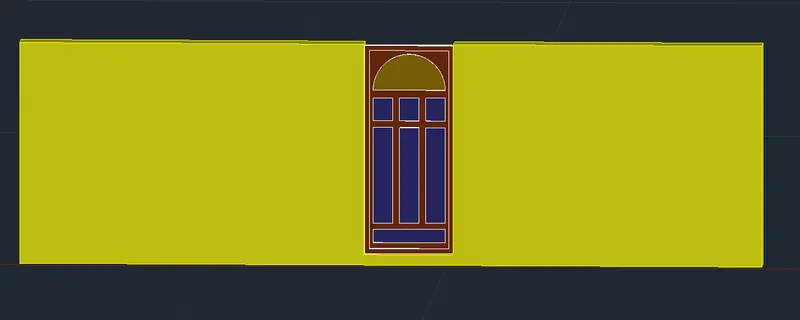
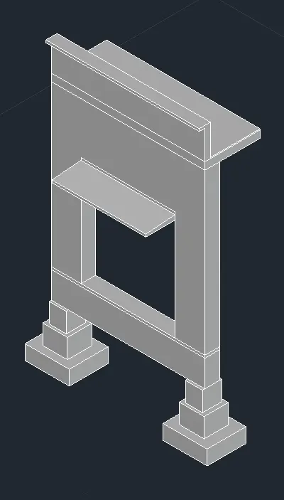
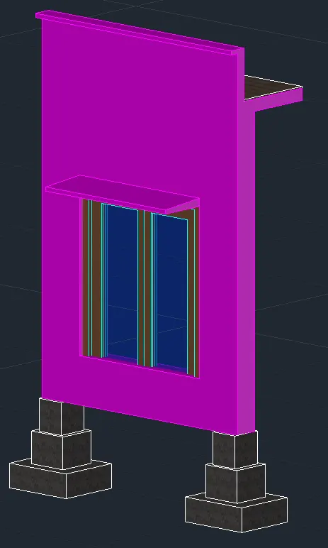
Creating 3D Isometric view of various structural elements in AutoCAD
To create a 3D isometric view of a building based on the given plan and elevation using AutoCAD software, you can follow the procedure outlined below:
-
Open AutoCAD and start a new drawing.
-
Set the appropriate units for the project. You can do this by typing "UNITS" in the command line, selecting the desired unit type (e.g., inches, millimeters, etc.), and specifying the desired precision.
-
Import or create the plan and elevation drawings of the building within the drawing space.
-
Switch to the 3D modeling workspace. You can do this by clicking on the "3D Modeling" workspace icon at the top of the AutoCAD window or by typing "3D" in the command line.
-
Begin by creating the base outline of the building in the plan view. Use AutoCAD's drawing tools such as lines, rectangles, circles, arcs, etc., to construct the basic shape of the building based on the provided plan.
-
Extrude the 2D outline to give height to the building. Use the "EXTRUDE" command and select the base outline of the building. Specify the desired height to extrude the shape and convert it into a 3D object.
-
Switch to the elevation view. You can do this by selecting the "Elevation" view from the "Views" panel in the "3D Modeling" tab.
-
Draw the vertical elements of the building such as walls, windows, doors, and other architectural features in the elevation view. Use appropriate tools and techniques to accurately represent the details provided in the elevation drawing.
-
Switch back to the plan view and adjust the height of the elements based on the elevation drawing. Make sure the vertical elements align properly with the extruded shape of the building.
-
Switch to an isometric view. You can do this by selecting the "Isometric" view from the "Views" panel in the "3D Modeling" tab.
-
Rotate and adjust the view to the desired angle to obtain an isometric perspective. Use the "3DORBIT" command to manipulate the view and get the best representation of the building.
-
Apply materials and textures to the 3D objects to enhance their appearance. Use the "MATERIALS" command to access the material library and apply materials to different surfaces of the building.
-
Adjust the lighting to simulate natural or artificial light sources. Use the "LIGHT" command to insert light sources and set their properties such as intensity and color.
-
Set up the camera view for the isometric view. Position the camera to get the desired perspective of the building. Use the "UCS" command to define the camera view and the "VIEW" command to adjust the view settings.
-
Once the isometric view is finalized, you can further refine the model by adding additional details, textures, and materials as necessary.
-
Save the 3D model in the desired file format.
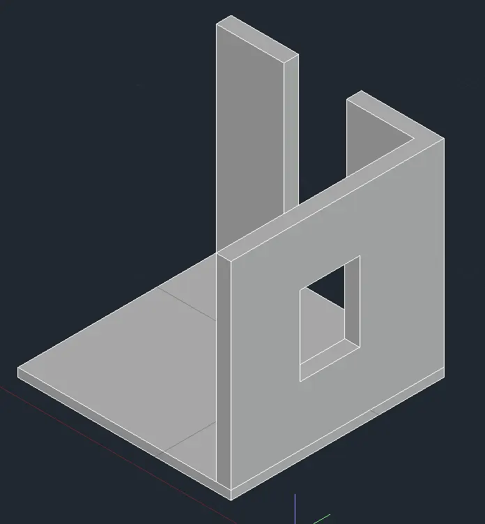
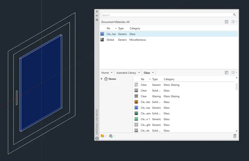
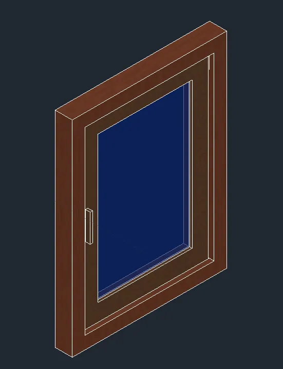
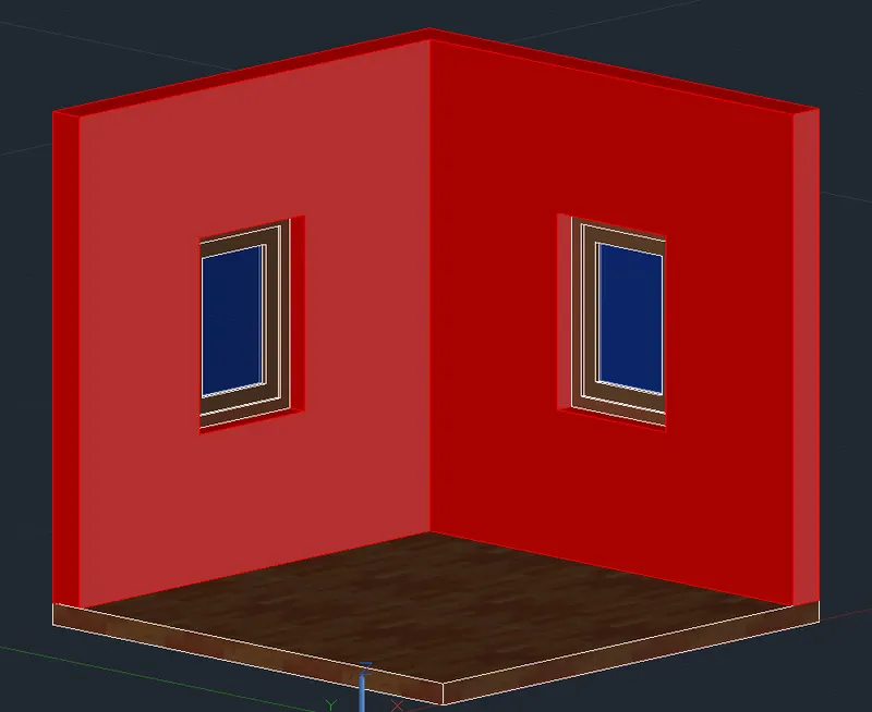
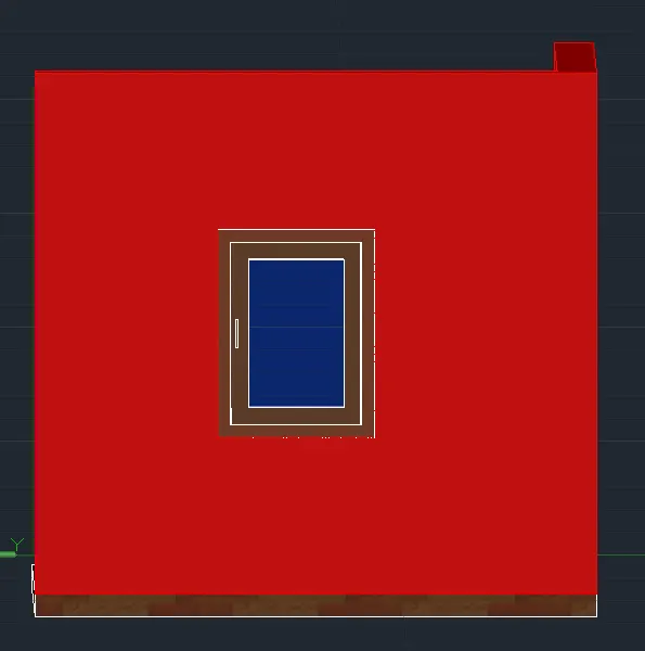
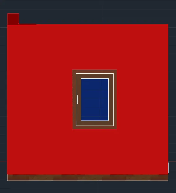
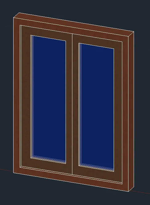
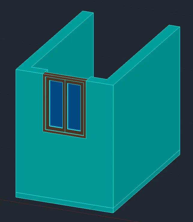
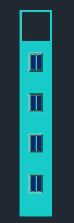
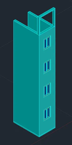
To create a 3D view of the building façade based on the given plan and elevation, and to examine the window detail using AutoCAD software, you can follow the procedure outlined below:
-
Open AutoCAD and start a new drawing.
-
Set the appropriate units for the project. You can do this by typing "UNITS" in the command line, selecting the desired unit type (e.g., inches, millimeters, etc.), and specifying the desired precision.
-
Import or create the plan and elevation drawings of the building within the drawing space.
-
Switch to the 3D modeling workspace. You can do this by clicking on the "3D Modeling" workspace icon at the top of the AutoCAD window or by typing "3D" in the command line.
-
Begin by creating the base outline of the building in the plan view. Use AutoCAD's drawing tools such as lines, rectangles, circles, arcs, etc., to construct the basic shape of the building based on the provided plan.
-
Extrude the 2D outline to give height to the building. Use the "EXTRUDE" command and select the base outline of the building. Specify the desired height to extrude the shape and convert it into a 3D object.
-
Switch to the elevation view. You can do this by selecting the "Elevation" view from the "Views" panel in the "3D Modeling" tab.
-
Draw the vertical elements of the building, including walls, windows, doors, and architectural features in the elevation view. Use appropriate tools and techniques to accurately represent the details provided in the elevation drawing.
-
For the window detail, zoom in to the area where the window is located in the elevation view. Use the "ZOOM" command to focus on the specific area.
-
Utilize AutoCAD's drawing tools to create the window detail accurately. Use lines, rectangles, arcs, and other tools to represent the dimensions, frame, and other components of the window.
-
Add additional details to the window, such as mullions, glass panels, handles, or any other elements specified in the plan and elevation. Ensure that the window detail accurately matches the provided information.
-
Switch back to the 3D view. You can do this by selecting the "3D View" from the "Views" panel in the "3D Modeling" tab.
-
Apply materials and textures to the 3D objects to enhance their appearance. Use the "MATERIALS" command to access the material library and apply materials to different surfaces of the building and the window detail.
-
Adjust the lighting to simulate natural or artificial light sources. Use the "LIGHT" command to insert light sources and set their properties such as intensity and color.
-
Set up the camera view for the 3D view. Position the camera to get the desired perspective of the building façade and the window detail. Use the "UCS" command to define the camera view and the "VIEW" command to adjust the view settings.
-
Once the 3D view and window detail are finalized, you can further refine the model by adding additional details, textures, and materials as necessary.
-
Save the 3D model in the desired file format.
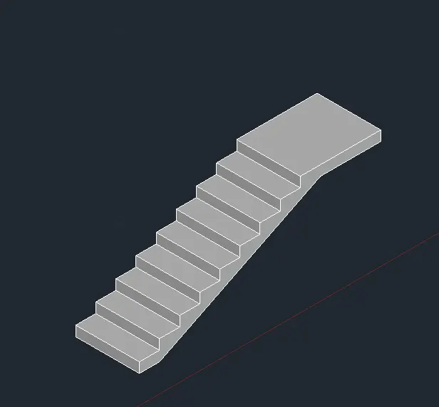
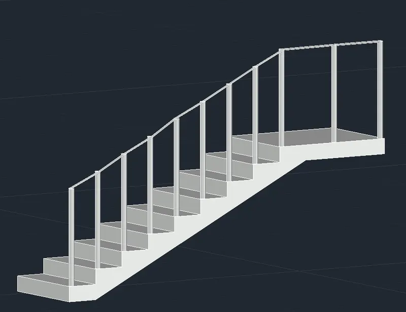
To create an isometric 3D view of a stair with railing based on the given plan and elevation, and assuming the size of the balustrades and handrails, you can follow the procedure outlined below using AutoCAD software:
-
Open AutoCAD and start a new drawing.
-
Set the appropriate units for the project. You can do this by typing "UNITS" in the command line, selecting the desired unit type (e.g., inches, millimeters, etc.), and specifying the desired precision.
-
Import or create the plan and elevation drawings of the stair within the drawing space.
-
Switch to the 3D modeling workspace. You can do this by clicking on the "3D Modeling" workspace icon at the top of the AutoCAD window or by typing "3D" in the command line.
-
Begin by creating the base outline of the stair in the plan view. Use AutoCAD's drawing tools such as lines, rectangles, circles, arcs, etc., to construct the shape of the stair based on the provided plan.
-
Extrude the 2D outline to give height to the stair. Use the "EXTRUDE" command and select the base outline of the stair. Specify the desired height to extrude the shape and convert it into a 3D object.
-
Switch to the elevation view. You can do this by selecting the "Elevation" view from the "Views" panel in the "3D Modeling" tab.
-
Draw the vertical elements of the stair, including the balustrades and handrails, in the elevation view. Use appropriate tools and techniques to accurately represent the dimensions and style of the balustrades and handrails based on the provided elevation.
-
For the balustrades, use AutoCAD's drawing tools to create the shape of the balusters or posts. Adjust their dimensions based on the specified size.
-
Create the handrails using lines, splines, or other tools. Ensure that the handrails are positioned correctly and are at the specified size and height.
-
Switch back to the 3D view. You can do this by selecting the "3D View" from the "Views" panel in the "3D Modeling" tab.
-
Apply materials and textures to the 3D objects to enhance their appearance. Use the "MATERIALS" command to access the material library and apply materials to different surfaces of the stair, balustrades, and handrails.
-
Adjust the lighting to simulate natural or artificial light sources. Use the "LIGHT" command to insert light sources and set their properties such as intensity and color.
-
Set up the camera view for the isometric 3D view. Position the camera to get the desired perspective of the stair, balustrades, and handrails. Use the "UCS" command to define the camera view and the "VIEW" command to adjust the view settings.
-
Once the isometric 3D view of the stair with railing is finalized, you can further refine the model by adding additional details, textures, and materials as necessary.
-
Save the 3D model in the desired file format.
To create a 3D view of a wall with a spread footing, focusing on the door opening and assuming the size of the parapet and coping, and to generate a rendered view with materials of your choice using AutoCAD software, you can follow the procedure outlined below:
-
Open AutoCAD and start a new drawing.
-
Set the appropriate units for the project. Type "UNITS" in the command line, select the desired unit type (e.g., inches, millimeters, etc.), and specify the desired precision.
-
Import or create the plans and elevation drawings of the wall within the drawing space.
-
Switch to the 3D modeling workspace. Click on the "3D Modeling" workspace icon at the top of the AutoCAD window or type "3D" in the command line.
-
Begin by creating the base outline of the wall in the plan view. Use AutoCAD's drawing tools, such as lines and rectangles, to construct the shape of the wall based on the provided plans.
-
Extrude the 2D outline to give height to the wall. Use the "EXTRUDE" command, select the base outline of the wall, and specify the desired height to extrude the shape and convert it into a 3D object.
-
Switch to the elevation view. Select the "Elevation" view from the "Views" panel in the "3D Modeling" tab.
-
Draw the vertical elements of the wall, including the door opening, in the elevation view. Use appropriate tools and techniques to accurately represent the dimensions and style of the door opening based on the provided elevation.
-
Create the door opening by drawing lines and rectangles at the desired location and size. Ensure that the door opening is positioned correctly and aligned with the wall.
-
Switch back to the 3D view. Select the "3D View" from the "Views" panel in the "3D Modeling" tab.
-
Add the spread footing to the bottom of the wall. Draw rectangles or other appropriate shapes to represent the spread footing based on the provided details and dimensions.
-
Create the parapet and coping by drawing additional elements on top of the wall. Use lines and rectangles to represent the parapet and coping at the specified size.
-
Apply materials and textures to the 3D objects to enhance their appearance. Use the "MATERIALS" command to access the material library and apply materials to different surfaces of the wall, door opening, spread footing, parapet, and coping.
-
Adjust the lighting to simulate natural or artificial light sources. Use the "LIGHT" command to insert light sources and set their properties such as intensity and color.
-
Set up the camera view for the 3D view. Position the camera to get the desired perspective of the wall, door opening, spread footing, parapet, and coping. Use the "UCS" command to define the camera view and the "VIEW" command to adjust the view settings.
-
Once the 3D view is finalized, proceed to create a rendered view of the model using AutoCAD's rendering capabilities.
-
Access the rendering settings using the "RENDER" command. Adjust various parameters, including quality, lighting, and materials, to attain a realistic render.
-
Execute the rendering process to generate a photorealistic image of the 3D model with the specified materials.
-
Save the rendered image in the desired format.