Creating 3D Isometric view of various structural elements in AutoCAD
Q-1. Create a 3D Isometric View of the building with plan and elevation given.
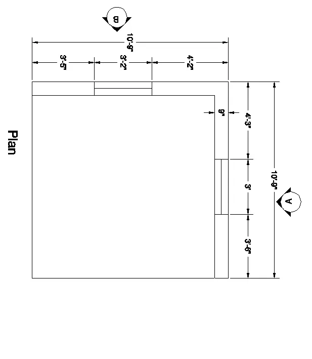
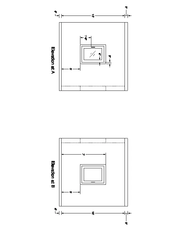
AIM AND INTRODUCTION : 3D Isometric View of the building with given plan and elevation given is to be created.
PROCEDURE IN DETAIL :
Plan of the building is created using the following command-
- RECTANGLE command
- Line command
- DIM (A/C) command
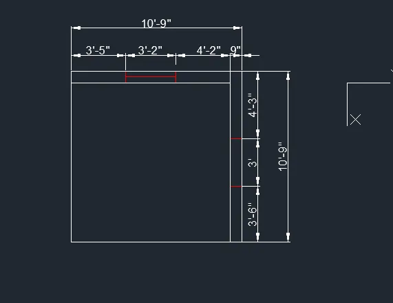
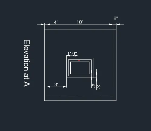
Elevation at A is created using following commands-
- XL (H/V) commands for reference lines from the plan in horizontal and vertical directions
- TRIM & DELETE commands for removing undesired lines
- OFFSET command is used for creating frame and panel of window
- DIM (A/C) command for dimensioning
- MTEXT(MT) command is used to create text
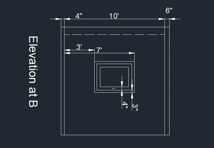
Elevation at B is created using following commands-
- XL (H/V) commands for reference lines from the plan in horizontal and vertical directions
- TRIM & DELETE commands for removing undesired lines
- OFFSET command is used for creating frame and panel of window
- DIM (A/C) command for dimensioning
- MTEXT(MT) command is used to create text
- Plan is converted to isometric view
- REGION command is used to create region on the wall portionlevations
- EXTRUDE command is used to create height of the wall as given in E
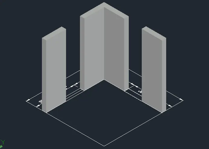
Windows are also extruded to the height of 10'-10" as given in elevation using REGION and EXTRUDE command
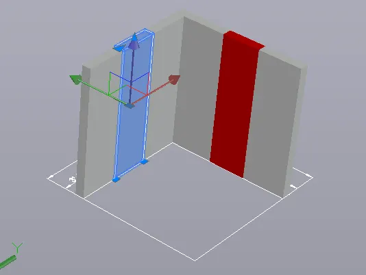
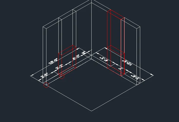
In top view 2D wire frame creating rectangle in window portion using RECTANGLE command and creating regions using REGION command a shown in the snap below-
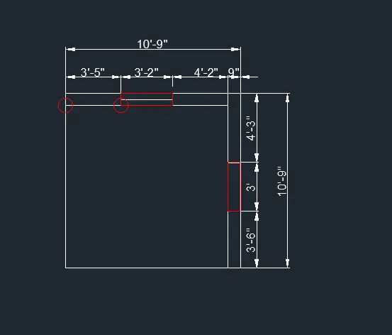
In Custom view 2D wire frame window regions are extruded to the height of 4' as shown below using EXTRUDE command
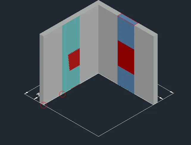
Changing the view to Custom and shaded and assigning the windows different colors using SOLIDEDIT command for better identification of windows as shown below-
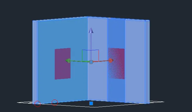
UNION command is used to combined the windows and other part as one solid as shown below-
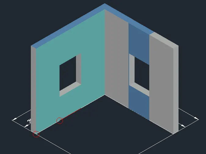
SUBTRACT command is used to remove the solid windows from the entire solid to create opening for fixing frame and shutters of windows as shown-
Window frame and shutter is created using RECTANGLE and OFFSET command -
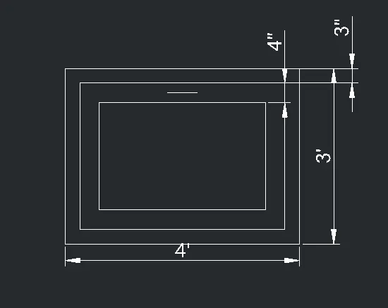
EXTRUDE command is used to assign thickness to the Window frame ( 5" assumed), Style ( 3" assumed) and shutter/panel (1" assumed) and seperating different components using MOVE command as shown-
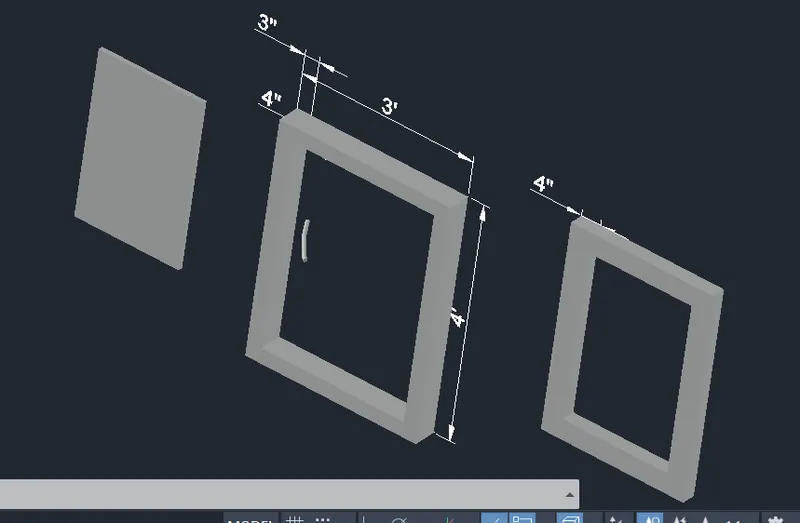
Panel is fixed centrally to the Style using MOVE command and colours are assigned using SOLIDEDIT command as shown-
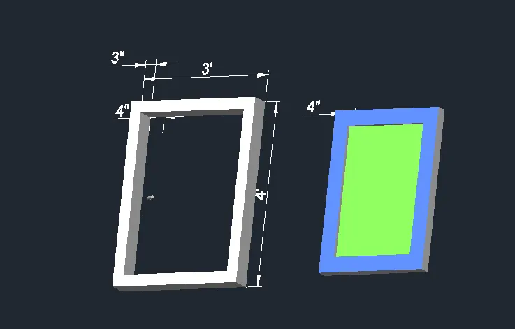
Style along with panel is fixed in window frame using MOVE and SOLIDEDIT commands-
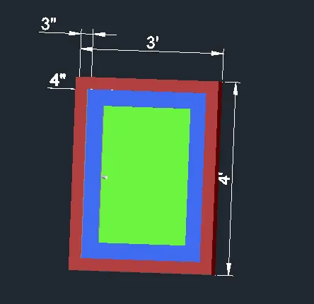
Window is fixed centrally in the opening created in the wall using MOVE command
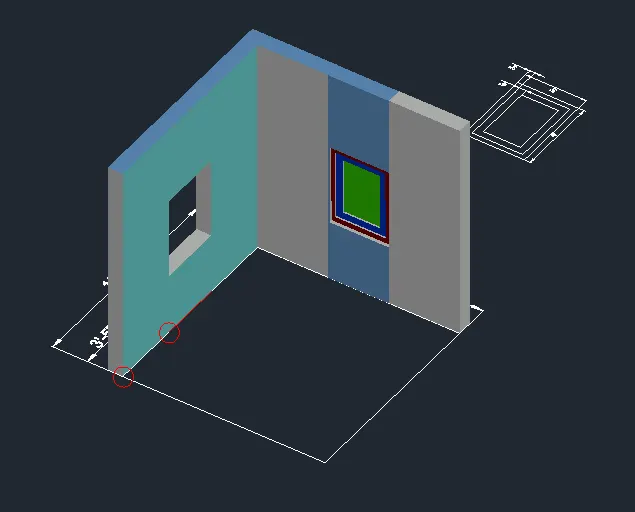
Another window is created and fixed at opening in the wall as per procedure followed in earlier step as below-
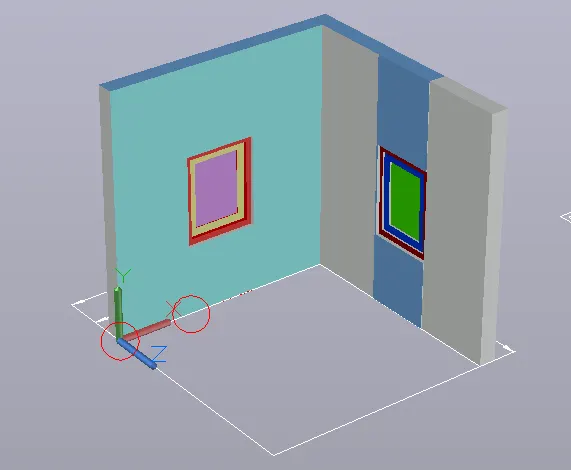
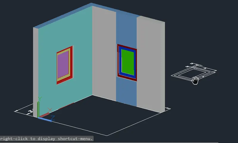
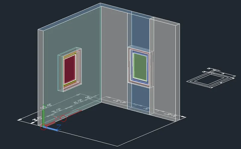
Hidden view-
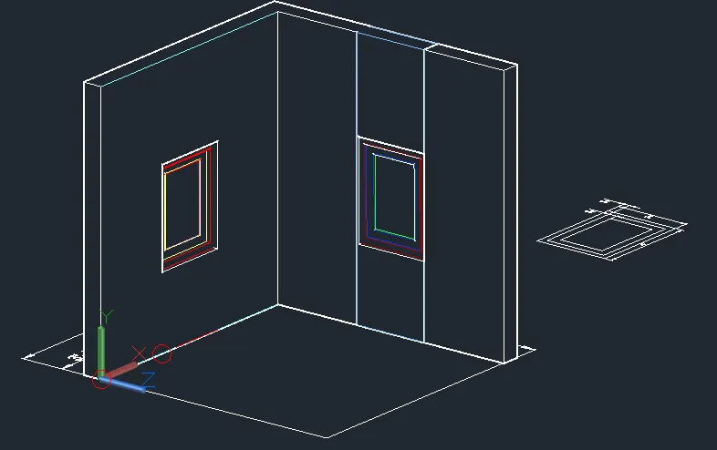
X-Ray view-
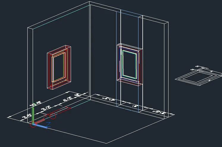
Wire Framed view-
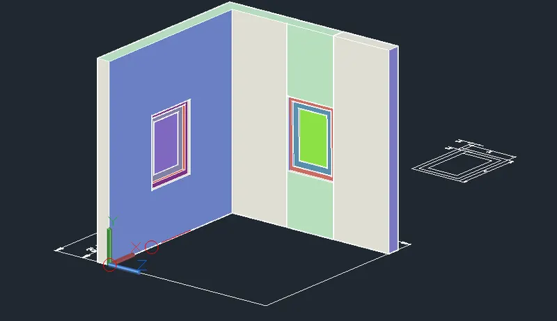
Conceptual view-
RESULT : Thus as desired 3D Isometric View of the building with given plan and elevation is created. Various steps have been narrated with snaps and .DWG file is attached for reference with file name " ACCHQ1.
------------------------------------xxxxxxxxxxxxxx---------- END OF Q-1 ---------------xxxxxxxxxxxxxxxxxxxxxxx--------------
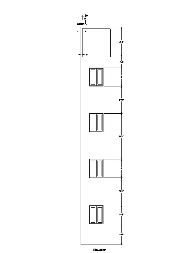
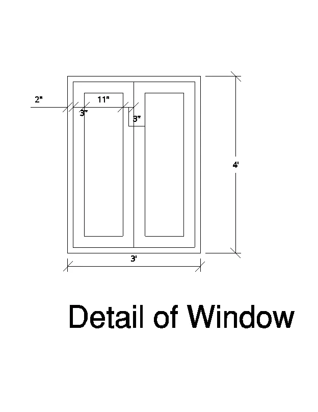
Q-2. Create the 3D View of the Building Façade as given in the plan and elevation. Also, see the detail of the window.
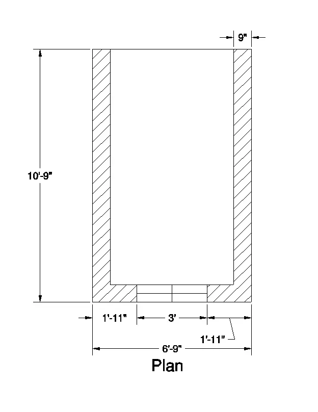
AIM AND INTRODUCTION-
3D View of the Building Façade as given in the plan and elevation and detail of the window is required to be created .
PROCEDURE IN DETAIL :
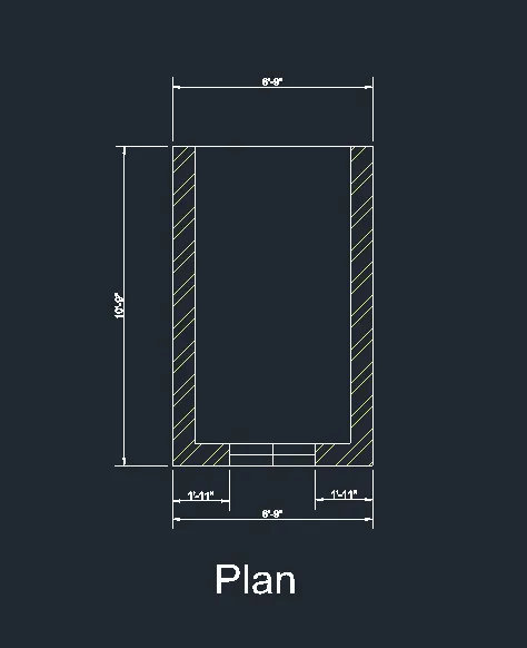
Plan of Building Facade is created usinf following commands-
- RECTANGLE command to create rectanlgle then exploding it using EXPLODE command.
- OFFSET command to create thickness of wall.
- TRIM command to delete unwanted line segments.
- HATCH command to assign hatching to brick wall section.
- DIMENSIONALIGNED (DIMA) for dimensioning.
- LINE command to draw line segment.
- MT command to write text'
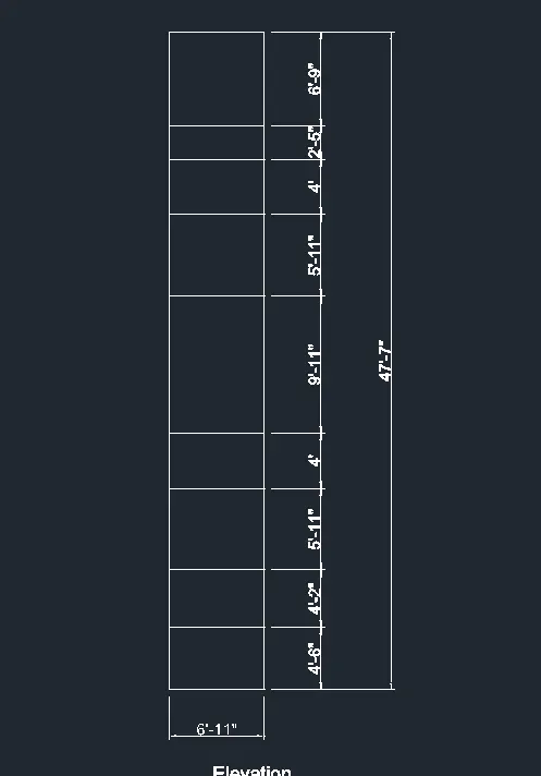
Elevation is created using following commands-
- RECTANGLE command to create rectanlgle then exploding it using EXPLODE command.
- OFFSET command to create thickness of wall.
- TRIM command to delete unwanted line segments.
- DIMENSIONALIGNED (DIMA) AND DIMENSIONCONTINUE (DIMC) for dimensioning.
- LINE command to draw line segment.
- MT command to write text'
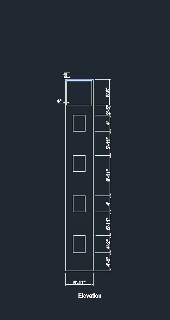
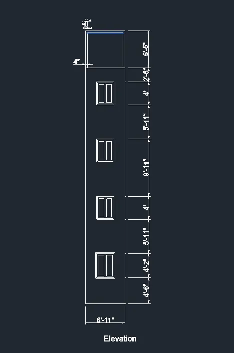
Walls excluding window are extruded to the height of 40'-10" using following commands-
BOUNDARY command- for creating region/surface.
EXTRUDE command- for assigning height to the Building.
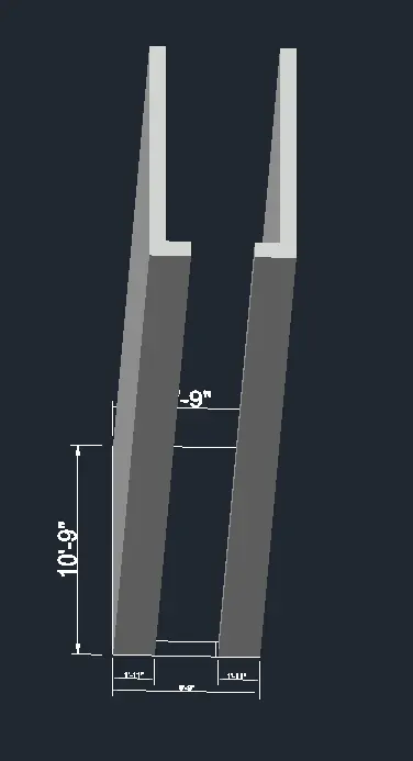
- Rectangle is created in the portion of window using RECT command.
- Region is created in the created rectangle using BOUNDARY command.
- Window is extruded to the building height of 40'-10" using EXTRUDE command.
- In the hidden view UNION command is used to create a single solid out of vwalls and window.
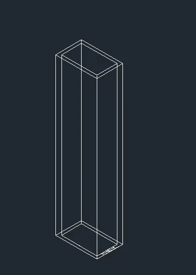
- 2D wireframed is created as shown below-
- Again rectangle is created in the window portion using RECT command.
- MOVE command is used to move the rectangle to the height of 4'-6" od Sill level as given.
- EXTRUDE command is used to create window height of 4'-2" as given.
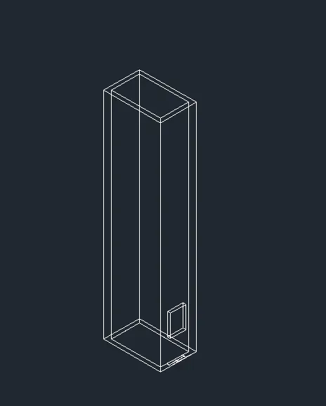
SUBTRACT command is used to subtract extruded window from entire building then HIDDEN option is used to create view as given-
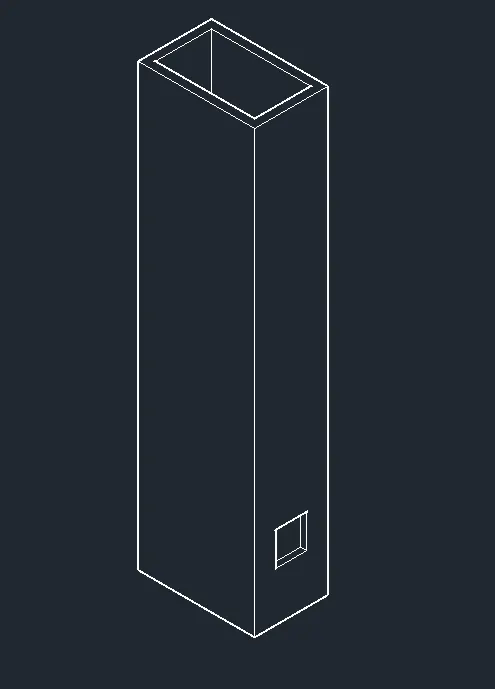
SHADED option to view window opening-
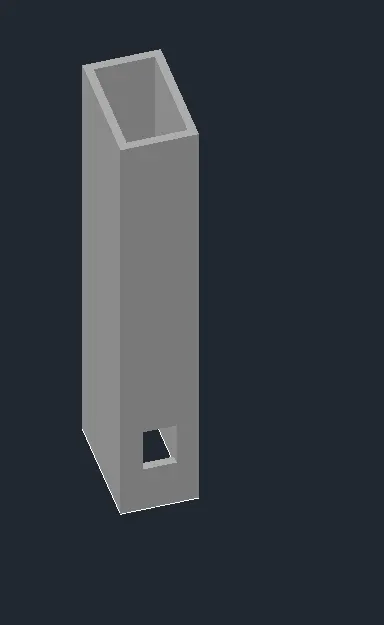
For second window opening-
- Rectangle is created in the portion of window using RECT command.
- MOVE command is used to move the window to the height as given in elevation.
- Region is created in the rectangle using BOUNDARY command.
- Window is extruded to the building height of 4' using EXTRUDE command.
- SUBTRACT command is used to subtract window from the building to create opening.
- Shaded view is created as shown below-
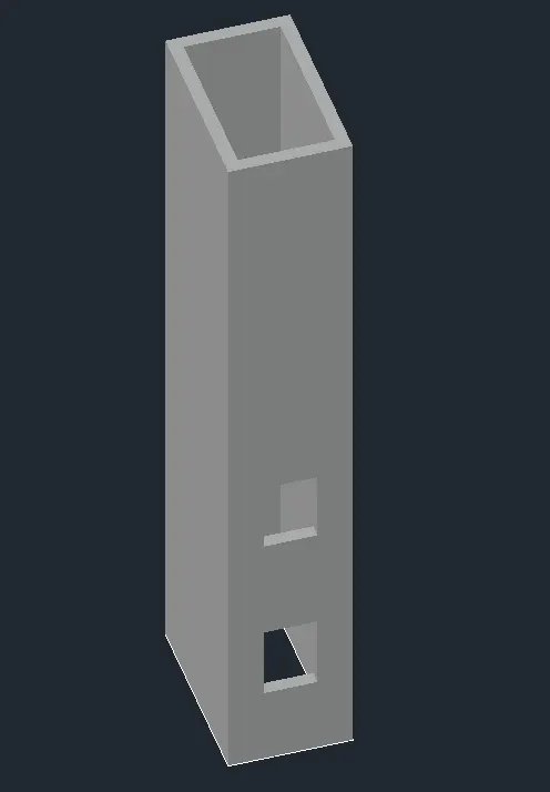
Roof top portal frame is created using following commands-
- POLYLINE (PL) command- to create portal frame
- RECTANGLE command- to creat section of portal frame (9"x4")
- SWEEP command- to assign sectional profile to the portal frame
- SOLIDEDIT command - to impart colour to the surface of portal frame
- MOVE command- to move the frame to the appropriate location of the building as shown below-
Window frame, Style and panels are created using following commands-
- RECTANGLE command
- EXPLODE command
- TRIM command
- LINE command
- OFFSET command
- REGION command
- EXTRUDE command
- SUBTRACT command
- DELETE command
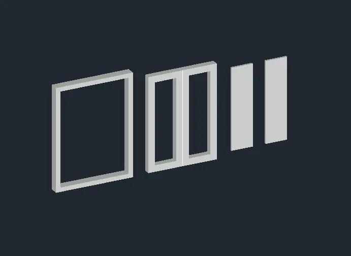
Roof top portal frame is created using following commands-
- POLYLINE (PL) command- to create portal frame
- RECTANGLE command- to creat section of portal frame (9"x4")
- SWEEP command- to assign sectional profile to the portal frame
- SOLIDEDIT command - to impart colour to the surface of portal frame
- MOVE command- to move the frame to the appropriate location of the building as shown below-
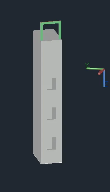
Window frame , Styles and shutters are fixed together and then fixed in the window opening usinf following commands-
- MOVE command
- SOLIDEDIt command
- UNION command
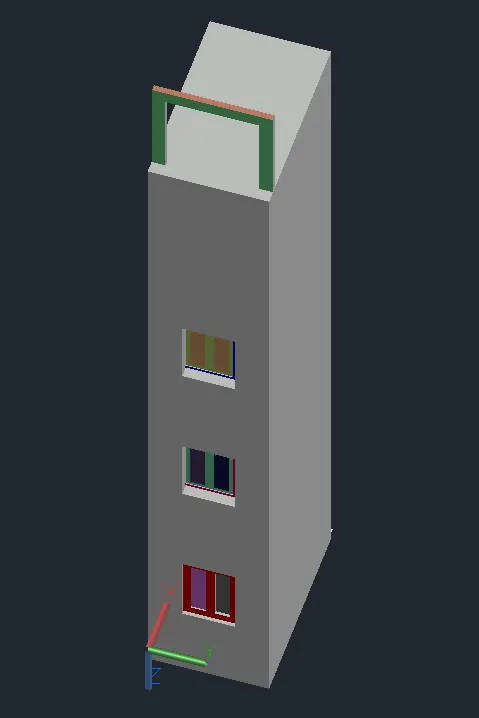
Conceptual view-
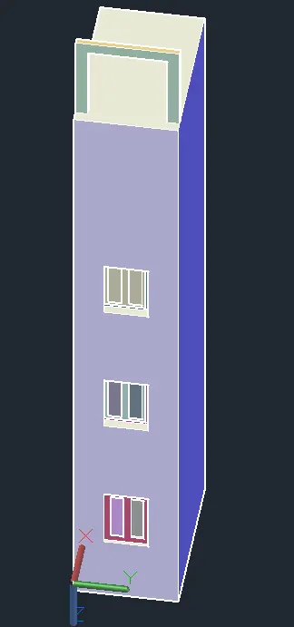
Shaded with edges view-
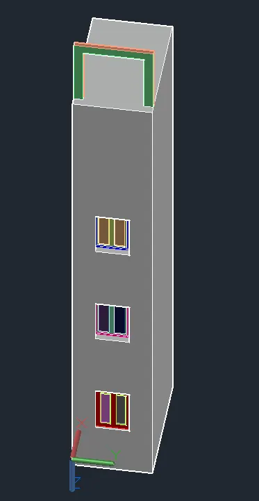
Shades of Gray view-
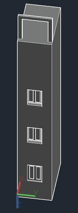
Hidden view-
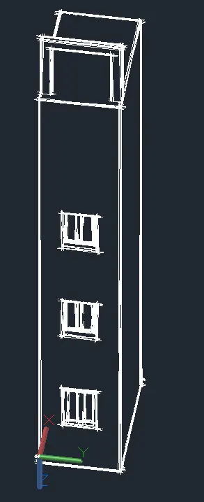
Sketchy view-
Realistic view-
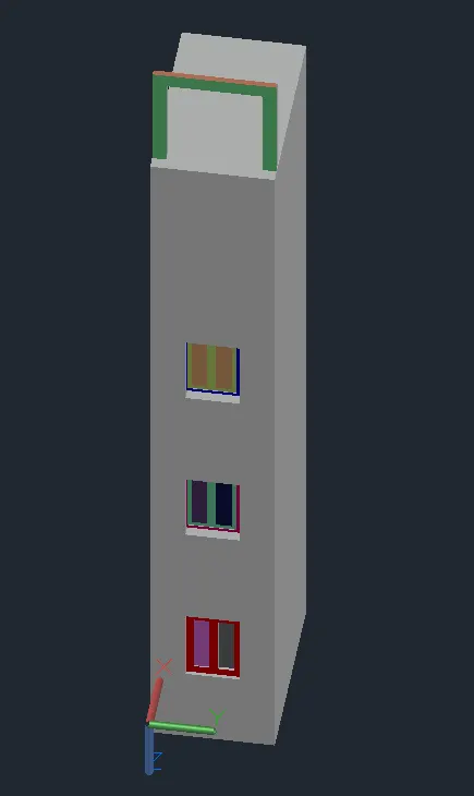
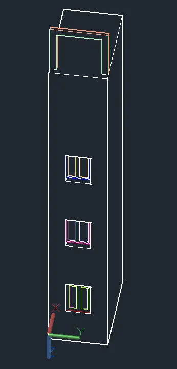
2D wire frame view-
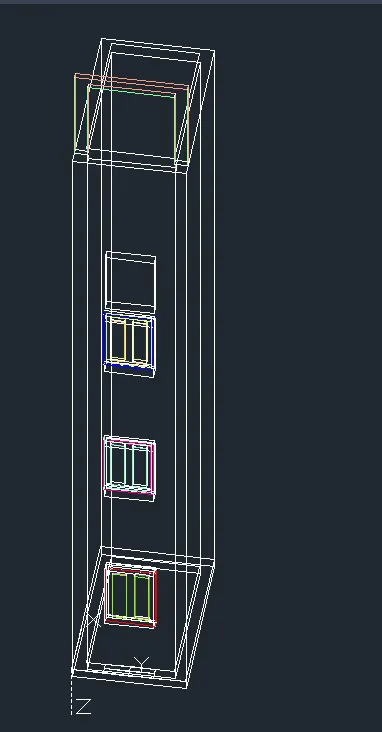
RESULT : 1) Thus 3D View of the Building Façade as given in the plan and elevation is created incorporating detail of the window.
2) Snap shots of each step are also pasted above
3) .DWG file is attached with file name ACCH13Q2.DWG.
--------------------------xxxxxxxxxxxxxx------------- END OD Q-2 -----------------xxxxxxxxxxxxxxxx---------------------
Q-3. Create the ismoteric 3d view of a stair with railing as shown in the plan and elevation. Assume the size of the balustrades and the hand rails.
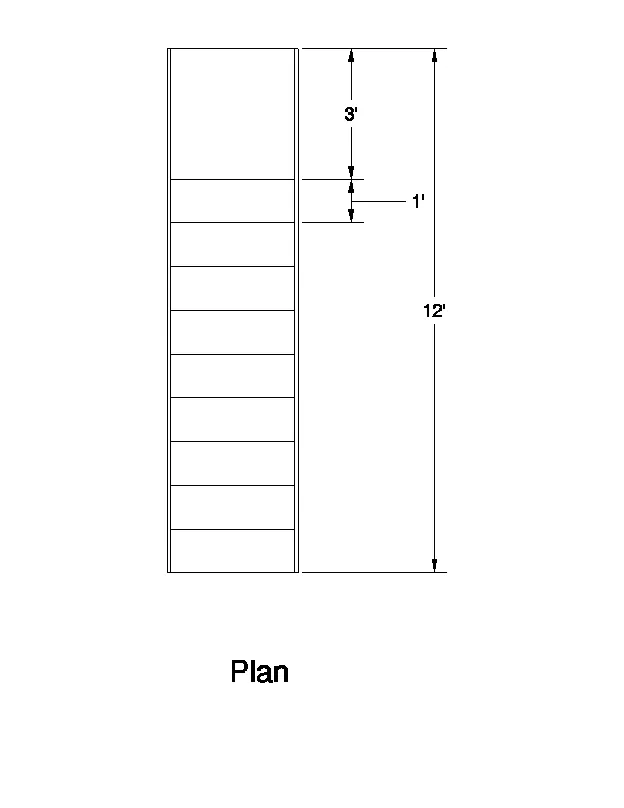
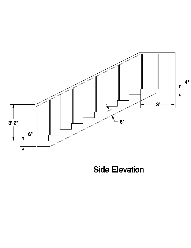
AIM AND INTRODUCTION : Ismoteric 3d view of a stair with railing as shown in the plan and elevation is to be created assuming the size of the balustrades and the hand rails.
PROCEDURE IN DETAIL :
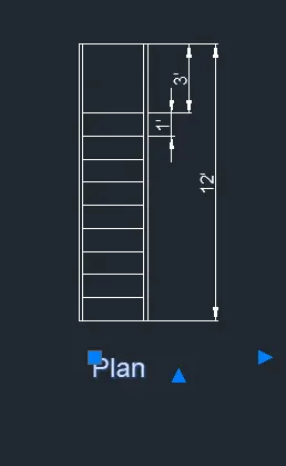
Plan of staircase is created using following commands-
- RECTANGLE command
- EXPLODE command- Rectangle is broken into its line segments.
- OFFSET command
- DIML command- for creating dimension
- MT command- for creating text
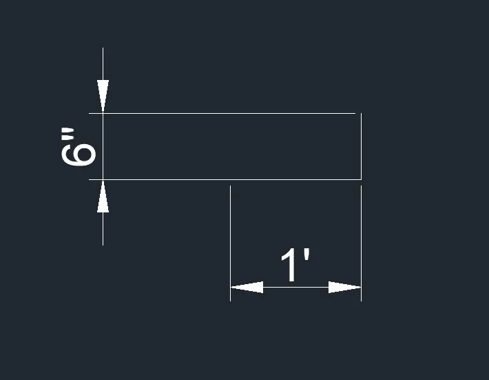
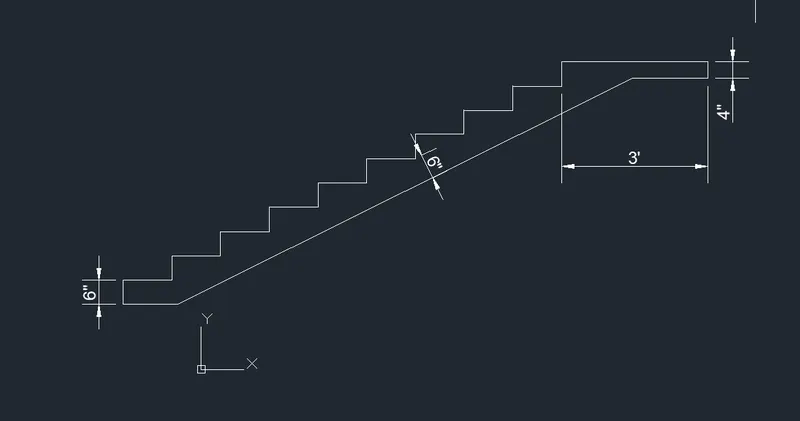
Tread of 12" and Rise of 6" is created using LINE command as shown below-
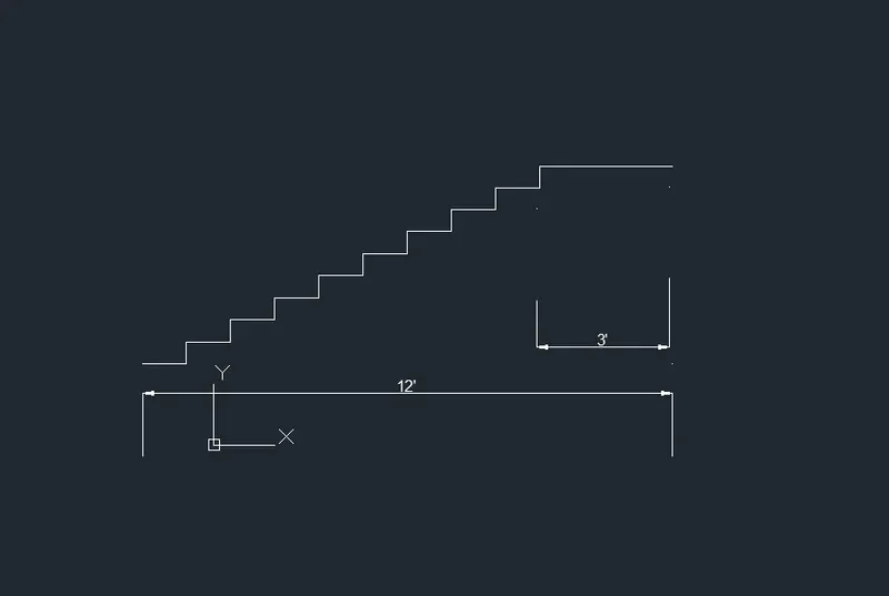
9 steps have been created as given using COPY & PASTE command as shown below-
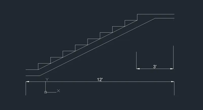
Waste slab of thickness 6" and Landing slabs of thickness 4" as given are created using following command-
- LINE (L) command
- OFFSET (O) command
- TRIM ( TR) command
- EXTEND (EX) command
Dimensioning is done using DIMA & DIML command and unwanted reference line joining each step is removed using DELETE command
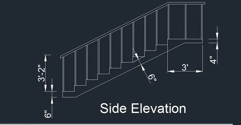
Hidden 3D view of stair case-
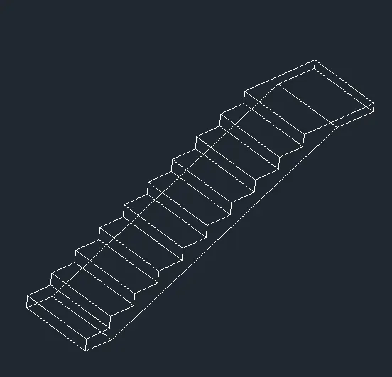
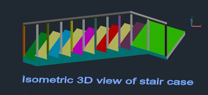
Shaded 3D view of stair case-
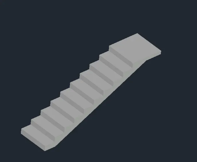
SOLIDEDIT command is used for assigning colour to various components-
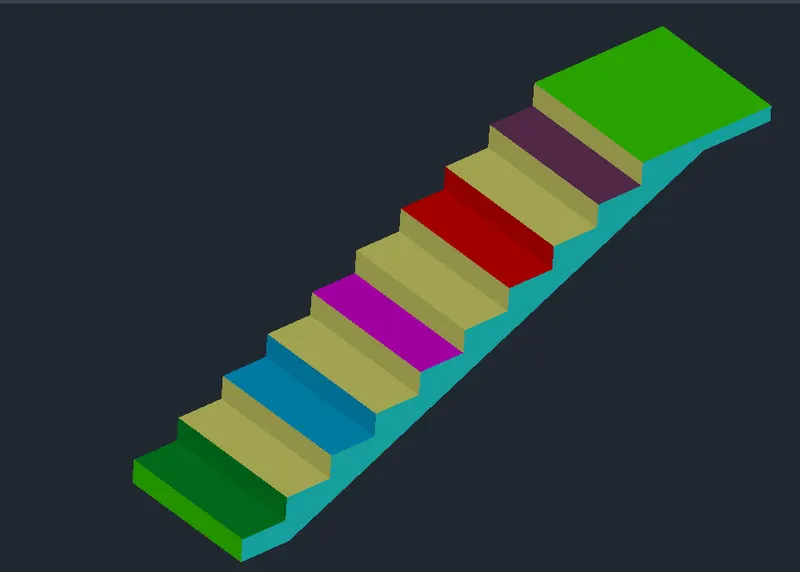
Hand rail ic created from circular section of diameter 4" using following commands-
- LINE command
- OFFSET command
- CIRCLE command
- EXTRUDE command
- SWEEP command
- COPY command ( CTRL+C)
- PASTE command ( CTRL+V)
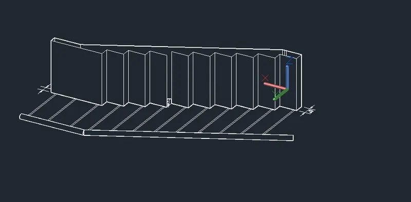
Another view of stair case created using 3DROTATE command-
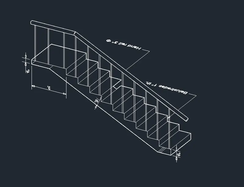
Isometric view of Stair case in which Text is created using MTEXT (MT) command
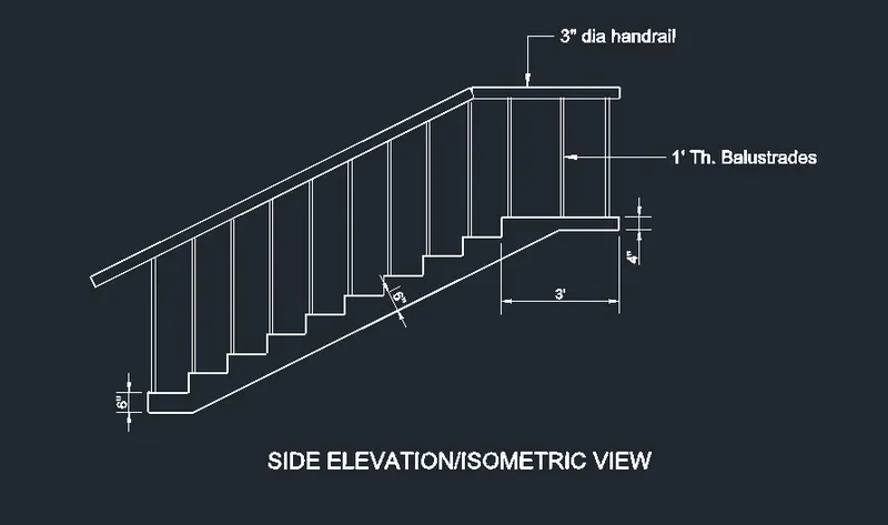
Railing/hand rail and balustrades are created using the following commands-
- LINE command
- CIRCLE command
- SWEEP command
- COPY command
- PASTE command
- MOVE command
- SOLIDEDIT command
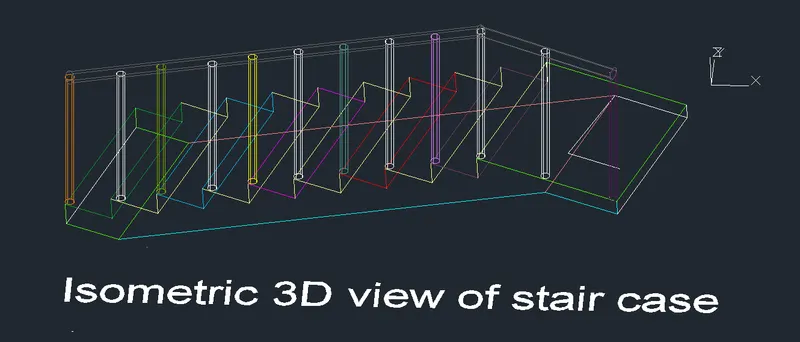
2D wire frame-
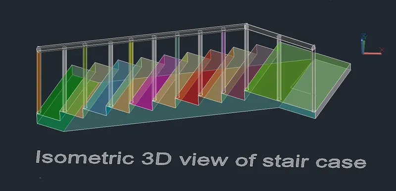
X-RAY view-
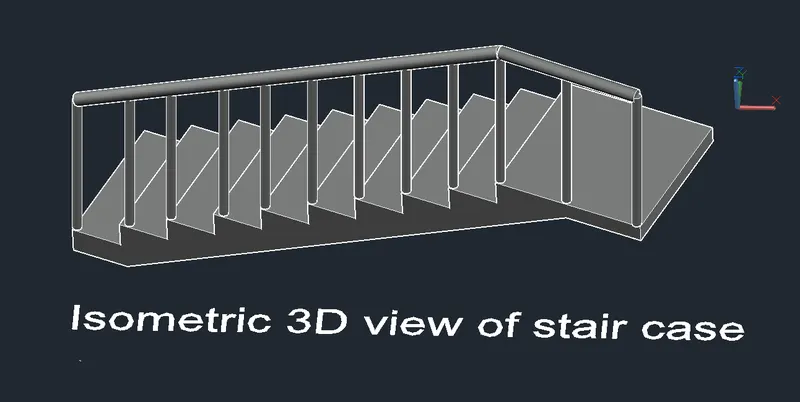
Shade of gray view-
Shaded with edges view-
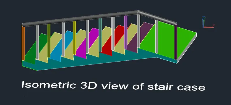
Hidden view-
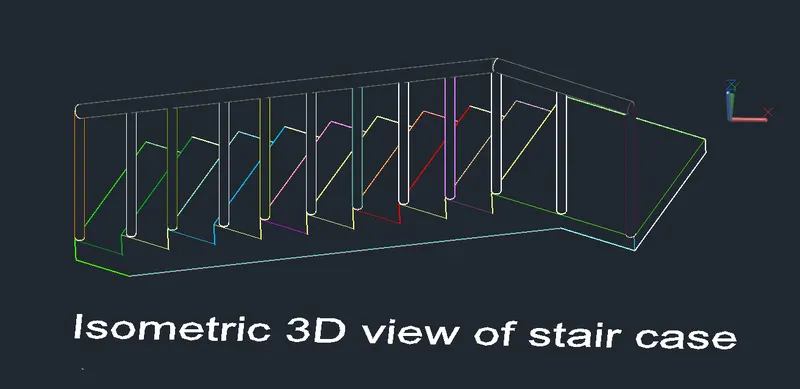
RESULT : Thus Ismoteric 3d view of a stair with railing as shown in the plan and elevation is created assuming the size of the balustrades as 1" & and the hand rails 3"
DWG file with name ACCH13Q3 R is attached
-----------------------XXXXXXXXXXXXXXXXXXXXXXXXX--------------- END OF Q-3----------------XXXXXXXXXXXXXXXX------------
4. Create the 3D view of a Wall with spread footing . Create the Door opening only. Assume the size of the parpaet and the coping. See the plans and elevation for the details. Also, create a rendered view of the model with materials as of your choice.
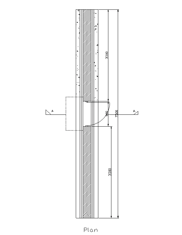
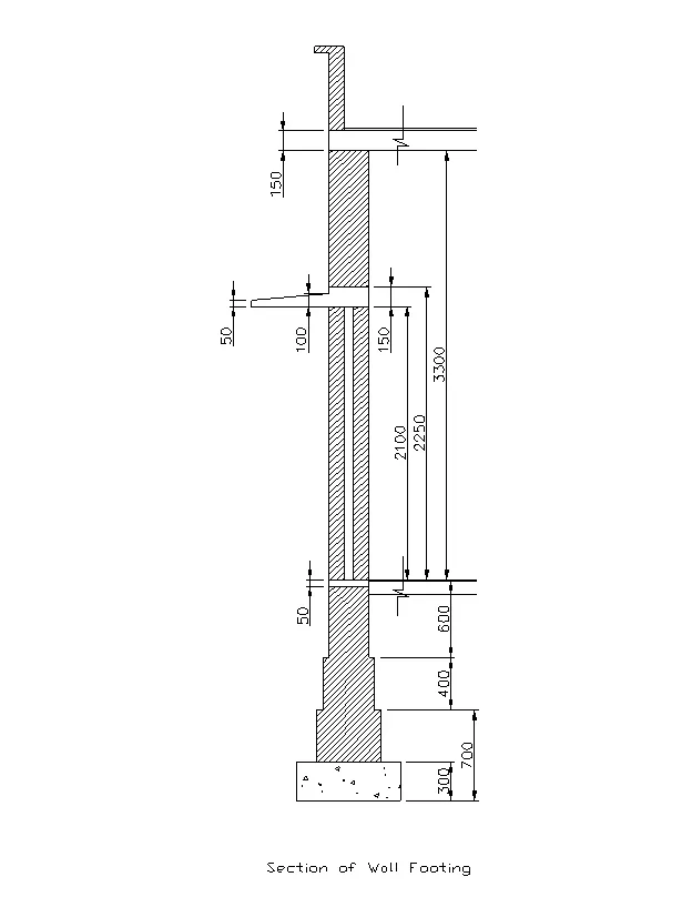
AIM AND INTRODUCTION : 3D view of a Wall with spread footing and Door opening only to be created using given plan and section. Rendered view of the model with materials is also to be created.
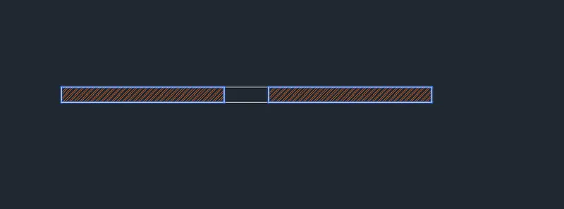
PROCEDURE IN DETAIL : Wall of thickness 300 mm ( assumed) is created using RECTANGLE command & LINE command as shown below -
HATCH command is used to assign hatching to wall and then assigning colour to it as shown below-
Assuming the offst of wall = 100 mm on both side
Assuming offset of wall footing = 200 mm
Using OFFSET command two projection on both the side of wall are created
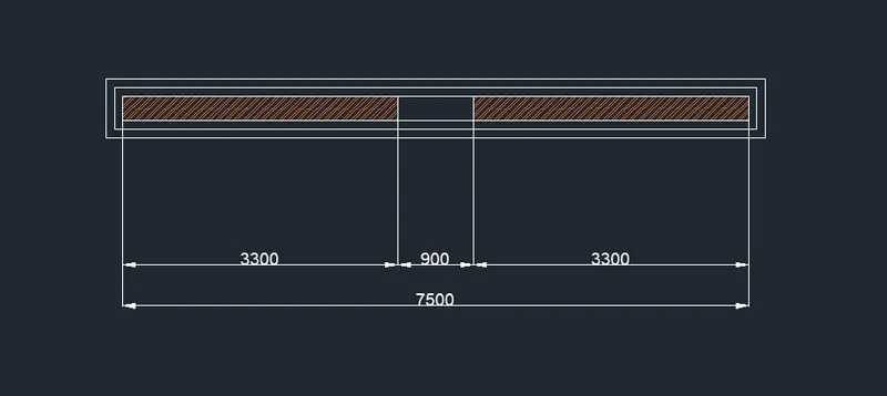
- Offset of footing of wall is created using OFFSET command then colours are assigned to different lines
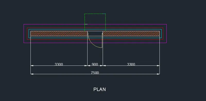
- Door and its fram is created using following commands-
- CIRECLE command
- LINE command
- RECTANGLE command
- TRIM command
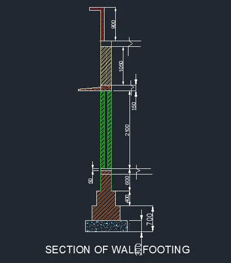
Section of rhe wall footing is created using following commands-
- LINE command- For drawing line segment
- OFFSET command- Providing offset distance
- TRIM command- For removing remaining part of unwanted line segment
- MULTITEXT(MT)- For writing text
- DELETE command- For deleting undesired lines
- HATCH command and its property- For hatching different cimponents
- DIMENSION ALIGNED ( DIMA) command- for dimensioning
From the plan of wall footing only footing is extruded to the height of 300 mm after deleting all other offset of wall as follows-
DELETE command- For deleting other part except footing.
REGION command is used to create the REGION.
EXTRUDE command is used to extrude the footing to depth of 300 mm as shown below-
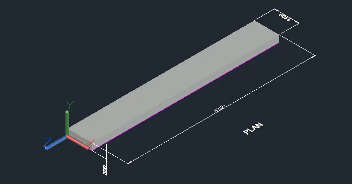
From the plan of wall footing only first projection of wall is extruded to the height of 400 mm after deleting all other offset of wall and footing as follows-
DELETE command- For deleting other part except footing.
REGION command is used to create the REGION.
EXTRUDE command is used to extrude the footing to depth of 400 mm as shown below-
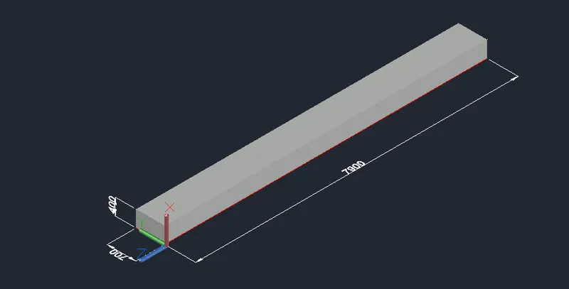
From the plan of wall footing only second projection of wall is extruded to the height of 400 mm after deleting all other offset of wall and footing as follows-
DELETE command- For deleting other part except footing.
REGION command is used to create the REGION.
EXTRUDE command is used to extrude the footing to depth of 400 mm as shown below-
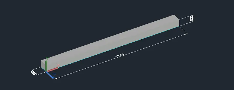
Wall of height 3300 and thickness 300 is created using the commands as used in the preceeding steps as shown below-
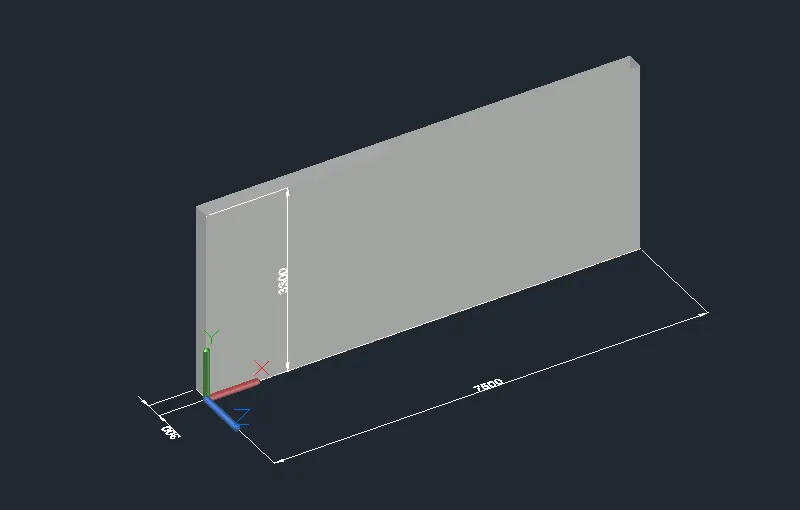
Door opening of 900 mm x 2100 mm is created extruding wall on both side of door opening to the feight of 3300 mm using EXTRUDE command.
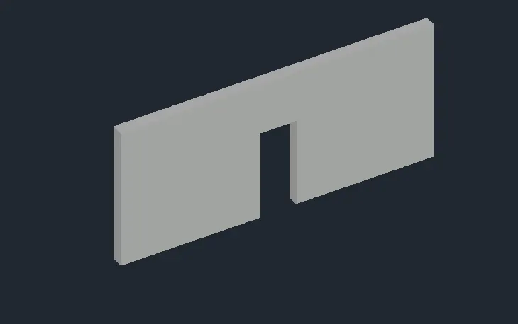
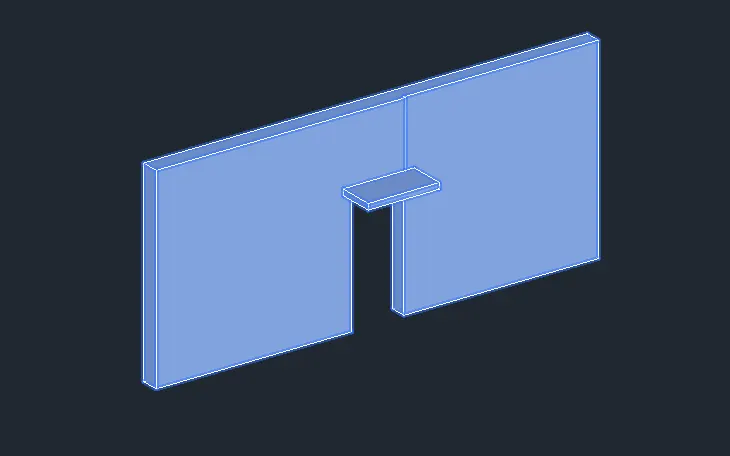
- Wall is created above door opening of 2100 mm creating rectangle of 900x 300 using RECTANGLE command.
- REGION command is used to create surface in rectangle.
- MOVE command is used to move the rectangular surface the height of 2100 just at the top of door opening.
- EXTRUDE command is used to the height of 1200 mm to creat solid wall over the door opening for creation of sunshade.
- RECTANGLE of size 1200 x100 mm on the front face of wall ( with UCS setting) touching the door top opening and projecting 150 mm on either side is created using RECTANGLE command.
- EXTRUDE command is used to extrude sunshade to 600 mm perpendicular to the wall face as shown below-
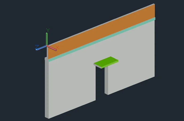
Beam of thickness 150 mm and parapet wall of height 900 mm is created in the following way-
RECTANGLE command is used to create beam of 7500 mm x 300 mm .
REGION command is used to create surface
EXTRUDE command is used to extrude to the depth of 150 mm .
SOLIDEDIT command is used to assign colour to the beam .
MOVE command is used to place the beam over the wall as shown below-
Beam of thickness 150 mm and parapet wall of height 900 mm is created in the following way-
RECTANGLE command is used to create beam of 7500 mm x 300 mm .
REGION command is used to create surface
EXTRUDE command is used to extrude to the depth of 150 mm .
SOLIDEDIT command is used to assign colour to the beam .
MOVE command is used to place the beam over the wall as shown below-
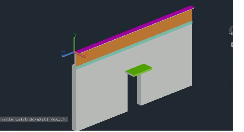
COPING over the parapet wall is created as per the above commands as shown below-
3D view of wall footing-
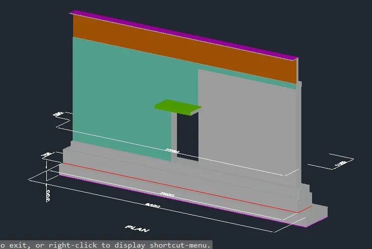
RESULT : Thus 3D view of a Wall with spread footing and Door opening only is created using given plan and section. Rendered view of the model with materials is also to be created. .DWG file is attached with file name- ACCH13Q4
------------------------------xxxxxxxxxxxxxxx------------- END OF Q4- --------------------xxxxxxxxxxxxx -------------------------