Creating 3D Isometric view of various structural elements in AutoCAD
AIM:-
- To create a 3D Isometric view of various structural elements in AutoCAD.
INTRODUCTION:-
- An isometric drawing is a 3d representation of a particular object.
- In an isometric drawing, the object appears to be viewed from above one corner with the axes being set out from this corner point.
COMMANDS USED:-
- Units
- Line
- rectangle
- UCS
- Polyline
- Dimlinear
- Region
- Extrude
- Subtract
- Box
- 3Dorbit
- Hide
- Explode
- Boundary
- Presspull
- Sweep
- Union
- 3D rotate
- Erase
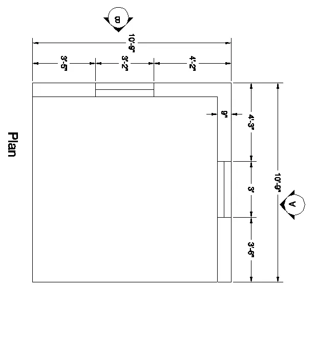
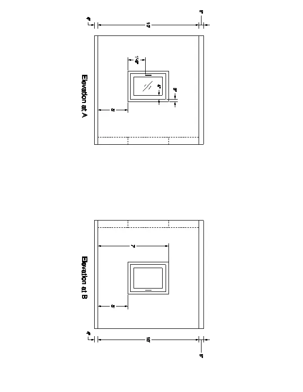
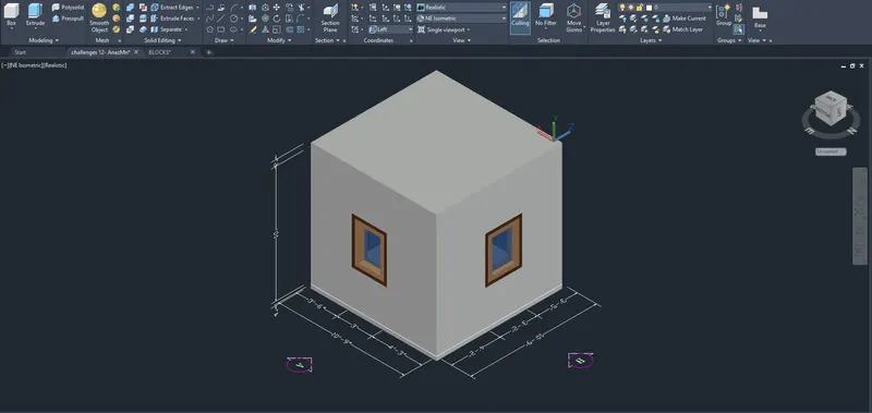
1. Create a 3D Isometric View of the building with the plan and elevation given.
AIM:-
- To Create a 3D Isometric View of the building with the plan and elevation given
PROCEDURE:-
- Open Autocad and set the units and limits
- Draw the rectangle using the rectangle command
- Draw the window of 3x9" and 9"x3'2"
- Draw the elevation of A and the elevation of B
- Draw the wall using the extrude command
- Use the layers for coloring

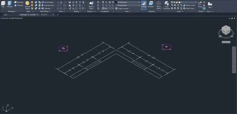
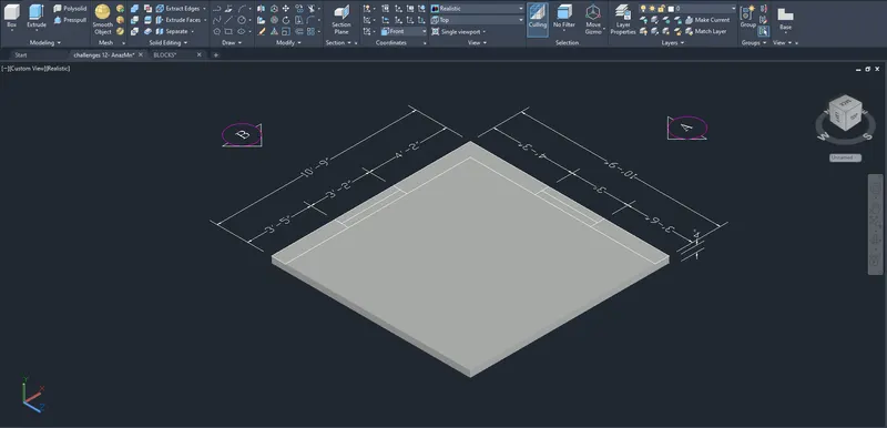
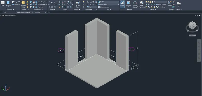
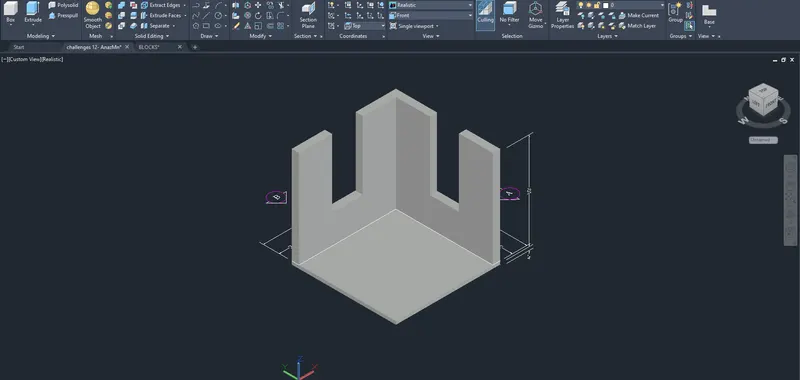
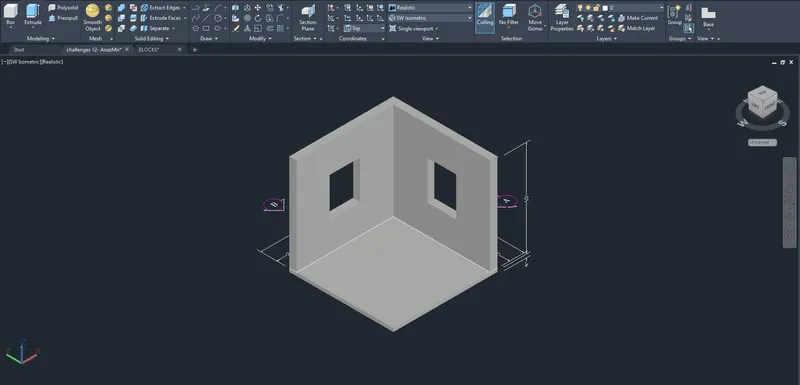
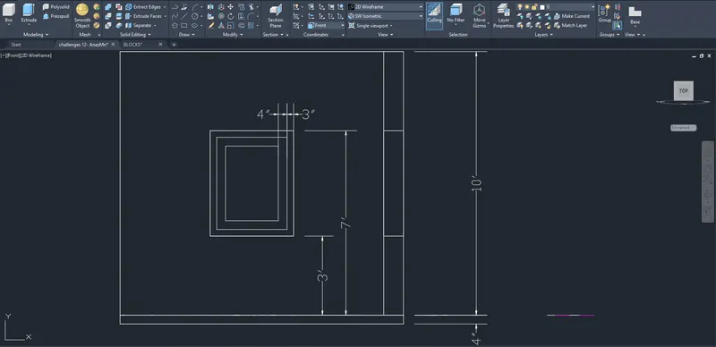
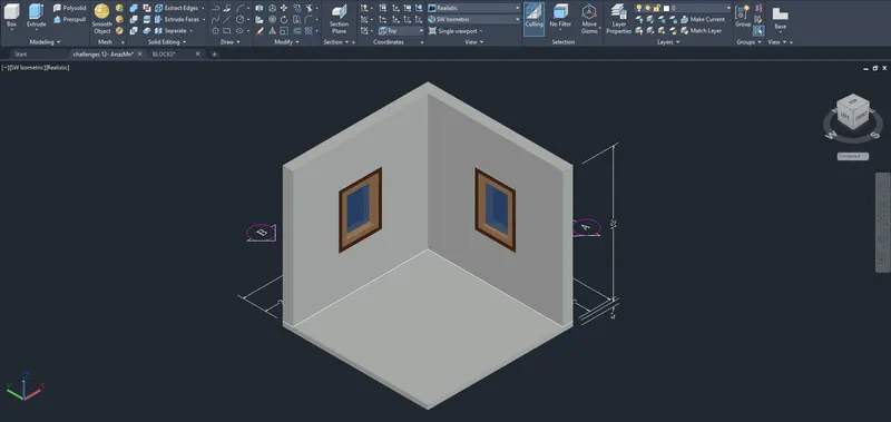
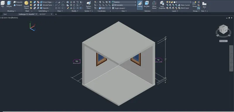
RESULT:- The given 3d isometric view of the building is drawn
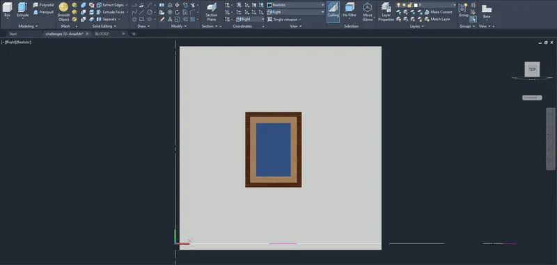
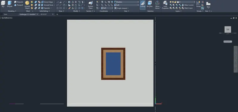
---------------------------X---------------------------
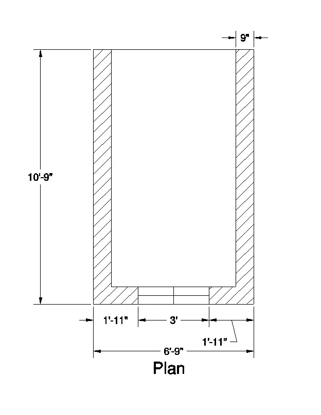
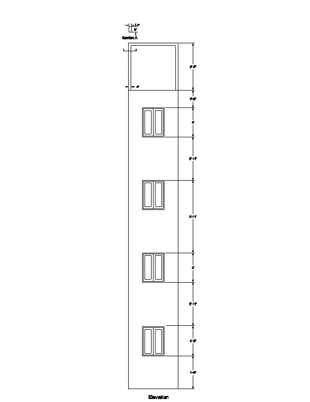
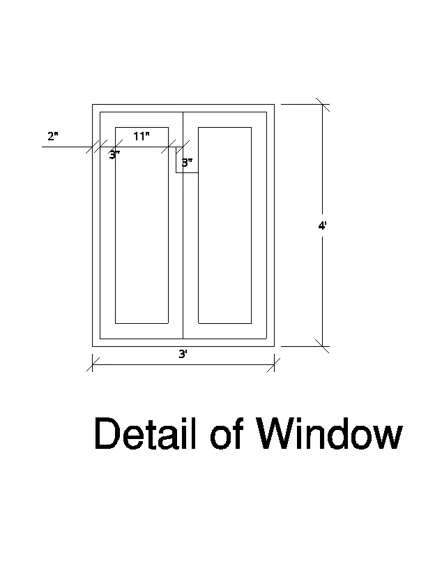
2. Create the 3D View of the Building Façade as given in the plan and elevation. Also, see the detail of the window.
AIM:-
-
To Create the 3D View of the Building Façade as given in the plan and elevation. Also, see the detail of the window.
PROCEDURE:-
- Open Autocad and set the units and limits
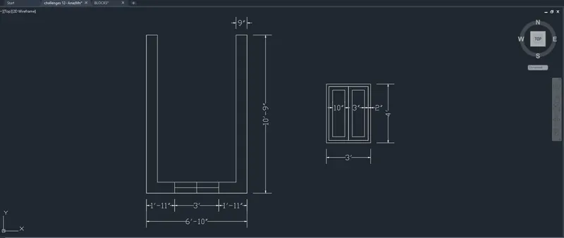
- Here first have to draw the rectangle using the rectangle command
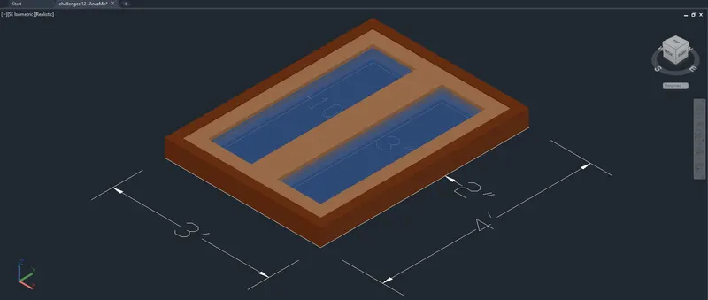
- to draw the window of size of 3' x 9".
- use the region command and select the objects, then press enter.
- Then the total objects will become one region.
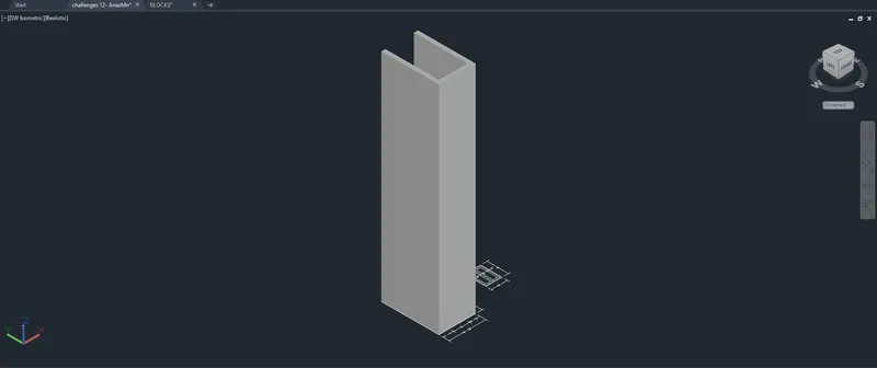
- Next, we need to extrude the plan using the extrude command, with a height of 40'-10".
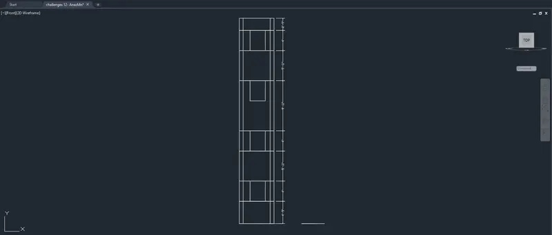
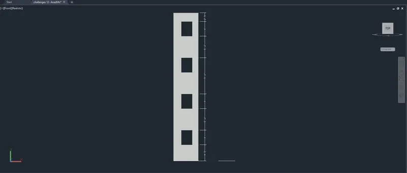
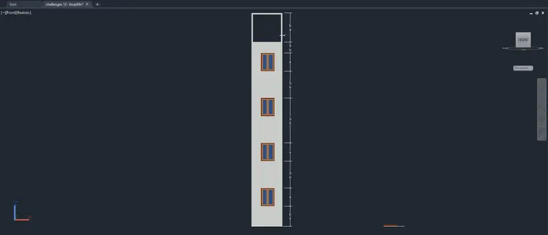
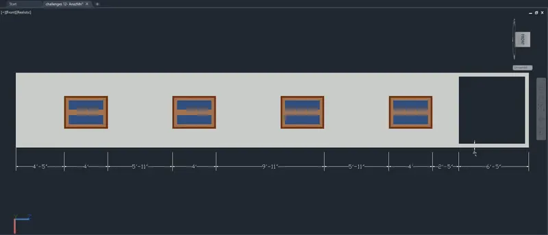
- Next, we need to subtract the four window portion vertically in a building facade with a distance of 5'-11" with a window size of 3' x 4'.
- Next, we use the union command and press enter.
- Next, we draw the window of the size 3'x 4' as shown in the below figure.
- We draw this window using the line command and extruded using the extrude command.
- Next, we use the 3dorbit command to view the front elevation as shown in the below figure.
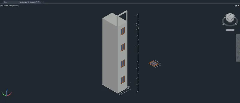
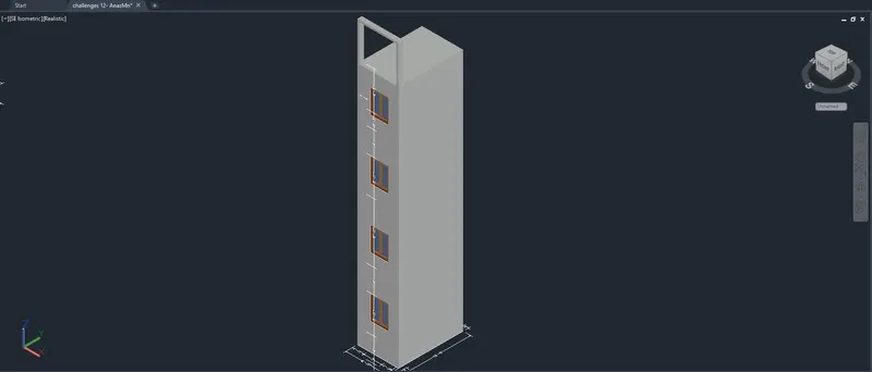
- Now put the building facade in the 3d isometric view using the 3dorbit command as shown in the below figure.
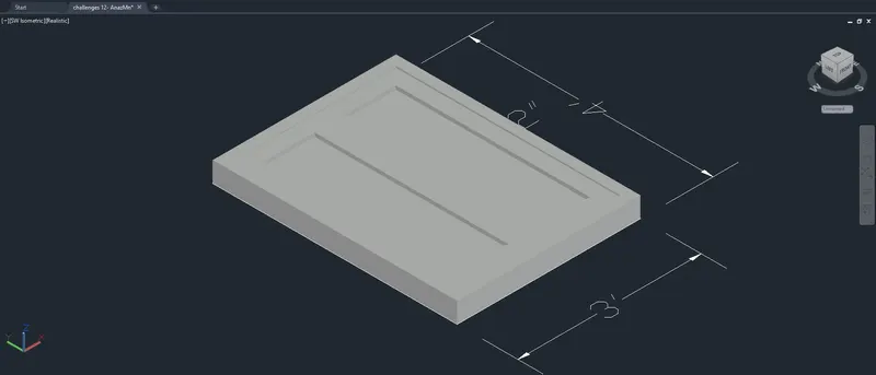
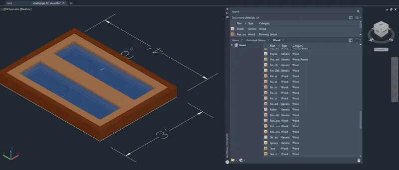
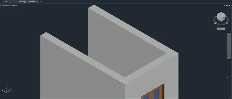
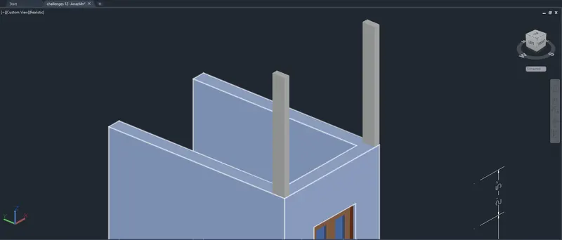
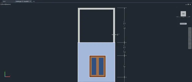
RESULT:- The given 3d isometric view of the building facade is drawn successfully in AutoCAD in a detailed manner.
---------------------------X---------------------------
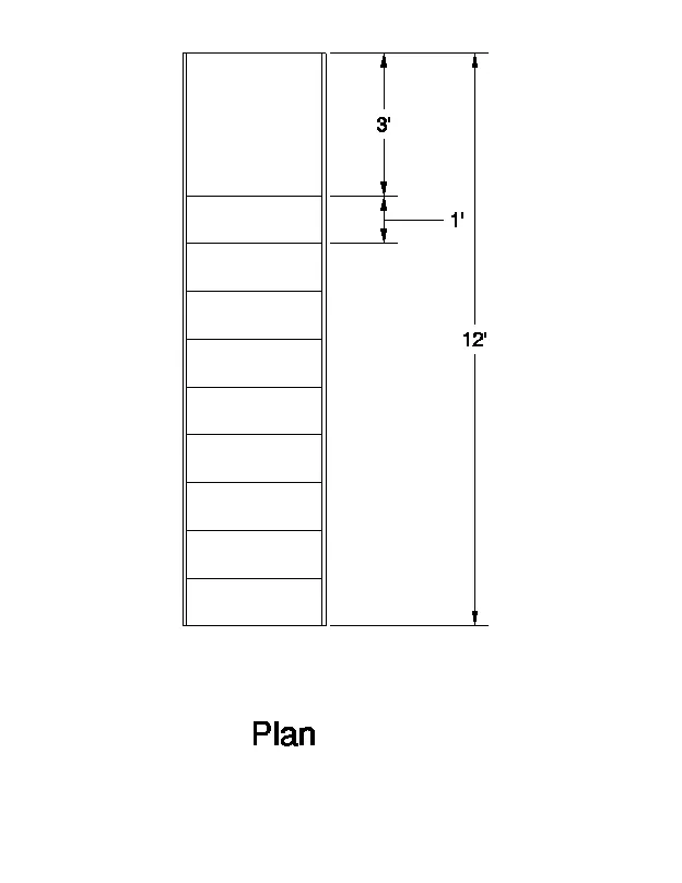
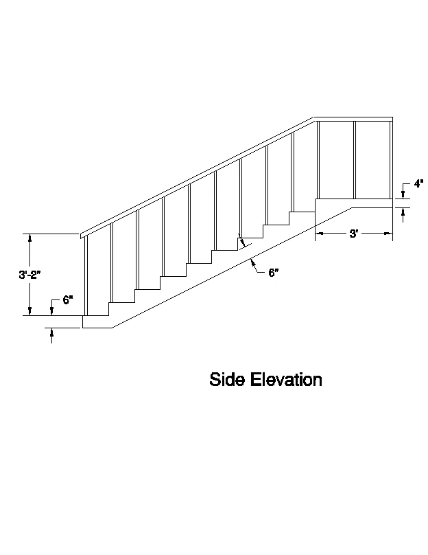
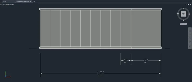
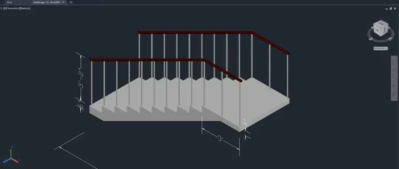
3. Create the isometric 3d view of a stair with a railing as shown in the plan and elevation. Assume the size of the balustrades and the handrails.
AIM:-
- To create the isometric 3d view of a stair with a railing as per the given plan and elevation
PROCEDURE:-
- Open the AutoCAD file
- Set the units, limits
- Change the view to the front
- Draw the stairs with a riser of 6" and tread of 1'
- Command extrude 4'
- Draw the railing using the circle command
- Command seep and select the object we get the railing
- Create a vertical post by circle command, extrude it
- Array the vertical post using the defined path
- Change the view to realistic
- Give the apt Materials
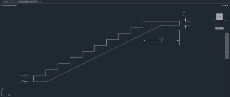
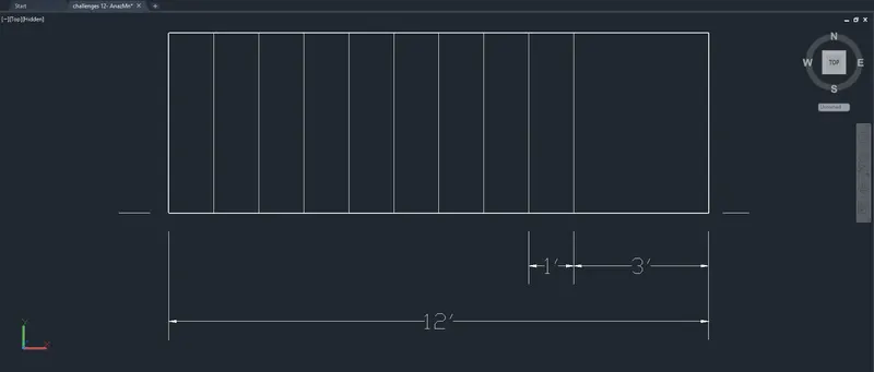
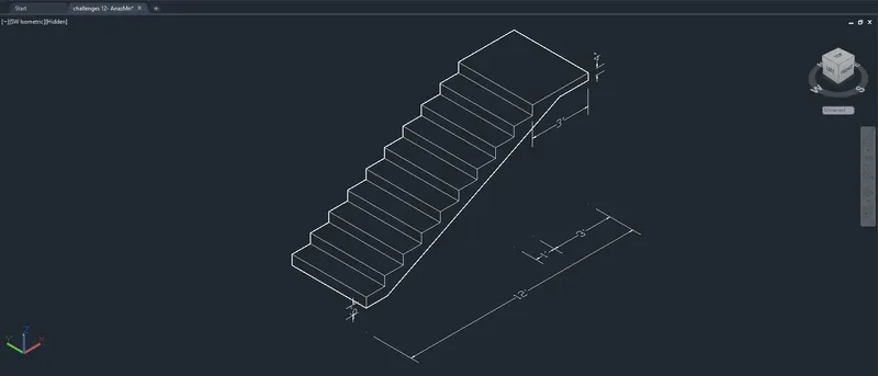
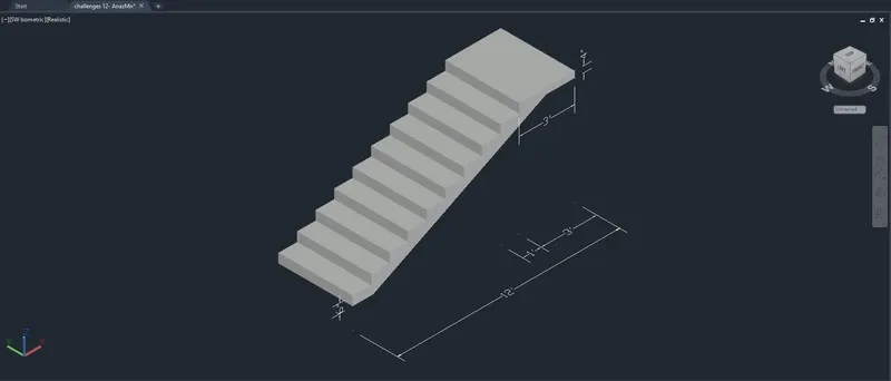
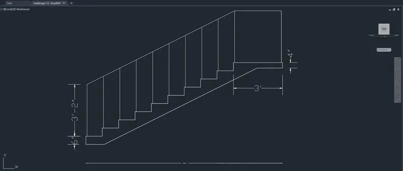
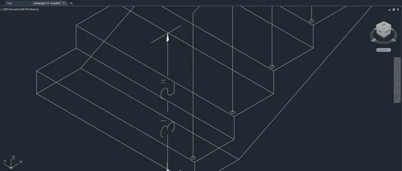
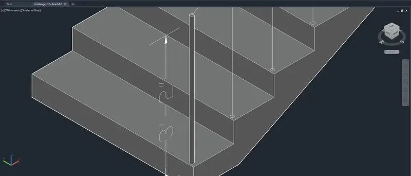
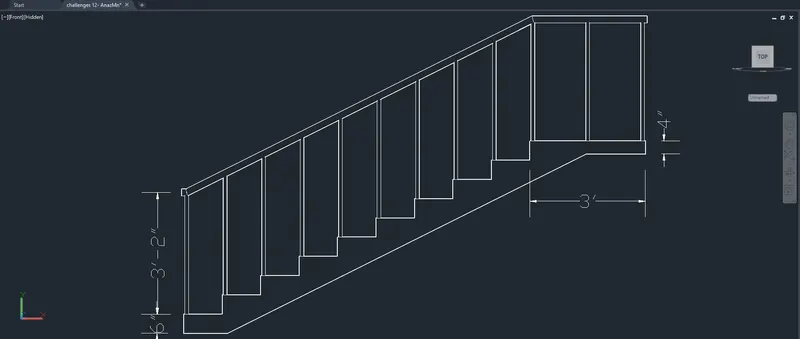
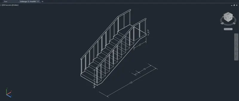
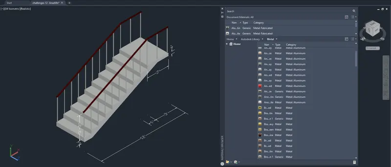
RESULT:- The given isometric view of the stair is drawn.
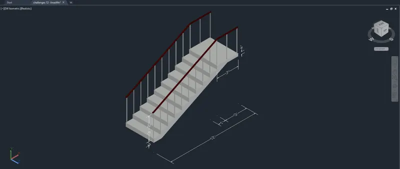
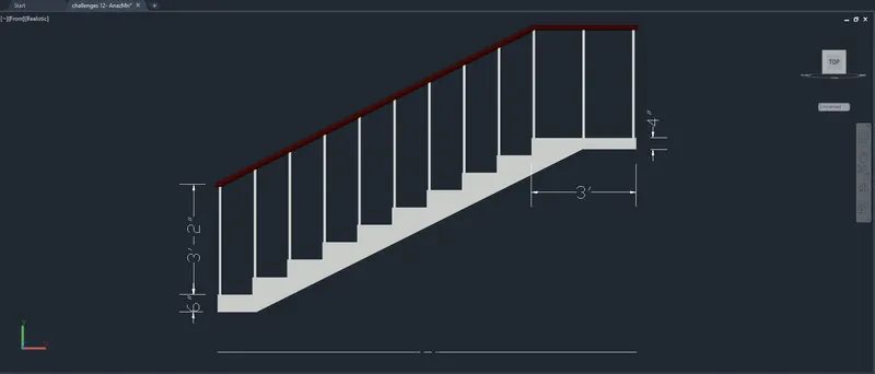
---------------------------X---------------------------
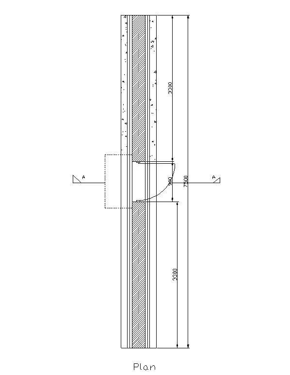
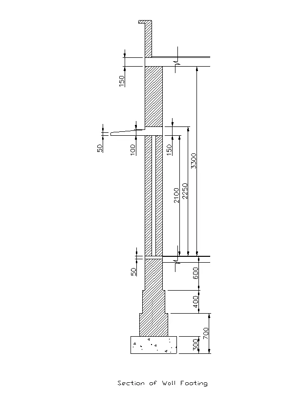
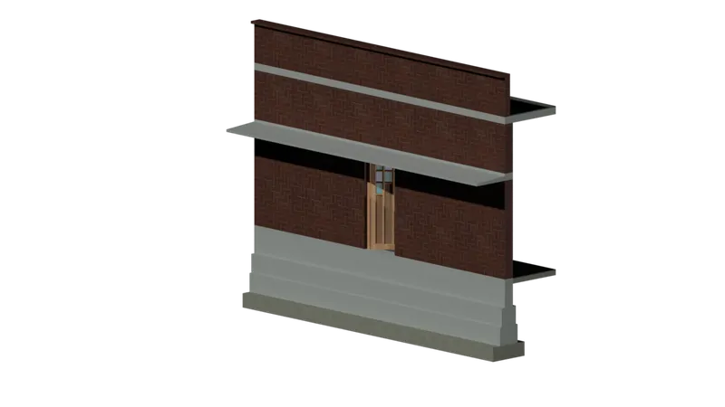
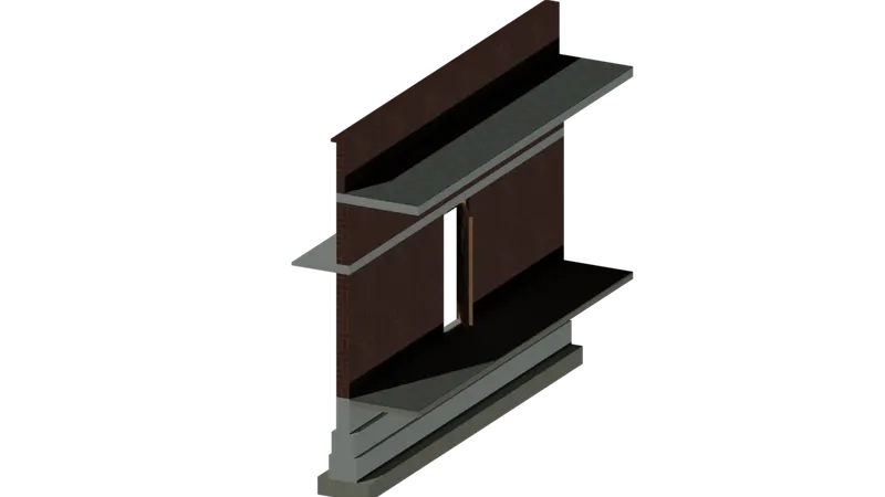
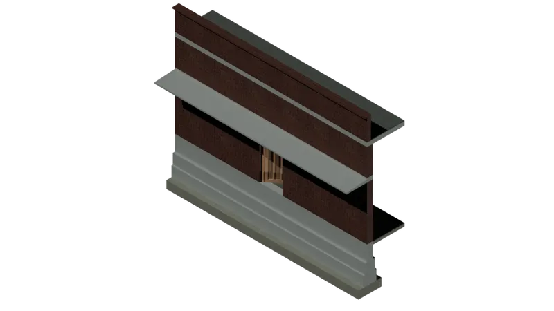
4. Create the 3D view of a Wall with spread footing. Create the Door opening only. Assume the size of the parapet and the coping. See the plans and elevation for the details. Also, create a rendered view of the model with materials as of your choice.
AIM:-
- To create the 3D view of a wall with spread footing and need to create the rendered view of the model
PROCEDURE:-
- Open the AutoCAD new file
- Set the units as decimal and the appropriate limits
- Provide the appropriate layers for working on it
- Draw the section of wall with spread footing with the given dimension
- Command extrude and given value of 7500
- Provide the layers for the wall with spread footing with different colors for different parts
- Provide different materials for the wall
- Select the camera and put it in the position
- Select the render option and then changes to the rendered view
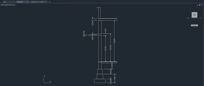

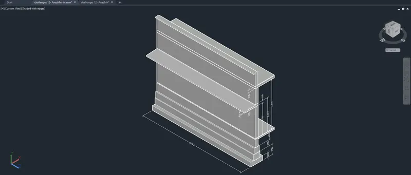
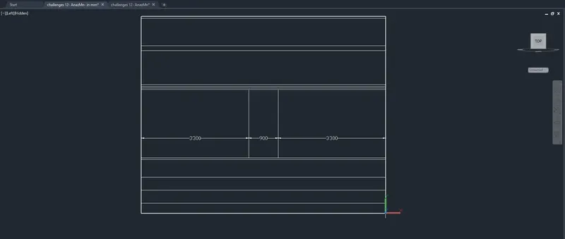
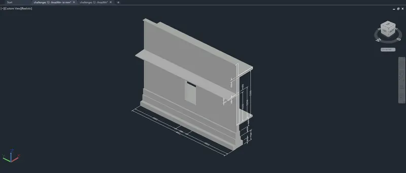
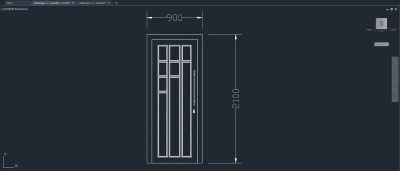
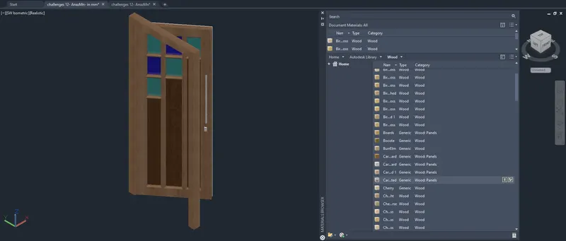
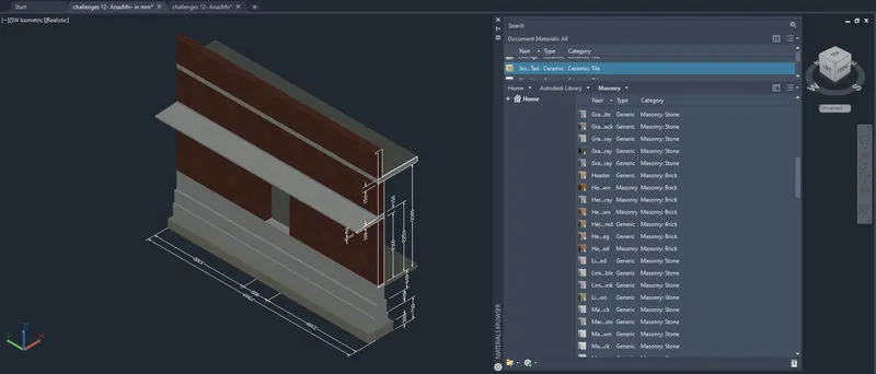
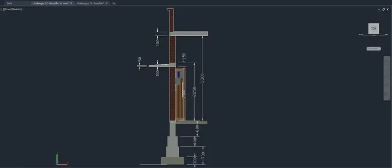
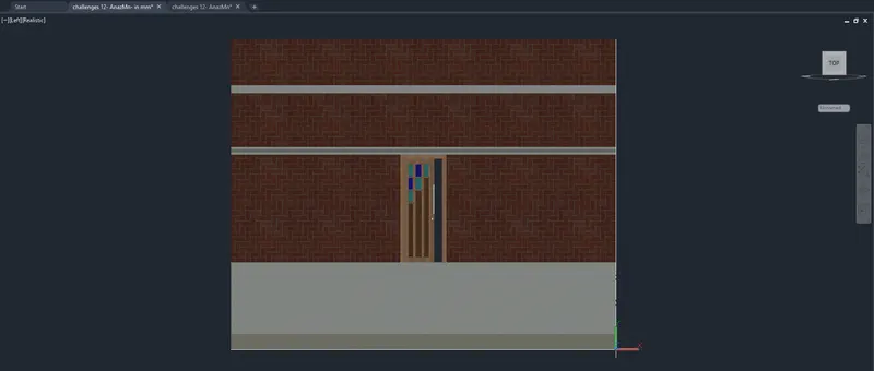
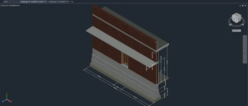
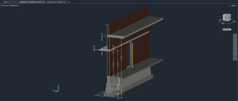
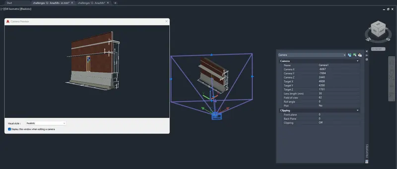
RESULT:- Created the 3D view and rendered view of the wall with spread footing
---------------------------X---------------------------