Creating 3D Isometric view of various structural elements in AutoCAD
AIM
- To draw the 3d isometric view of:
- Building given plan and elevation
- Facade of a building
- Stair
- Spread footing
COMMANDS USED:
- Extrude.
- Offset.
- UCS.
- Box.
- Union.
- Subtract.
- Move.
- 3d orbit.
- Boundary.
- Sweep.
- Render.
1).
3d isometric view of a building
Aim:
To create 3d isometric view of a building with plan and elevation.
Procedure:
Step 1:
Drawing the plan:
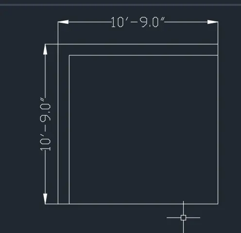
- In the top view,With line command, draw a line of 10'9" vertically and horizontally such that a L- shape walls formed.Offset 9" line from the two lines.
Step 2:
Draw the window:
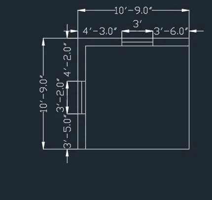
- Give offset of 4'2" from the corner of the wall.Again, give offset of 3'2" from that line for the window.
- Similarly on the other side also, offset 4'3" from the corner ,3' for the window.
Step:3
Making it 3d:
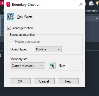
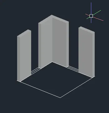
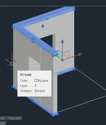
- Command"3do" for 3d orbit and orbit the view so that 3d view is seen.Now create a region in the wall area by command "BO" for boundary.Go to shaded view to see the boundary.
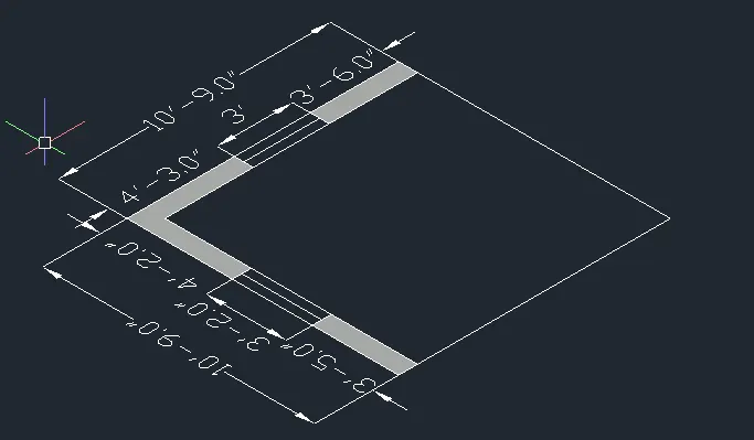
- Now extrude the region, giving a height of 10'. Command "EXTRUDE”, give height =10
Step 4:
Creating opening for windows:
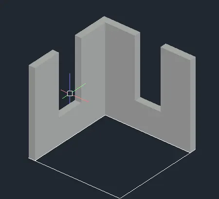
Draw a rectangle over the window portion.Extrude it to 3' i.e., to sill level.
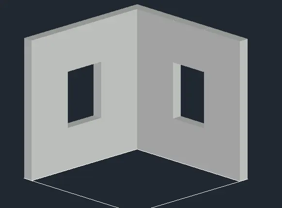
Similarly create a rectangle at the top.Extrude it downwards to a height of 3' from the top
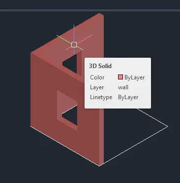
Create layer for walls and place it in wall layer
In the top view, by polyline create an outline of the plan .Then place it in the bottom by move command "M" @0,0, -10'.
Create a region by boundary.Extrude it downwards to a height of 4".Similarly create a polyline at top and extrude it to a height of 6".
Make it a union and place in wall layer
Step 5:
Creating elevation in 2D:
Elevation at A-A
Draw the elevation A from the plan in top view.Project the wall line from the plan and also the window lines.
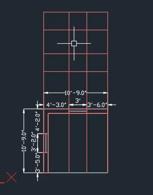
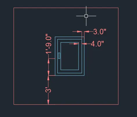
- Give the height as 10’, then offset lines of 3' from bottom and top to create window
- Then offset 3" for the frame and 4" for the mullion.
- Also offset 4' downwards for plinth and 6'upwards for the roof slab from the 10'.
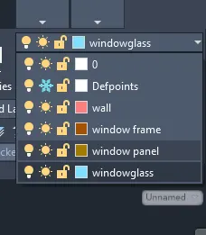
- Create different layers for frame, mullion and glass.
Step 6:
Creating 3d of elevation:
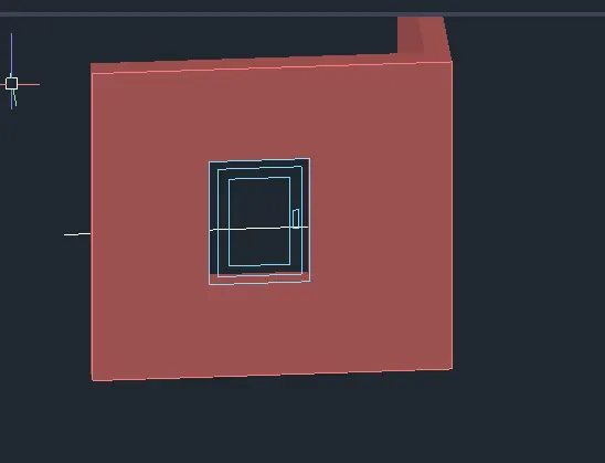
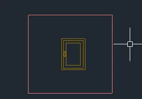
Place the 2d drawing in alignment to the 3d .Group the elevation by group command, so that all will be in a single selection.
By 3d rotate the image making it parallel to the 3d wall. select the axis then give angle as 90 degree.
Step 7:
Creating frame, mullion and glass of window.By "bo" command create a region for the frame.
Explode it and delete all other except window.If region is created fully, subtract, select larger region then smaller one.
Extrude the region, giving -3" value.
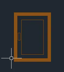
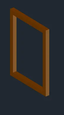
Similarlycreate region in window frame and extrude the frame 1.2"
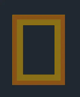
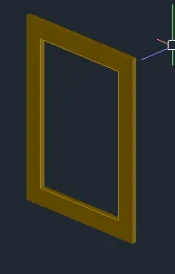
then create region in window glass and extrude it 0.6"
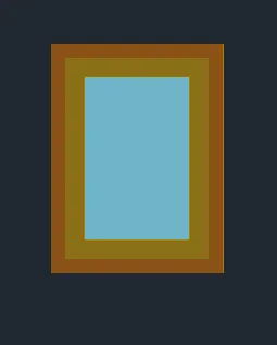
similarly create the section BB and make window
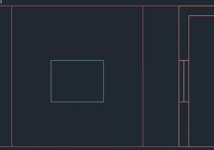
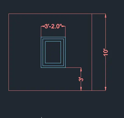
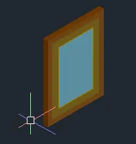
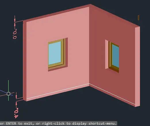
Move the 3d windows to the openings of the window created in 3d model.Make sure that the mullions are inside the frame and glass is inside the mullions.
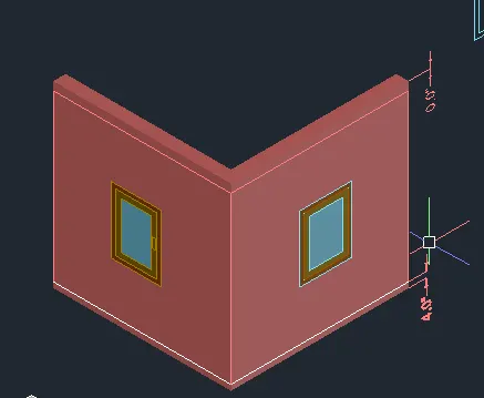
RESULT
2)
3d view of a building facade
Aim:
Creating 3d view of building facade
Procedure:
Step 1:
Creating the plan:
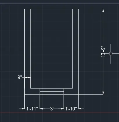
With rectangle command create a rectangle of 10'9" and 6'9".Offset 9" for the wall thickness.Create window of 3' width.
Step 2:
Extruding the height:
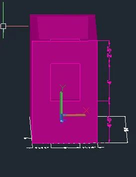
- As the sill level height is given as 4'6" and window height as 4’, and top height from the window is 2'5".
- Total height of one floor =2'5"+4'+4'6" =10'11"
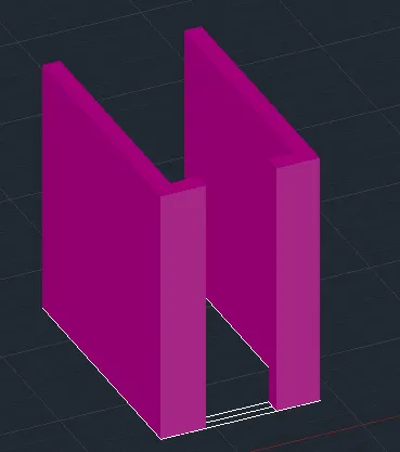
- Create a region in the part of wall for extrusion by command "BO".
- With extrude command extrude the created region giving a height of 10'-11".
Step 3:
Creating windows:
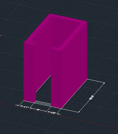
Create a rectangle at the bottom of the window position.
Extrude it to a height of 4'6".Similarly create a rectangle at the top and extrude 2'-5" downwards.
With union command, make all the walls in union.
Step 4:
Create construction line from the plan. Window detailing is done, 3" offset for frame and 4" for mullions.remaining glass area.
Create region in the frame of window by "BO" command, making frame as a layer.
Extrude -3" for the thickness of frame.
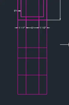
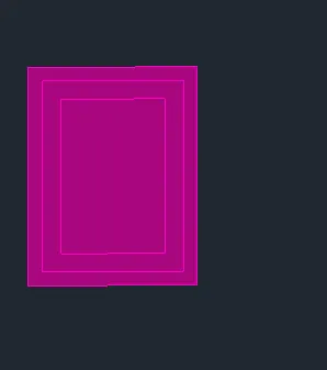
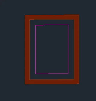
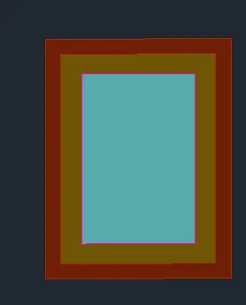
After region is done extrude panel frame and glass by 3"1.2"0.6" respectively
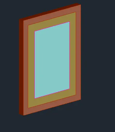
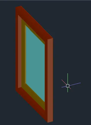
Then panel is moved inside for 0.5" and window glass is moved towards inside by 1"
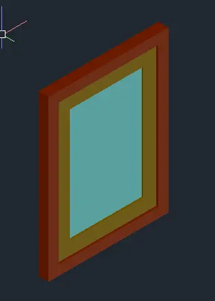
Move this object and place the window on the gap in 3d wall
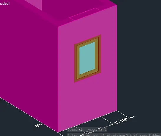
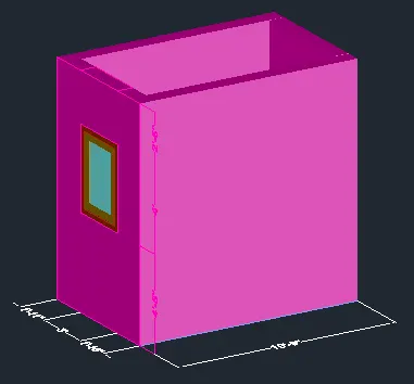
Step 6:
Creating floor
Go to top view and create a rectangle .Extrude it by 5".
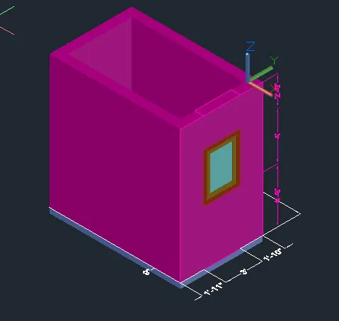
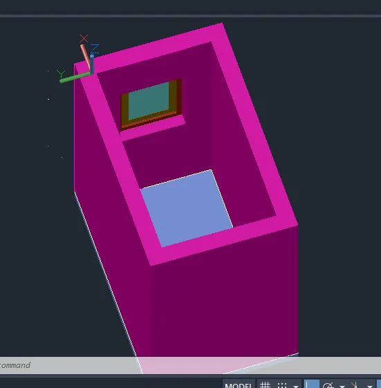
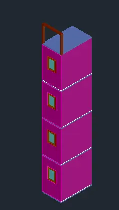
Group the created model and copy the created 1st floor on top.Copy the 4 floors as such
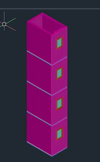
Step 7:
Creating top frame:
Type "UCS" as command and place the ucs on the top face of building.Draw a rectangle with dimensions 9" x 4".then freeze the wall layer
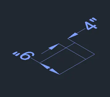
Extrude rectangle by 6'5".Copy it on the other side.
Again, create rectangle on top face.Extrude it by -4"
freezing of the wall layer
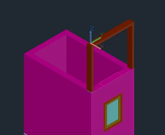
Create a roof on top by rectangle and extruding it.
Result
3)
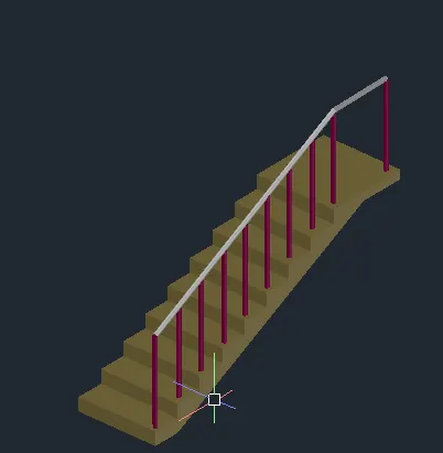
Creating isometric 3D view of stairs
Aim:
To create 3D view of stairs
Procedure:
Step 1:
Creating steps:
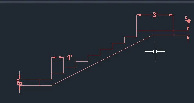
- With tread as 1' and riser as 6”, draw the steps in the top view 2d wireframe.Landing is 3' and the waist slab is 6" thickness.
- Join all these to form the section of the stair.
Step 2:
Extruding the stair:
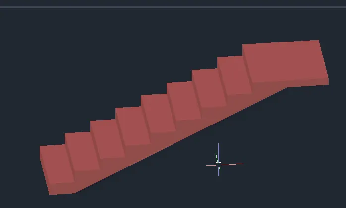
- Create a region by boundary command.With 3d orbit place the section in such a way that it is visible.
- Extrude 3' towards the side as 3' is taken as width of the stair.With 3d rotate -select x axis and give the value 90 degree.
Step:3
- Creating balustrades and handrails:
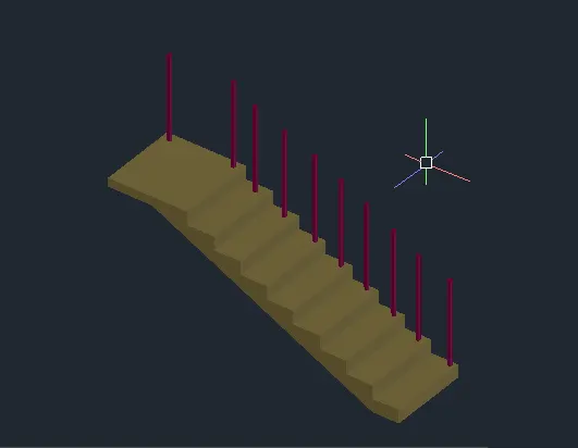
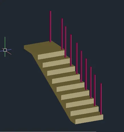
- Place the UCS on the tread and create a circle of diameter 2" . Extrude at a height 3'2".
- Copy it in all the treads and also in landing.
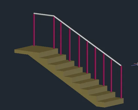
For handrails, create a polyline joining the balustrades by "3dpoly". 3d polyline.Create a circle of radius 2" and sweep it by selecting the circle and then the polyline.
Result
4).
3D View of a wall with spread footing
Aim:
To draw 3d view of wall with spread footing
Procedure:
Step 1:
Creating the plan - wall:
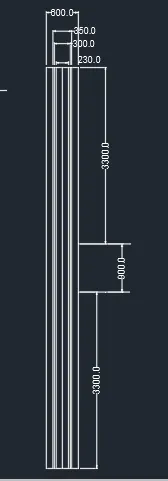
- With line command draw a vertical line of 7500mm and 230mm width
- Draw a centre line in wall and offset 150mm on both sides so that the total width is 300mm.
- From the 300mm line offset 25mm on both sides then the total width becomes 350mm.
- From the centre again offset 300mm on both sides, the total width is 600mm.
- Extend the horizontal line.Offset 3300mmfrom both the sides for the door opening of 900mm
Step 2 :
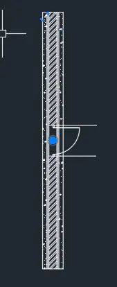
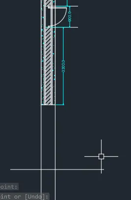
- Create door in the opening by circle and line.
- Hatch the wall, foundation with different hatches.ANS 132 for wall, Solid for footing, AR-CONC for bottom P.C.C.
Step 3:
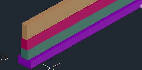
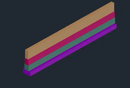
Making the 2d plan to 3d- footing R.C.C
With 3do make a suitable view.Make layers for footing-R.C.C, footing -steps, wall and door
Create a rectangle -profile on top of the plan of footing -R.C.C. place in the respective layer and copy it.Create region by boundary command.
Extrude it by 300mm.
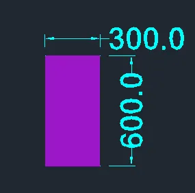
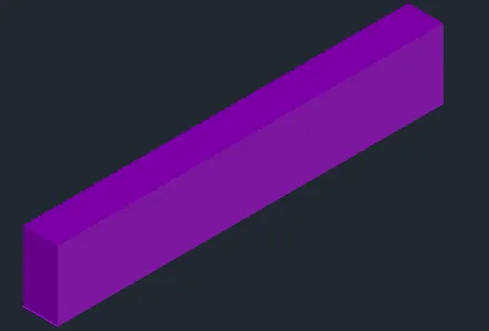
using construction line remaining foundation plan create
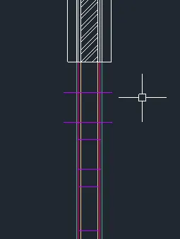
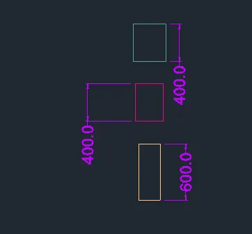
extrude the foundation by 7500mm.and place the layer one above other.
Step 6:
Creating wall:
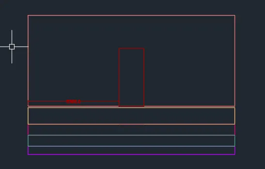
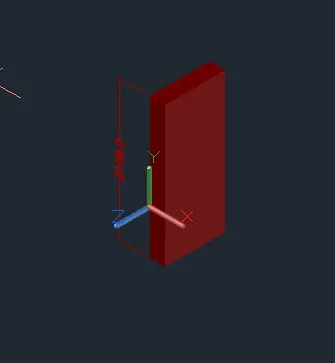
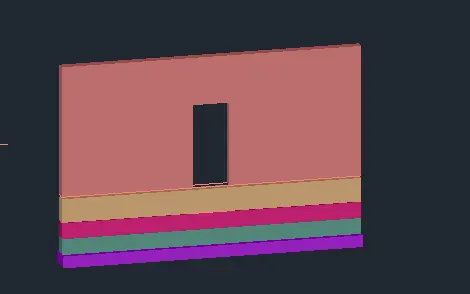
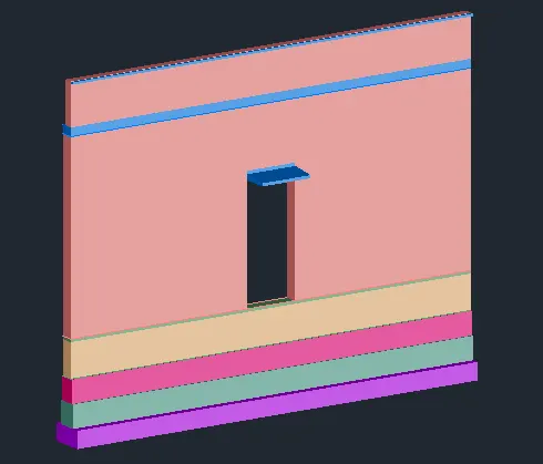
Now create profile for wall on both sides of door.Copy it and place it in 3 d model and extrude at a height of 3300mm.and a rectangle of size 900x2100mm is created in the frond view of the wall at a distance of 3300mm from the left end .then extrude the door.then from solid edit select substract select the wall first then door.
Step 7:
Creating lintel beam:
select ucs on place the curser to the door face wall then draw a rectangle of 230 x 150.then extrude the lintel beam by 900mm.
Step 8:
Creating Shade:
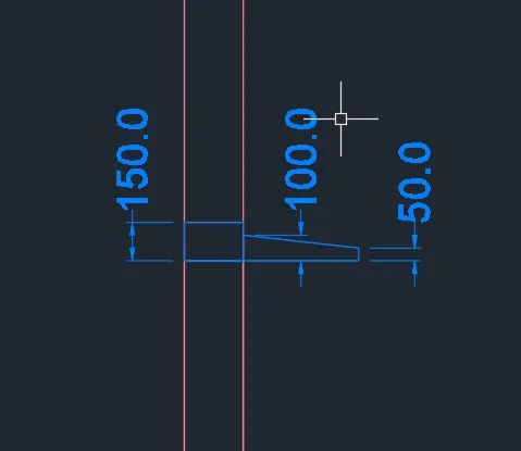
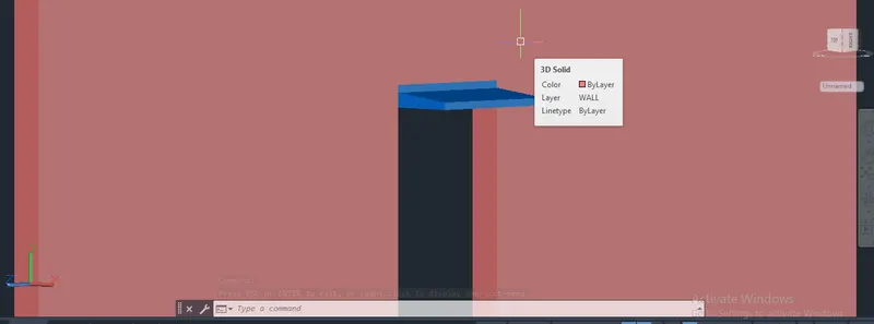
top view on then draw shade 100mm in the side of lintel and 50mm other side.then isometric view on extrude the shade by 900mm.
Step 9:
Creating top slab:
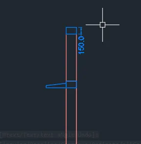
open top view then create arectangle 230 x 150mm then extrude throut the wall.
Step 10:
Creating parapet and coping:
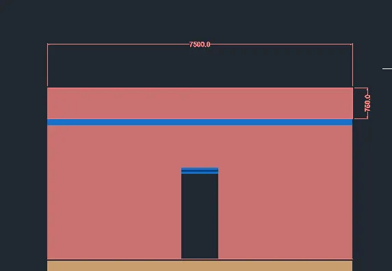
- Create parapet of width 150mm and height 750mm.Create a rectangle of 7500mm and 150mm on top of the 3d model.
- Extrude it by 750mm.
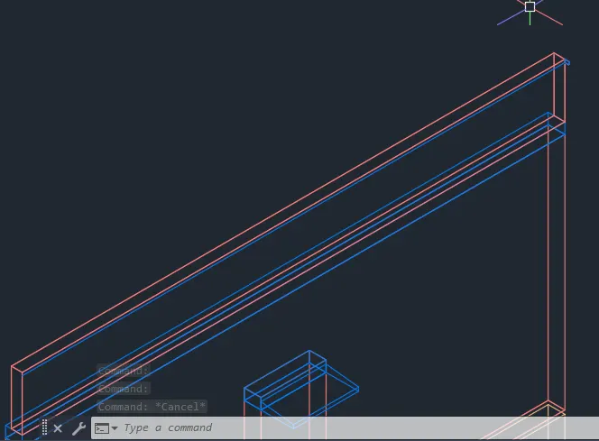
- For coping in the side view place, the ucs and draw 40mm width line from the parapet with projection of 60mm.Create a region by bo command
- Draw a line on top.
- Use sweep option, select the projection and then the line.
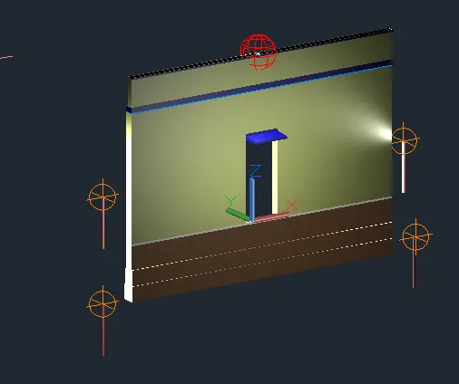
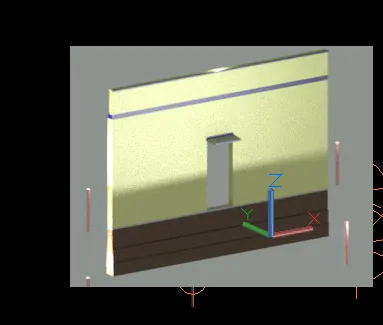
Step 12:
Rendered view:
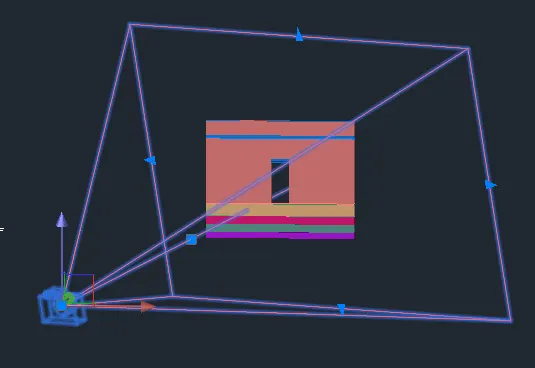
Go to visualise tab,camera select plce it 1500 hight and lence size 35mm.
Go to visualise tab, select material browser.
For foundation, select a stone.For wall, select from paint.
For floor, select from flooring.Select each object and give assign to selection
keep shadows on.Create a cylinder and give distant light.
Then click on render or command "RR".
Result
RESULT:
- 3d view of a building is created.
- 3d view of Facade of a building is created.
- 3d isometric view of stair is created.
- 3d view and rendered view of Spread footing is created.