Creating 3D Isometric view of various structural elements in AutoCAD
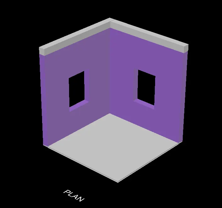
1. Create a 3D Isometric View of the building with plan and elevation given.
Answer:
Aim: To create a 3D Isometric View of a building with plan and elevation.
Commands Used:
- Line
- Rectangle
- Dimlinear
- UCS
- Region
- Extrude
- Substract
- Box
- Units
- Dimstyle
- 3D face
- 3Dorbit
- Explode
- Hide
- Move
- Copy
- Dist
- Solidedit
- 3D Mirror
- Union
- Boundary
- Erase
- Trim
- 3D rotate
Procedure:
1. Launch AutoCAD
2. Start over in the startup settings choose Imperial (Feet and Inches)
3. In AutoCAD, switch the workspace setting from "drafting and annotation" to "3D Modeling."
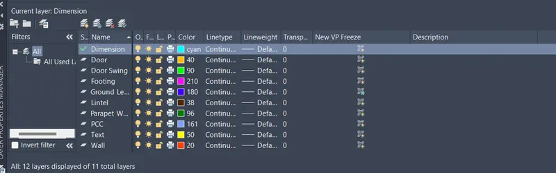
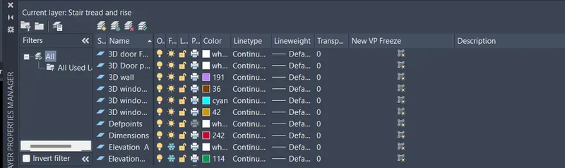
4. Create new layers by clicking on new layer in the Layer Properties window or by doing a right-click on any layer and choosing new layer.
5. Change the current layer to 3D wall
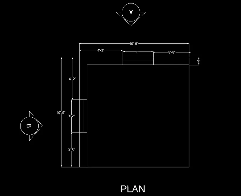
6. Create a rectangle of dimensions 10'9"x 10'9"at any point on the screen
7. Offset the rectangle to inside to distance of 9"as wall thickness
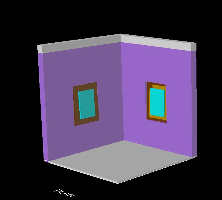
8. Delete the left and bottom lines and extend them to the edges as shown in the figure.
9. Change the current layer to 3D window frame.
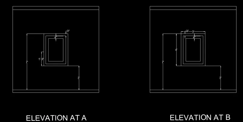
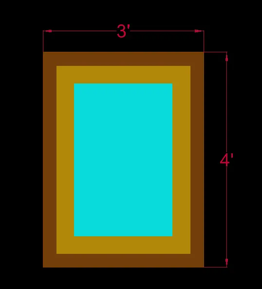
10. Draw the window with dimension 3'2"at top and 3'on right side as shown in the figure.
11. Change the view to 3D by clicking at the home button of view cube
12. Set the UCS as world
13. Create the boundaries for the wall using BO command
14. Extrude the boundaries created to total height of 10'10"
15. Select the wa;; and use the group command to group them together.
16. Draw rectangles at both windows and change them to boundaries
17. Extrude both the rectangle drawn to height of 3'4"as shown in the figure.
18. Draw rectangle at top of window openings and change them to boundaries.
19. Type UCS and click on face and select the face having 3'2"wide window
20. Draw a rectangle from bottom part of window with dimension @3'2", 4'
21. Change the UCS back to world
22. Extrude the rectangle drawn at top side to top edge of window
23. Group all the wall components together.
24. Change the current layer to 3D window frame
25. Type UCS and click on face and select the face having 3'wide window.
26. Draw a rectangle of dimension @3',4'
27. Offset the rectangle to inside to distance of 3"
28. Start the boundary command and click on pick points
29. Click inside the window frame area press enter
30. Start SUBSTRACT select the bigger region and then select the smaller region to substract.
31. Follow the same procedure for all the three boxes as shown in figure.
32. Change the current layer to 3D window million.
33. Click the boundary command and click on pick points.
34. Take substract command, select the smaller glass region to substract bigger rectangle(Mulion)
35. Change the current layer 3D window glass
36. Start the boundary command click on points click on glass area and enter.
37. All the layers are extruded to give window projection look as shown in the figure.
38. Use the 3Dorbit command to see the difference views of given figure.
39. Place the window drawn in the elevation.
Result: The given 3D Isometric View of the building with plan and elevation is sketched as shown below.
AutoCAD Result:
2. Create the 3D View of the Building Façade as given in the plan and elevation. Also, see the detail of the window.
Answer:
Aim: To create the 3D view of the building Facade in the plan and elevation.
Commands Used:
- Line
- Rectangle
- Dimlinear
- UCS
- Region
- Extrude
- Substract
- Box
- Units
- Dimstyle
- 3D face
- 3Dorbit
- Explode
- Hide
- Move
- Copy
- Dist
- Solidedit
- 3D Mirror
- Union
- Boundary
- Erase
- Trim
- 3D rotate
- Plan
Procedure:
1. Creating a 2D plan view
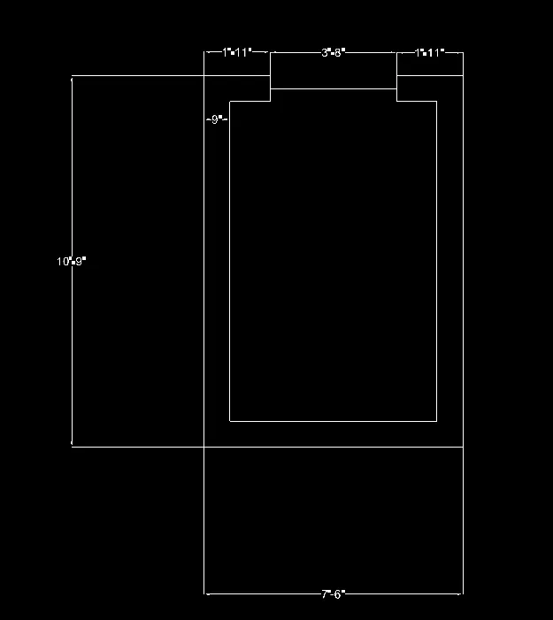
2. Take rectangle command of dimension 6'9"x 10'9"
3. offset the rectangle 9"as thickness of wall.
4. explode the rectangle rectangle
5. delete the top lines and extend the edges.
6. Alter the 3D Window Frame layer currently active.
7. Make the window opening 3' wide, as illustrated in the illustration.
8. With a dimension layer, more dimensions are drawn.
Making a 3D view
9. By clicking the home button on the view cube, the view can be changed to 3D.
Make UCS the world.
10. With the 'BO' command, define the walls' perimeters.
11. Extrude the drawn lines until they reach a height of 40'10".
12. Use the group command to select every wall and group them all together
13. delete the window lines
14. Create a boundary and expand the perimeter to 4'6"height.
15. Draw a rectangle top of the window opening using rectangle command.
16. Create a region for the rectangle.
17. Extrude the window 1'3"downward as shown in the figure.
18. Window with 4"width create a layer for the window frame to current.
19. Ucs select the face, draw a rectangle of 3'and 4', and adjust the rectangle.
20. Next change the current layer to 3D mulion and create a boundary click points.
21. click inside area and press enter, substract the bigger rect with smaller one.
22. Next change the current layer to 3D Glass and create a boundary click points.
23. click inside area and press enter, substract the bigger rect with smaller one.
24. Extrude the window projections.
25. Place the windows in elevation. and create the top part of the building as shown in the figure.
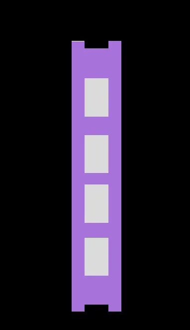
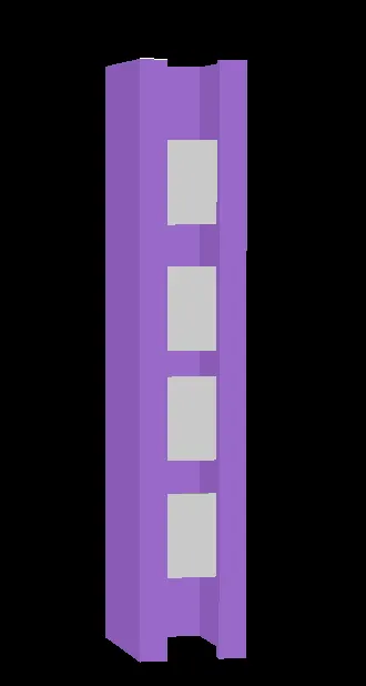
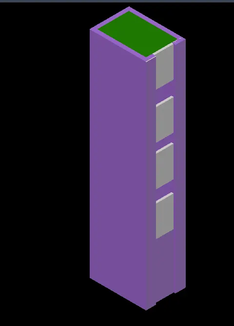
Result: The given 3D Isometric View of the building facade with plan and elevation is sketched as shown below.
AutoCAD Result:
3. Create the ismoteric 3d view of a stair with railing as shown in the plan and elevation. Assume the size of the balustrades and the hand rails.
Answer:
Aim: To create the isometric 3D view of a Stair with railing
Commands Used:
- Line
- Rectangle
- Dimlinear
- UCS
- Region
- Extrude
- Box
- Units
- Dimstyle
- 3D face
- 3Dorbit
- Explode
- Move
- Copy
- Dist
- Solidedit
- 3D Mirror
- Union
- Boundary
- Erase
- Trim
- 3D rotate
- Plan
Procedure:
1. Change the layers set as per staircase
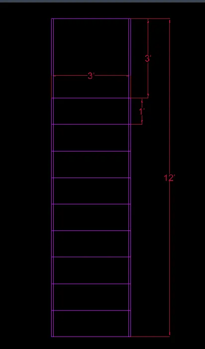
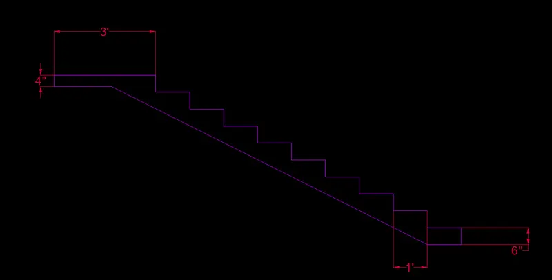
2. Draw a rectangle 3'x 12'explode rectangle
3. Offset the rectangle 1" twelve times.
4. Change the plan to 3D, set the UCS as right.
5. Line command draw vertical line of length 6"
6. Draw horizontal line of length 1'repeat the same procedure for 12 times to draw 12 steps.
7. Draw the landing of 3'and 1'bottom step
8. Draw a line 6"at the top right edge of landing
9. Draw a of 1'6"backwards and draw the slab joining line
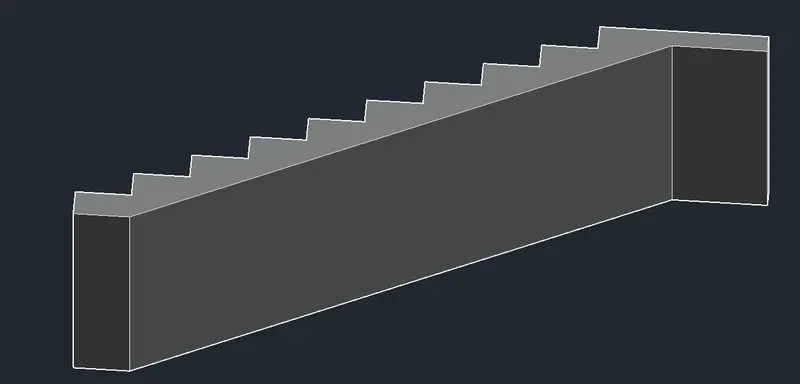
10. Change the view to 3D set the UCS as world
11. Set the view as relastic, extrude the side distance 3'
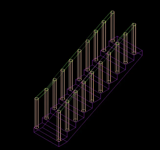
12. To draw handrail, change the current layer to handrail, draw circle of 1"with 2"offset from top right.
13. Change the circle into region extrude to height of 3'.
14. use copy command and copy the hand rail, sides
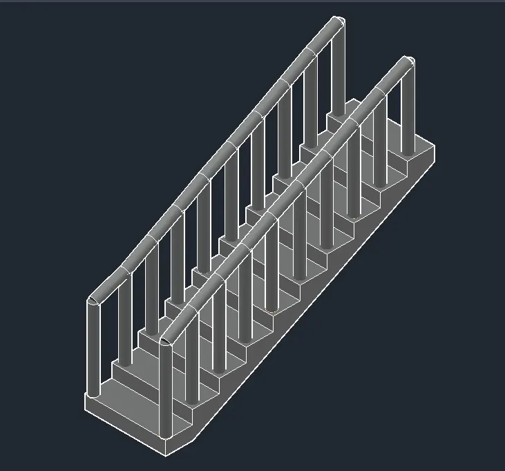
15. Draw a circle of diameter 2"on top of first hand rail and use sweep command select the circle and select polyline path of sweep.
16. copy the same for other side. 3D orbit to view.
Result: The given 3D Isometric View of a stair with railing with plan and elevation is sketched as shown below.
AutoCAD Result:

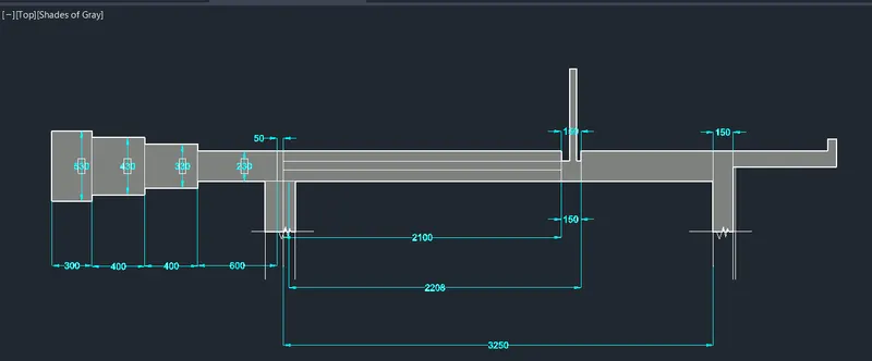
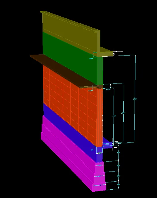
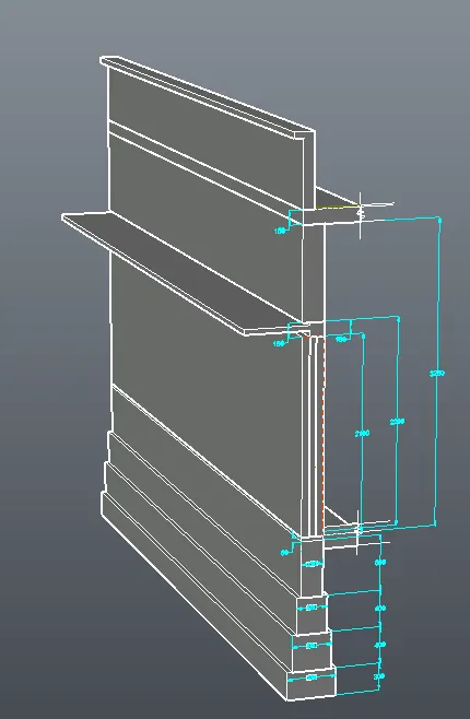
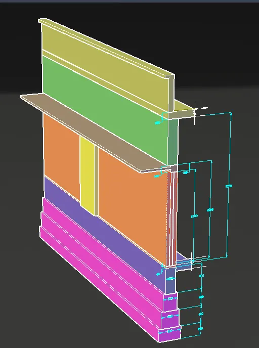
4. Create the 3D view of a Wall with spread footing . Create the Door opening only. Assume the size of the parpaet and the coping. See the plans and elevation for the details. Also, create a rendered view of the model with materials as of your choice.
Answer:
Aim: To create the 3D view of a wall with spreading footing and to create a rendeed view of the model.
Commands Used:
- Line
- Rectangle
- Dimlinear
- UCS
- Region
- Extrude
- Substract
- Units
- Dimstyle
- 3D face
- 3Dorbit
- Explode
- Hide
- Move
- Copy
- Dist
- Solidedit
- 3D Mirror
- Union
- Boundary
- Erase
- Trim
- 3D rotate
- Plan
Procedure:
1. Change the plan to 2D and change the layers for spread footings
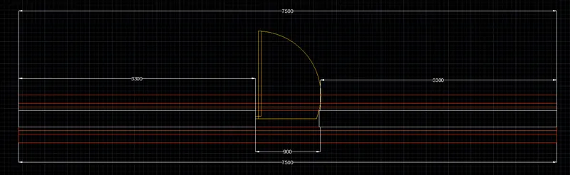
2. Draw a rectangle of dimension 670 x 7500 and give offset of 120mm and then 50mm twice offset.
3. explode all the offset rectangles, delete top and bottom of outer rectangle.
4. extend the rectangles.
5. Create a Door using block, Rectangle 50 x 100 another rect of 50 x 50mm line edge 850mm draw a arc to swing the door. Add door lock
6. convert the door to block.
7. Change the current layer to G.L draw a central length.
8. offset the line 25mm bottom line
9. again offset the bottom line to 100mm
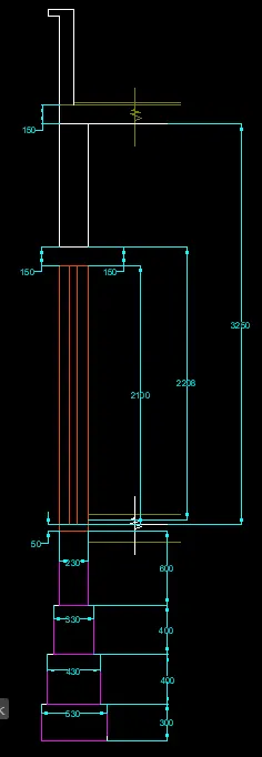
10. Change the current layer to wall draw a rectangle of dimensions 230 x 3300 from the top left edges of ground level.
11. Draw a roof of thickness 150mm and parapet wall of height 600mm
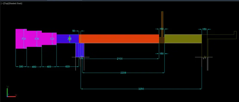
12. For the footing select the layers draw the rectangle of dimension 230 x 600 below the floor level, 330 x 400 for first level, 430 x 400 for the second level and 670 x 300 as third level.
13. Trim all unwanted lines. create a door and give the shade to door.
14. create each boundary and extrude the created boundaries.
15. Go for the rendering add materials and use Cam command to take screenshot.
Result: The given 3D Isometric View of a wall with spread footing is sketched as shown below.
AutoCAD Result: