Creating 3D Isometric view of various structural elements in AutoCAD
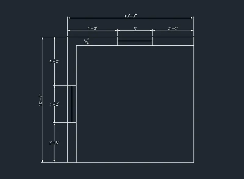
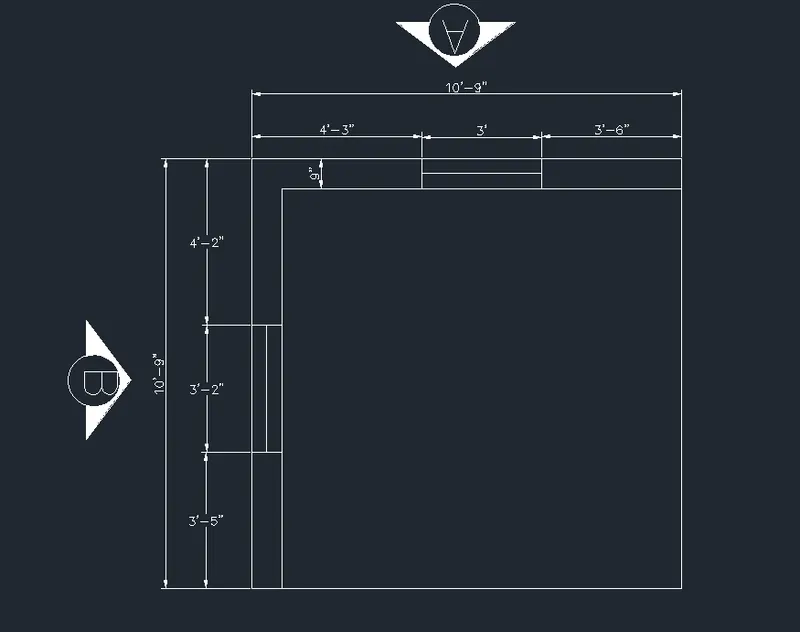
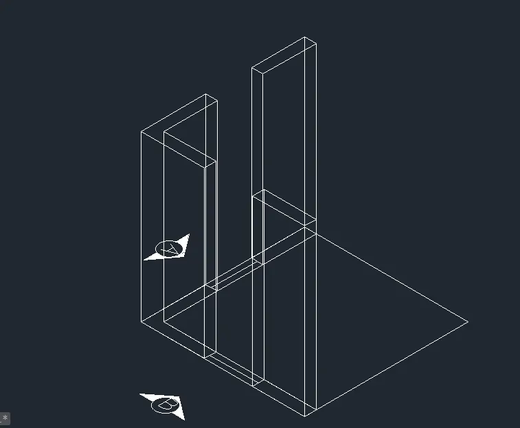
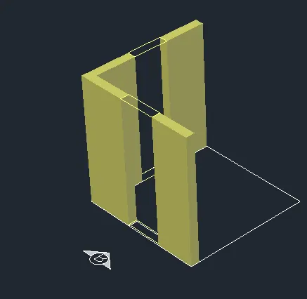
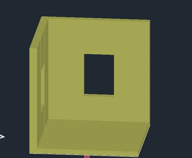
1. Create a 3D Isometric View of the building with plan and elevation given.
Aim:
- To Draw the 3D Isometric view of the building as shown in figure
Introduction:
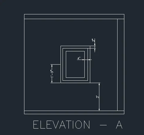
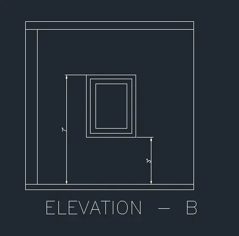
- A plan view of wall two elevation of windows on both sides are given and they are to be converted into a 3D model
- The height of floor is given as 10' and height of window from the floor is 3'
- The basic render workflow is to attach materials to the 3D objects of a model, place user defined lights
- Add a background and start the render with the render command.
Procedure:
- Initially open the AUTOCAD and go to 3D modeling
- Then set the units as engineering and imperial (inches)
- Open gird and snap setting
- Set the spacing and major lines
- We have to take a rectangle using the command of size 10'9"
- Next was to draw the window of size 3' x 9"
- Next, we use the region command and select objects, then press enter
- we get total object will come as one region
- Type UCS and click on face and select the face having 3' wide window
- Draw a rectangle from bottom part of window with dimensions @3'-4'
- Draw a rectangle from bottom part of window with dimension as @3'2"-4'
- Next, we use the region command and select the object and press enter
- Group them all the objects
- Enter boundary command and click on pick points
- Click inside the window frame area and press enter
- Next use SUBTRACT command
- Select the Bigger region then select smaller region to subtract
- Change the current layer to 3D window
- Click inside the window to create Milon area and press enter
- Again, use Subtract command
- Select the bigger region and select the smaller glass region
- Change the current layer to 3D view
- Click inside the window glass area and press enter to set the boundary
- All dimension is in feet and inches
- Text and dimensions with respective layers
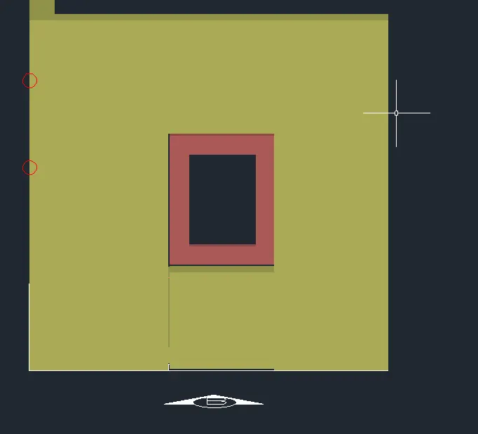
- Finally, the result as shown in the figure.
Result:
2. Create the 3D View of the Building Façade as given in the plan and elevation. Also, see the details of the window.
Aim:
- To draw the 3D building Facade as given in the plan and elevation
Introduction:
- A plan view of wall and two elevation views, one is of window details and second is of floor level elevation.
- One window opening on front side is given with details regarding the frame dimensions
- The height of floor is given as 9'11"
- Four building with similar dimensions is created in 3D view
- Height of the window from the floor level of each floor is given as 4'6"
- Commands are used as
- Line
- Rectangle
- UCS
- Dim linear
- Extrude
- Region
- Boundary
- 3D face
- 3D orbit
- Realistic
- Copy
- Move
- Union
- Plan
Procedure:
- Open AUTOCAD select new one
- Set the limits and DIMS
- Type UN in command and press enter
- Set the unit as Engineering and precision as inches
- Change the workspace set as 3D modeling
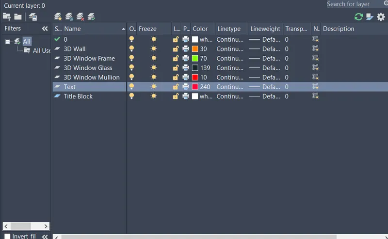
- Open layer properties and create new layer to all the layers
- Layers are shown in the figure
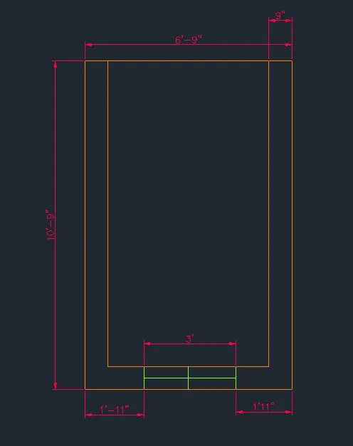
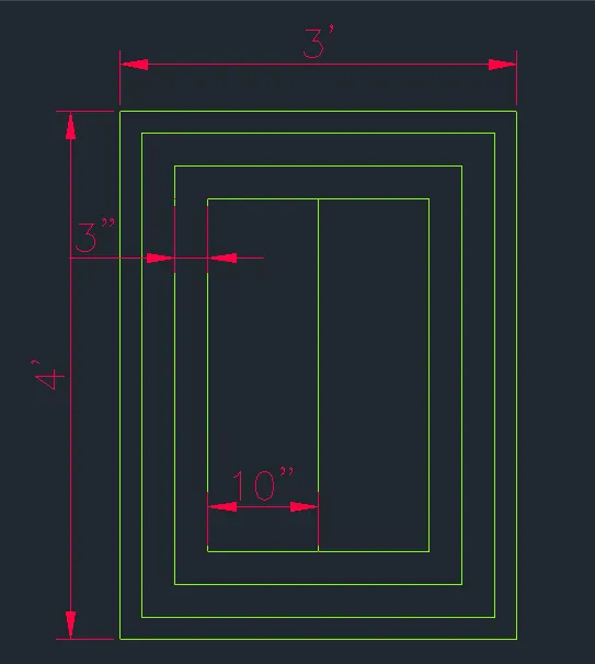
- Create the rectangle as 6'9" x 10'9" at any point
- Offset 9" the rectangle inside as wall thickness
- Explode the rectangles drawn
- Delete the top and bottom lines and extend that.
- Create the window opening of dimension 3' wide
- Mention the dimensions as respectively
- Set the UCS world
- Set the view style control as Shaded
- Command BO for create walls
- Extrude the walls height was 10'9"
- Select all the wall and use group them
- Delete the window lines
- Create a boundary region over the window lines
- Extrude the boundary to a height was 4'6"
- Draw a rectangle on top of the window opening using rectangle command
- Change the rectangle into a region
- Extrude the region to distance of 1'3"
- Change the layer to 3D window frame
- Enter UCS and click on face and select face 3' wide window
- Draw a rectangle of dimension @3'4"
- Offset the rectangle to inside distance of2"
- And again offset 3" inside the rectangle
- Trim all the unwanted lines
- Command BO and select the frames for region
- Command Subtract Select the bigger region then smaller region to sub
- Command BO Click on pick point
- Click inside the Mailon area and press enter
- And subtract them
- Command BO create the region
- Click inside the window glass area and press enter
- Group all the objects
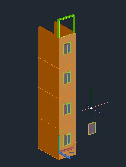
- Copy the block having 4' height window and place it 3 time
- Create the top part of the drawing using 4" wall with height 6'5" top angle
- Create a boundary wall
- Extrude the wall 9"
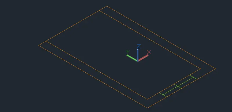
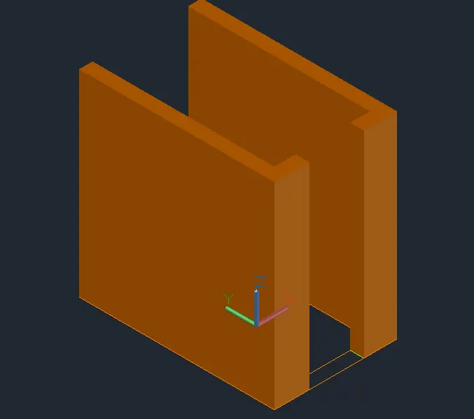
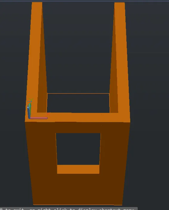
- Finally, the 3D modeling as shown in figure
- The result consists of different views such as Front, Top, SW, NE isometric views
Result:
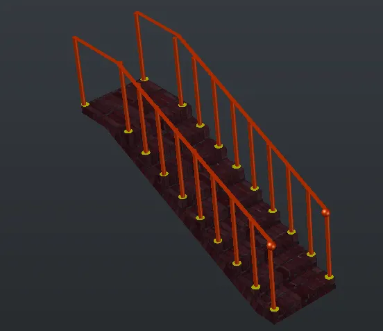
3. Create the isometrics 3d view of a stair with railing as shown in the plan and elevation. Assume the size of the balustrades and the hand rails.
Aim:
- To create the isometric 3D view of a stair with railing as shown in the plan and elevation.
Introduction:
- An isometric drawing is a 3D representation of an object, room, building, stairs or design on a 2D surface
- This is due to the fact that the fore shortening of the axes is equal
- In an isometric drawing the object appears as if it is being viewed from above from one corner, with the axes being set out from this corner point.
Procedure:
- Open the AUTOCAD click the new one
- Then set the limits and DIMS
- Type UN command set as engineering Precision as 0
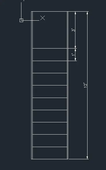
- Command rectangle to create a first step of stairs
- And offset Side edges 1"
- Offset for Thread as 1' multiple 9 times and landing 3'
- Then use dim linear and texts respectively
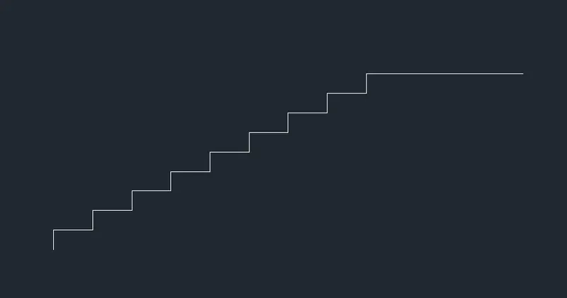
- Change the view front to create the side elevation of stairs
- Take line command riser as6" and thread is 1'
- Copy up to midland
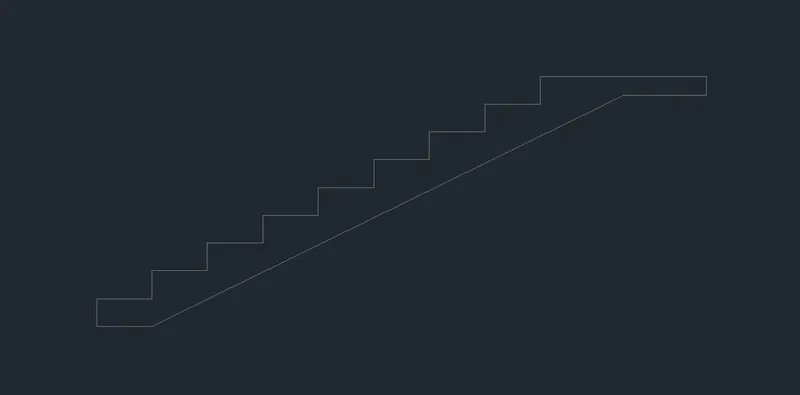
- Now the portion is change to region
- And EXTRUDE it distance of 4"
- Create the handrails Using a command of Circle and Polyline
- And sweep the objects 2"
- Now mention the dimensions
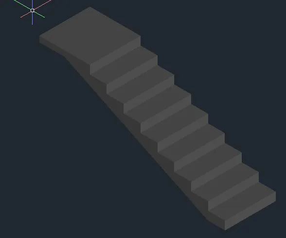
- We have to develop the isometric view of this staircase
- For this we have to hide the text and dimensions
- Then change the view to Sw
- Finally, the result as shown below in the figure
Result:
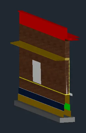
4. Create the 3D view of a Wall with spread footing. Create the Door opening only. Assume the size of the parapet and the coping. See the plans and elevation for the details. Also, create a rendered view of the model with materials as of your choice.
Aim:
- To create the 3D view of a wall with spread footing
Introduction:
- An isometric drawing is a 3D representation of an object, room, building, stairs or design on a 2D surface
- One of the defining characteristics of an isometric drawing, compared to other types of 3D representation, is that the final image is not distorted.
- In an isometric drawing the object appears as if it is being viewed from above from one corner, with the axes being set out from this corner point.
Procedure:
- Open the AUTOCAD click the new one
- Then set the limits and DIMS
- Type UN command set as engineering Precision as 0
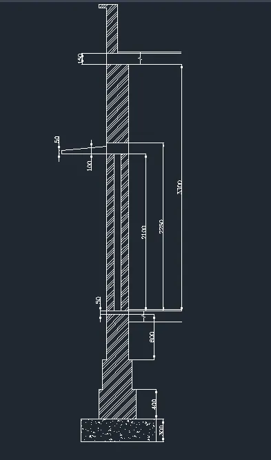
- draw the plan of wall with spread footing with given dimension as shown in the figure
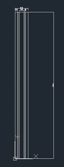
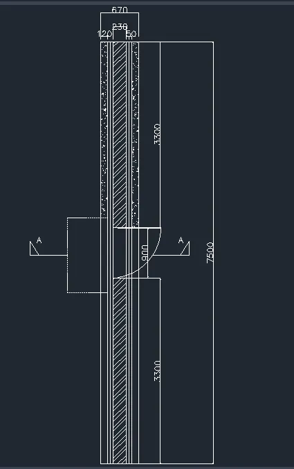
- Create the layers as shown in the figure
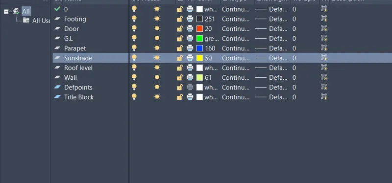
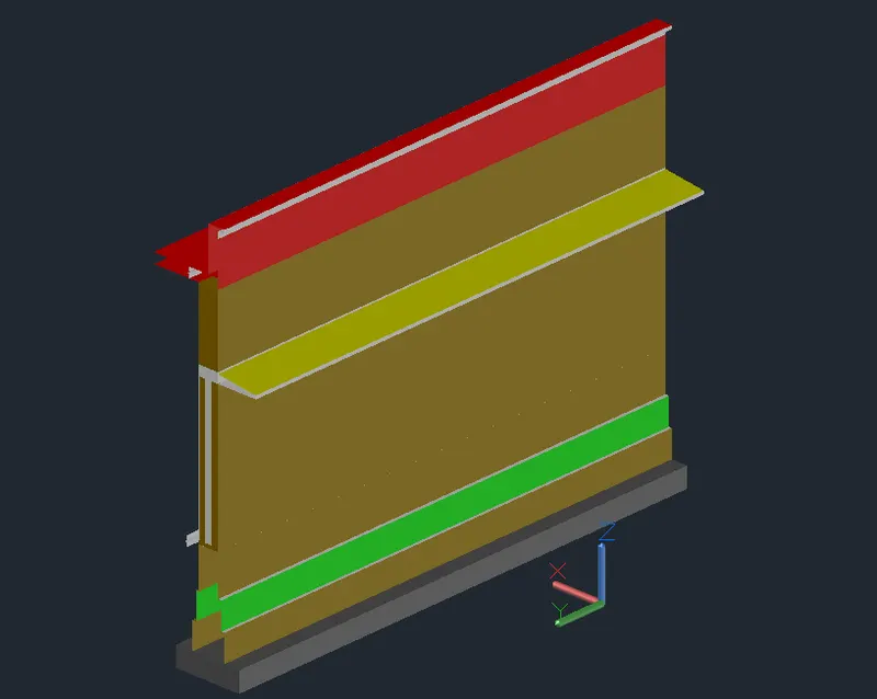
- Next, we draw the 3D isometric view of the wall with spread footing
- Using the command Extrude
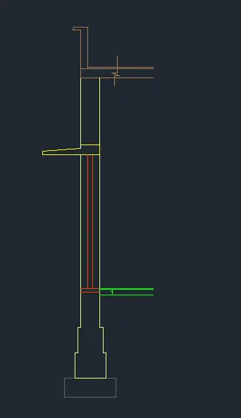
- Next provide the layers for the wall with spread footing with defend colors for different parts as shown in the figure
Result:
- The 3D view of a wall with spread footing and created a rendered view of the model with material successfully in the AUTOCAD