Creating 3D Isometric view of various structural elements in AutoCAD
C1
Aim and introduction:To Create a 3D Isometric View of the building with plan and elevation given.
Procedure:
Steps:
- Using the Line command draw the plan in top and the elevation in right view.
- Create a layers for different elements.
- Offset is used.
- Make the lines as a region for extrusion.
- Extrude the regioned area
- MOVE command is used for the moment of components
- Then viewed in a SW isometric.
- Material browser used for the surface.
- And then viewed in different views like 2D wireframe, Hidden,Conceptual and Realistic.
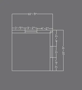
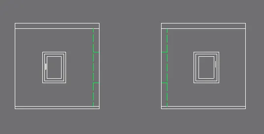
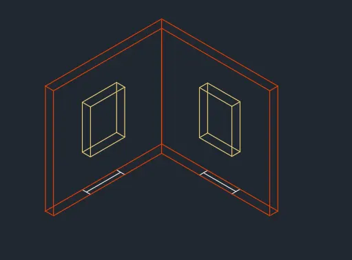
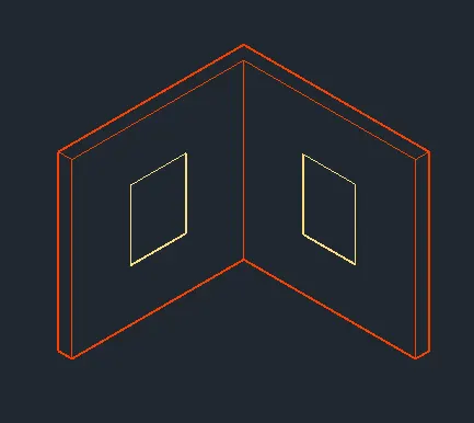
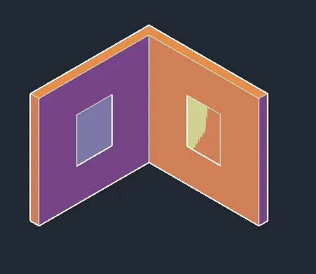
Results: Creation of a 3D Isometric View of the building with plan and elevation given using autocad 3D modelling tools.
C2
Aim and introduction:To Create the 3D View of the Building Façade as given in the plan and elevation
Procedure:
Steps:
- Using the Line command draw the plan in top and the elevation in right view.
- Create a layers for different elements.
- Offset is used.
- Make the lines as a region for extrusion.
- Extrude the regioned area
- MOVE command is used for the moment of components
- Then viewed in a SW isometric.
- Material browser used for the surface.
- And then viewed in different views like 2D wireframe, Hidden,Conceptual and Realistic.
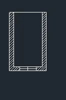
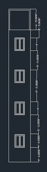
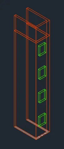
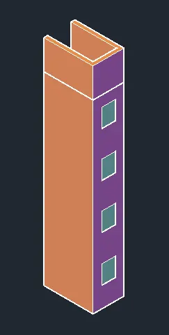
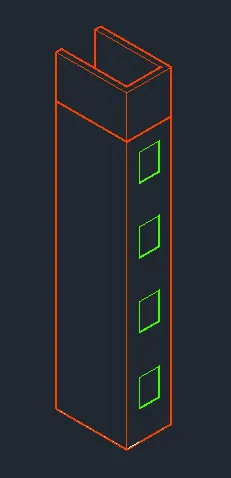
Results:Creation of the 3D View of the Building Façade as given in the plan and elevation using autocad 3D modelling tools.
C3
Aim and introduction:To Create the ismoteric 3d view of a stair with railing as shown in the plan and elevation
Procedure:
Steps:
- Using the Line command draw the plan in top and the elevation in right view.
- Create a layers for different elements.
- Offset is used.
- Make the lines as a region for extrusion.
- Extrude the regioned area
- MOVE command is used for the moment of components
- Then viewed in a SW isometric.
- Material browser used for the surface.
- And then viewed in different views like 2D wireframe, Hidden,Conceptual and Realistic.
- RENDER is used for the rendering.
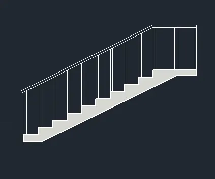
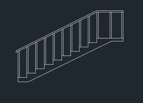
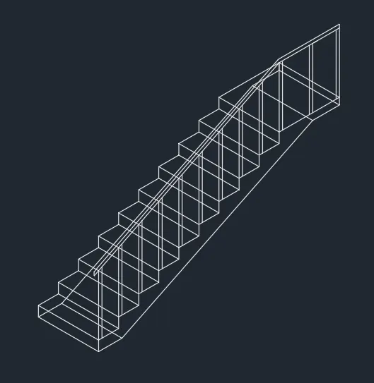
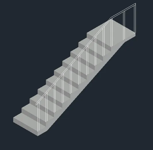
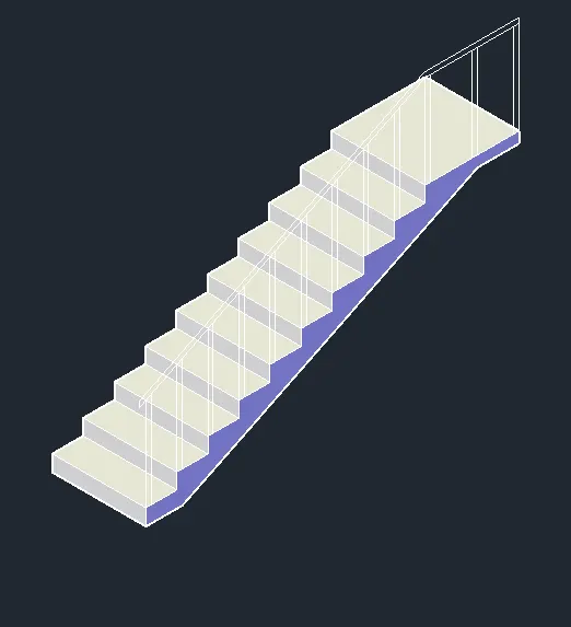
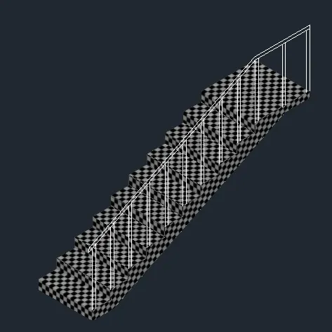
Results:Creation of the ismoteric 3d view of a stair with railing as shown in the plan and elevation using autocad 3D modelling tools.
C4
Aim and introduction:To Create the 3D view of a Wall with spread footing . Create the Door opening only Also,To create a rendered view of the model with materials .
Procedure:
Steps:
- Using the Line command draw the plan in top and the elevation in right view.
- Create a layers for different elements.
- Offset is used.
- Make the lines as a region for extrusion.
- Extrude the regioned area
- MOVE command is used for the moment of components
- Then viewed in a SW isometric.
- Material browser used for the surface.
- And then viewed in different views like 2D wireframe, Hidden,Conceptual and Realistic.
- RENDER is used for the rendering.
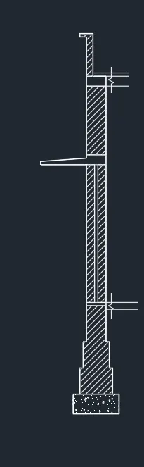
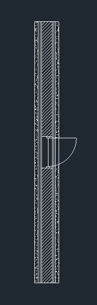
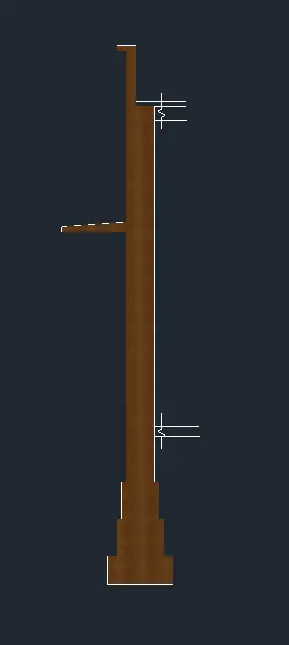
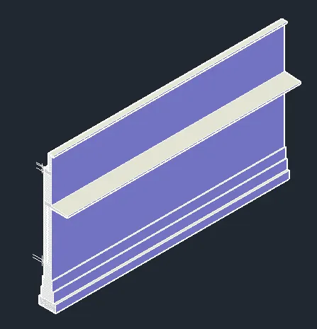
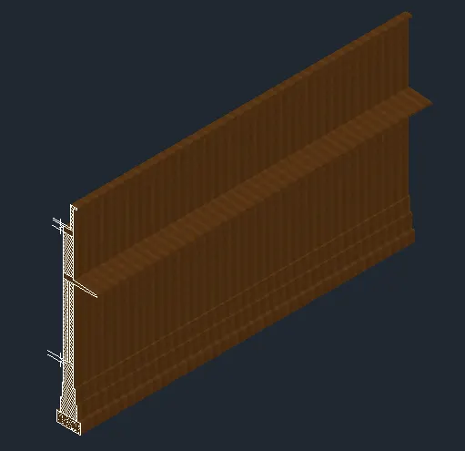
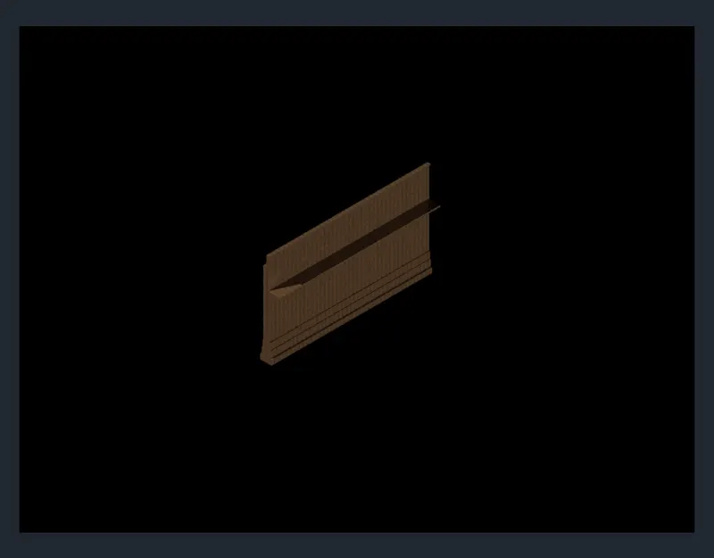
Results:Creation of the 3D view of a Wall with spread footing . Create the Door opening only Also,To create a rendered view of the model with materials using autocad 3D modelling tools.