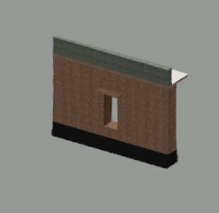
Creating 3D Isometric view of various structural elements in AutoCAD
1.AIM:
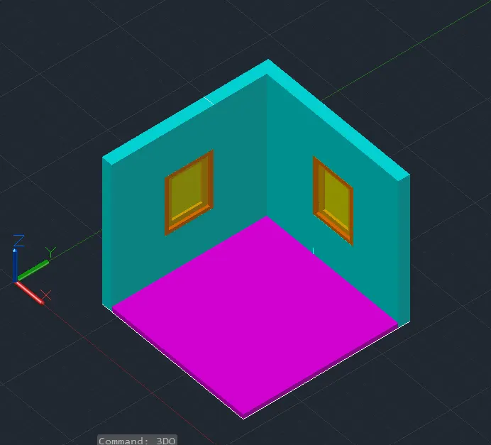
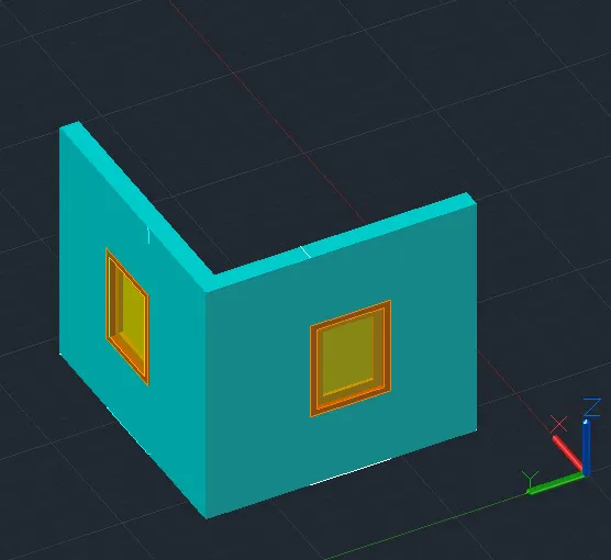
⦁ To create a 3D isometric view of the given building with the plan and elevation.
COMMANDS USED:
⦁ line
⦁ rectangle
⦁ UCS
⦁ region
⦁ extrude
⦁ substract
⦁ 3D Orbit
⦁ union
⦁ plan
⦁ erase.
PROCEDURE:
⦁ Set the units in engineering and in inches.
⦁ set the min and max. limits.
⦁ draw the rectangle using the command.
⦁ we have to draw the windows of the required sizes.
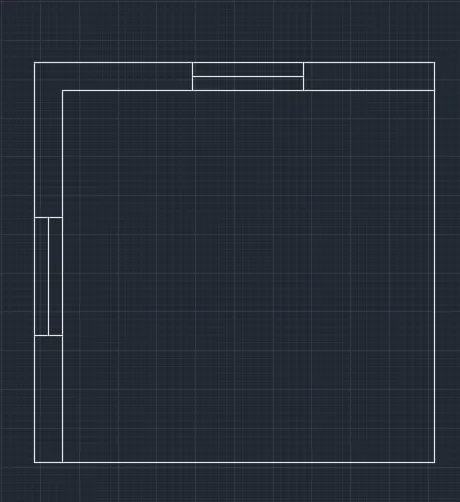
⦁ after we have to draw the windows and offset the window to provide a frame, panel and glass.
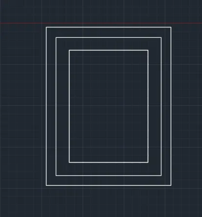
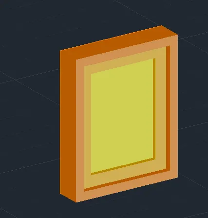
⦁ create a layer for the frame, panel and glass and give the different colour for them.
⦁ use the command extrude and extrude the window.
⦁ create the layer for the wall and for the floor
⦁ extrude the wall and substract the window portion using the substract command.
⦁ attach the windows to the wall.
⦁ next we use the 3D orbit command to create the different views of figure.
RESULT:
⦁ The given 3D isometric view of the building with the plan and elevation is drawn by using the autocad.
2. AIM:
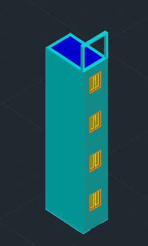
⦁ To create the 3D view of the facade as given in the plan and elevation and need to create the window using the given dimensions.
COMMANDS USED:
⦁ line
⦁ rectangle
⦁ UCS
⦁ region
⦁ extrude
⦁ substract
⦁ 3D Orbit
⦁ union
⦁ plan
⦁ erase.
PROCEDURE:
⦁ Set the units in engineering and in inches.
⦁ set the min and max. limits.
⦁ draw the rectangle using the command.
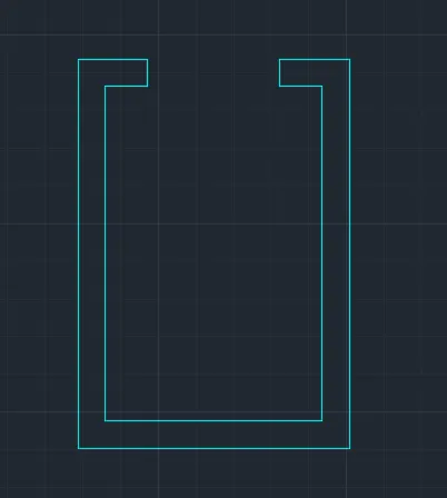
⦁ Draw the wall of the facade in plan with the required dimensions and exclude the window.
⦁ next we draw the window with the required dimensions.
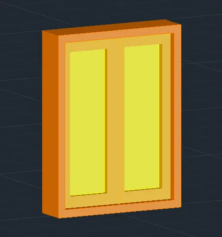
⦁ after we have to draw the windows and offset the window to provide a frame, panel and glass.
⦁ create a layer for the frame, panel and glass and give the different colour for them.
⦁ use the command extrude and extrude the window.
⦁ use the boundary command to pick the boundary.
⦁ extrude the wall using the command extrude to the required height.
⦁ create a rectangle to create the window opening in the wall.
⦁ extrude the window openign and paste to different elevations wherever the window required.
⦁ substract the wall using the command substract to attach the window.
⦁ attach the window using the copy option and paste it at the required postion.
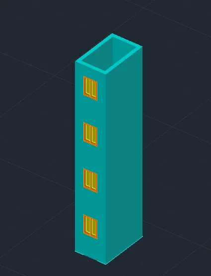
⦁ use the layer command to create the roof layer and the wall.
⦁ use the 3D orbit command to create a different view.
RESULT:
⦁ The given 3d isometric view of the building facade is drawn by using the autocad.
3. AIM:
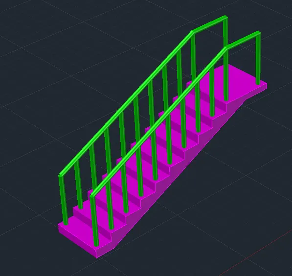
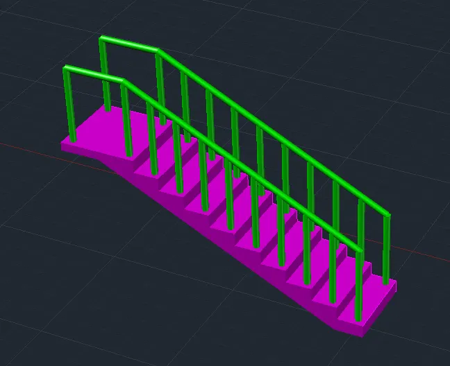
⦁ To create the isometric 3d view of the stair with railing as shown in the plan and elevation.
COMMANDS USED:
⦁ line
⦁ rectangle
⦁ UCS
⦁ region
⦁ extrude
⦁ substract
⦁ 3D Orbit
⦁ union
⦁ plan
⦁ erase.
PROCEDURE:
⦁ Set the units in engineering and in inches.
⦁ set the min and max. limits.
⦁ next we draw the stair using the line command with the proper dimension.
⦁ copy the lines to create the stair.
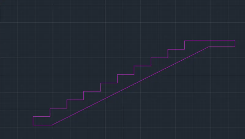
⦁ next we use the 3d rotate to rotate the figure.
⦁ we use the extrude command to extrude the rotated figure to form the stair in 3d view.
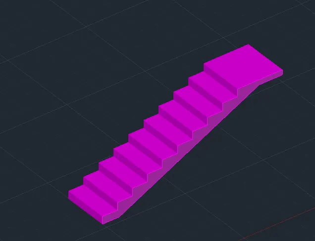
⦁ next we draw the railing using the circle command and sweep command.
⦁ next we use the 3d orbit command to create the different view of the stairs.
RESULT:
⦁ The given 3d isometric view of the stair is drawn by using the autocad.
4. AIM:
⦁ To create the 3d view of the wall with spread footing and need to create a rendered view of the model with materials.
COMMANDS USED:
⦁ line
⦁ rectangle
⦁ UCS
⦁ region
⦁ extrude
⦁ substract
⦁ 3D Orbit
⦁ union
⦁ plan
⦁ erase.
PROCEDURE:
⦁ Set the units in decimal and millimetres.
⦁ set the min and max. limits.
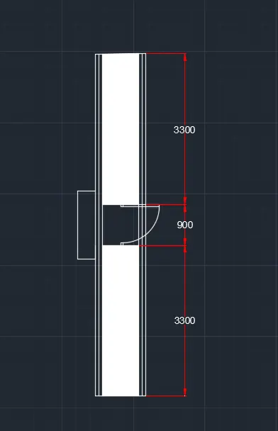
⦁ next we have to draw the plan of the wall with the spread footing with the given dimensions.
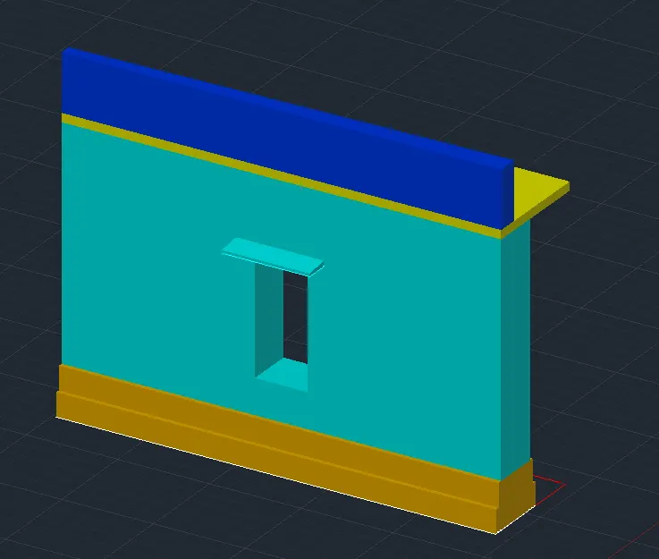
⦁ next we draw the 3d isometric view of the wall with spread footing using the extrude command.
⦁ next provide the layer of the wall with the spread footing with the different colours for the different parts.
⦁ use the material assign and assign the concrete and wall materials.
⦁ next we select the camera and put in the required postition and then press enter.
⦁ next click the camera then the small tab will appear at the top of left corner.
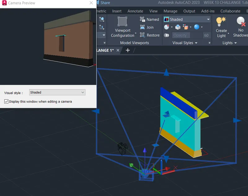
⦁ finally we select the render option and then slowly it changes to the rendering view.
RESULT:
⦁ The 3d view of the wall with spread footing and created a rendered view of the model with the material is drawn by using the autocad.