Creating 3D Isometric view of various structural elements in AutoCAD
1.
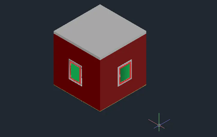
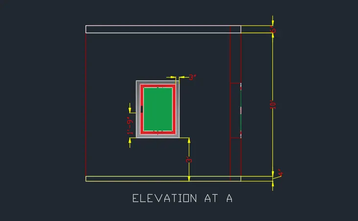
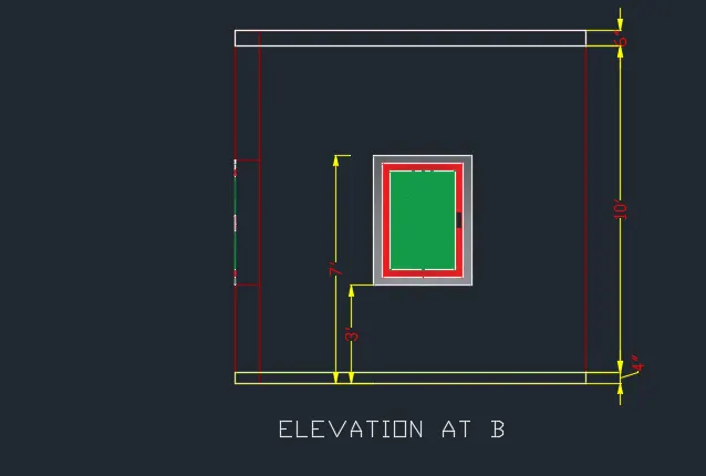
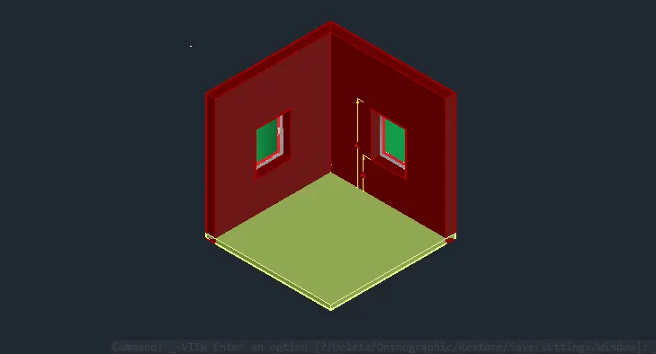
Aim :- To Create a 3D Isometric View of the building with plan and elevation given.
Â
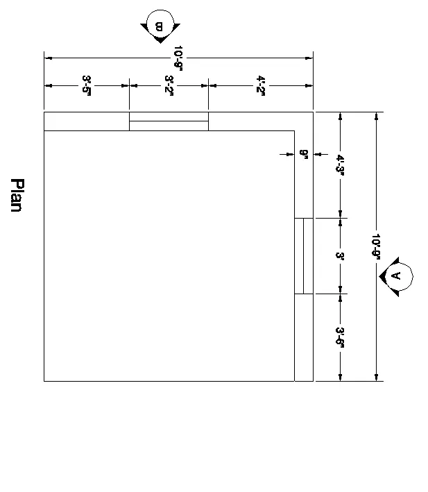
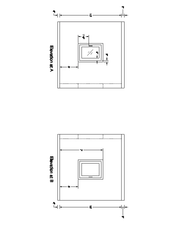
Â
Procedure :-
- Click on AutoCAD application and open this application
- Type QNEW in command bar and enter
- Select default setting as Imperial
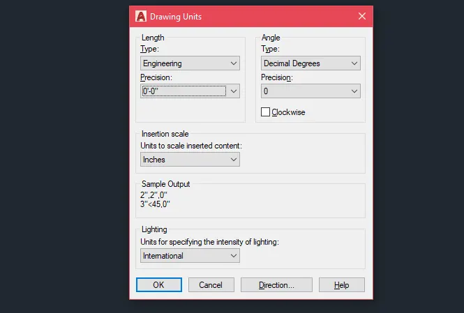
- In default setting click on use a wizard and in that advance setting and set unit as Engineering and precision as 0’0†and press Next
- Set Angle as Decimal Degree and precision as 0 and click next
- Set Angle Measure as EAST and press NEXT
- Set Angle Direction as Counter-Clockwise and press NEXT
- Set Area by providing Length as 50’ and Width as 50’
- Press finish
- Keep ortho, Object snap >ON
- Keep Snap and Grid > Off
- Un+enter
- Type > Engineering, Precision > 0’0â€
- Units to scale inserted content > Inches
- Enter
STEP.1 :-
- Take the rectangle command
- Specify first corner anywhere in the drawing
- Click > Dimension
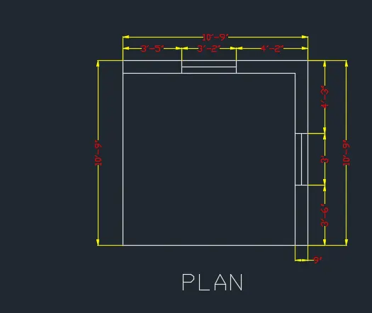
- Specify Length > 10’9â€
- Specify Width > 10’9â€
- Enter
- Take explode command
- Select object > Click on rectangle
- Take the offset command
- Specify offset distance > 9â€
- Enter
- Select the object > Select the object to show the wall thickness
- Provide the Windows by using line and offset command
- Click on ANNOTATION tab
- Click on Dimension
- Click > Manage dimension style
- New
- Style name > 3DSet the characteristics of dimensions as
- Select the colour for the dimension style and extension line
- Select arrowhead size as 4â€
- Select the text as colour
- Then select linear dimensions
- Provide the linear dimension
- The plan is ready
Â
Â
Â
- Select workspace switching > 3D Modelling
- Select Visual style control > 2D Wireframe
- Take 3D Orbit command
- Select view such as the UCS direction is as shown below
Â
 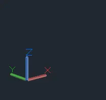
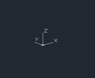
Â
Â
- Take boundary command
- Dialogue box will open
- Click on > Pick a point
- Click on the internal portion of wall
- Enter
- Take the extrude command
- Select object > Click on the walls
- Specify extrude height > 10’10â€
- Enter
- Change the visual style control > Shaded
- It will shows the following result
Â
 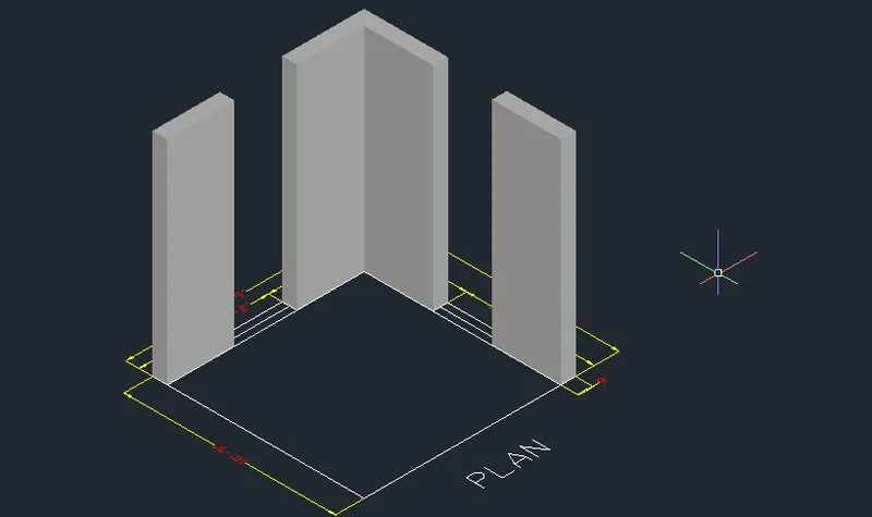
Â
Â
- Take the rectangle command
- Specify corner point > click on the any corner of the window
- Specify opposite corner > Click the opposite corner of the window
- Take the extrude command
- Select object > Select the rectangle
- Provide the extrude height > 3’
- Use the Extrude, Substract and union command to provide the window
- Similarly by using this process provide the another window
- Take the ucs command
- Select the wall having 3’ window
- Take a rectangle command
- Specify corner point anywhere in the drawing
- Click > Dimension
- Specify length > 3’
- Specify width > 4’
- Enter
- Take offset command
- Specify offset distance > 3’
- Select object > Click the rectangle
- Give offset inside the rectangle
- Again take offset command
- Offset the last object at a distance of 4’
- Use the suitable hatch command in the windows
 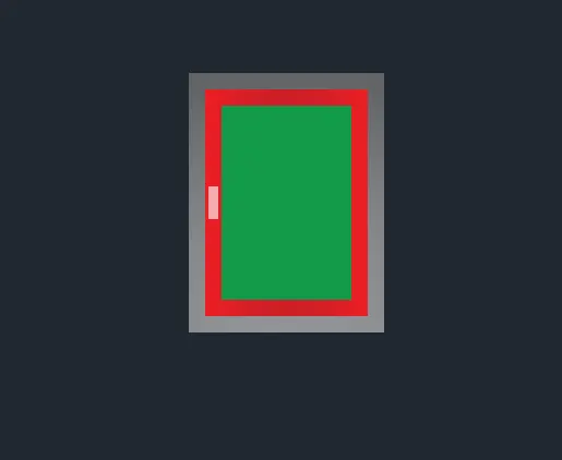
Â
- Similarly use the same procedure to create the window at other side of the wall
Â
- Use the move command to fix the window at proper position
- Use the UCS command and dimension command to show the dimensions
- Change visual style controls > Shaded
- The 3D drawing is ready
Â
Â
Result :-
Â
Â
 South West Isometric view:-
Â
 South East Isometric view:-
 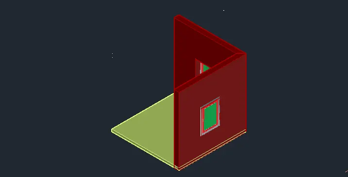
Â
North West Isometric view:-
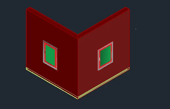
Â
Â
2.
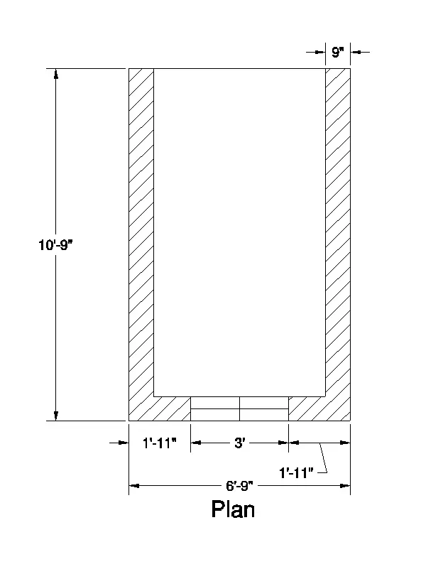
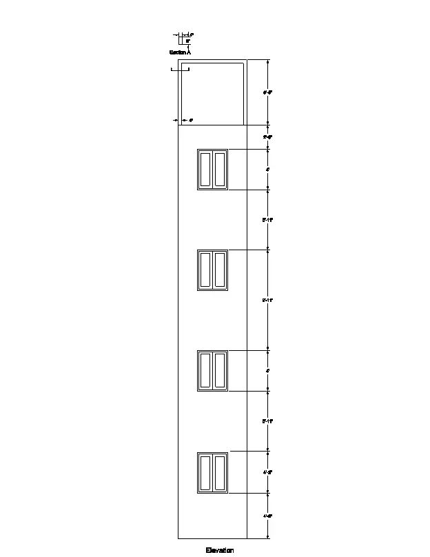
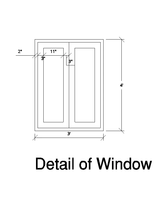
Aim :- To Create the 3D View of the Building Façade as given in the plan and elevation.
Â
Â
Â
Â
Procedure :-
- Click on AutoCAD application and open this application
- Type QNEW in command bar and enter
- Select default setting as Imperial
- In default setting click on use a wizard and in that advance setting and set unit as
- Engineering and precision as 0’0†and press Next
- Set Angle as Decimal Degree and precision as 0 and click next
- Set Angle Measure as EAST and press NEXT
- Set Angle Direction as Counter-Clockwise and press NEXT
- Set Area by providing Length as 50’ and Width as 50’
- Press finish
- Keep ortho, Object snap >ON
- Keep Snap and Grid > Off
- Un+enter
- Type > Engineering, Precision > 0’0â€
- Units to scale inserted content > Inches
- Enter
Â
Â
Â
- Take the rectangle command
- Specify first corner anywhere in the drawing
- Click > Dimension
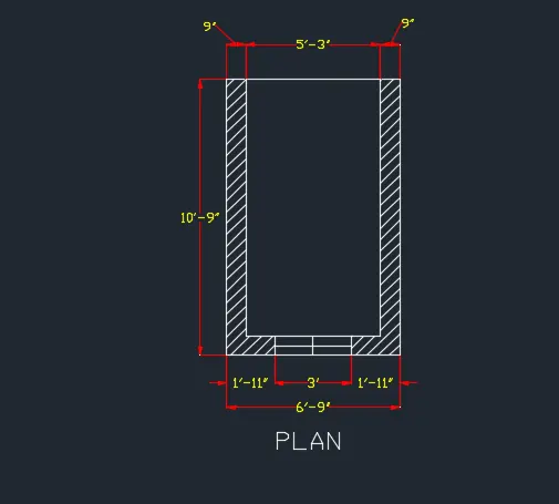
- Specify Length > 6’9â€
- Specify Width > 10’9â€
- Enter
- Take explode command
- Select object > Click on rectangle
- Take the offset command
- Specify offset distance > 9â€
- Enter
- Select the object > Select the object to show the wall thickness
- Provide the Windows by using line and offset command
- Click on ANNOTATION tab
- Click on Dimension
- Click > Manage dimension style
- New
- Style name > 3D
- Set the characteristics of dimensions as
- Select the yellow colour for the dimension style and extension line
- Select arrowhead size as 4â€
- Select the text as Cyan colour
- Then select linear dimensions
- Provide the linear dimension
- The plan is ready
Â
Â
- Select workspace switching > 3D Modelling
- Select Visual style control > 2D Wireframe
- Take 3D Orbit command
- Select view such as the UCS direction is as shown below
Â
Â
Â
- Take boundary command
- Take boundary command
- Dialogue box will open
- Click on > Pick a point
- Click on the internal portion of wall
- Enter
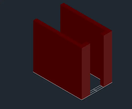
- Take the extrude command
- Select object > Click on the walls
- Specify extrude height > 9’11â€
- Enter
- Change the visual style control > Shaded
- It will shows the following result
Â
Â
Â
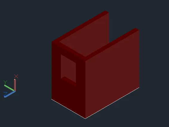
- Take the rectangle command
- Specify corner point > click on the any corner of the window
- Specify opposite corner > Click the opposite corner of the window
- Take the extrude command
- Select object > Select the rectangle
- Provide the extrude height > 3’
- Use the Extrude, Substract and union command to provide the window
- Similarly by using this process provide the another window
Â
Â
Â
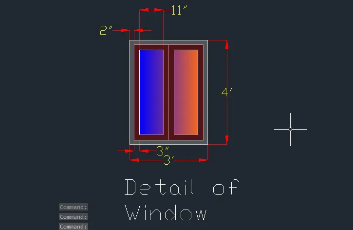
- Take the ucs command
- Select the wall havng window
- Take a rectangle command
- Specify corner point anywhere in the drawing
- Click > Dimension
- Specify length > 3’
- Specify width > 4’
- Enter
- Take offset command
- Specify offset distance > 2’
- Select object > Click the rectangle
- Explode the rectangle
- Divide the inner rectangle in two parts by using line command
- Give offset inside the rectangle
- Again take offset command
- Provide the offset of 3†to dividation part to show the glass
- Use the suitable hatch command in the windows
Â
Â
Â
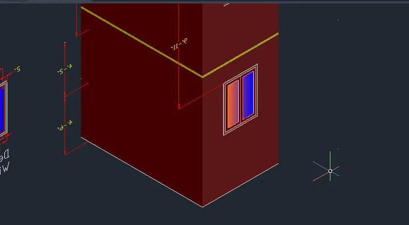
- Use the move command to fix the window at proper position
Â
Â
Â
Â
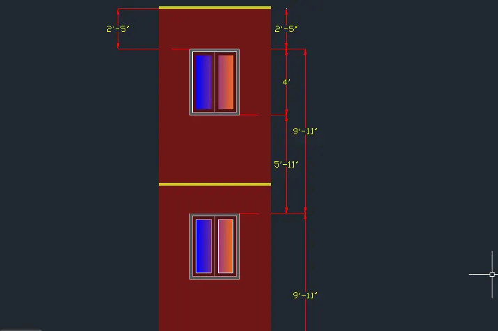
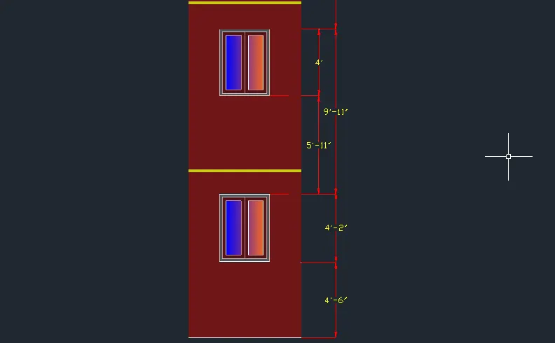
- Respectively make the all 4 floor as per the required dimenssion.
Â
Â
Â
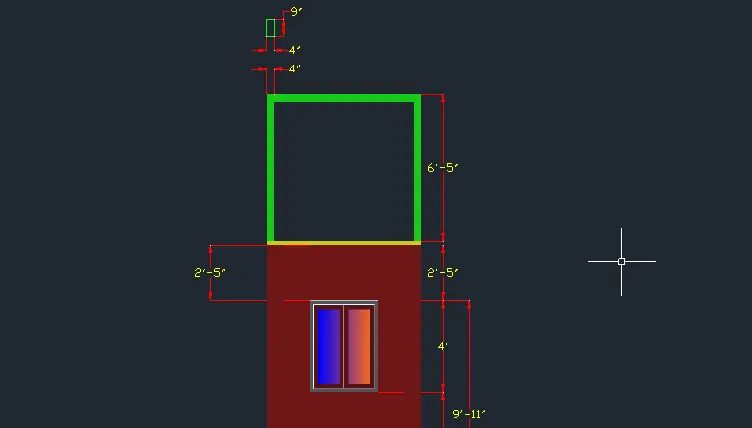
- Take line command and extrude command to show the upper portion of building
Â
Â
Â
Â
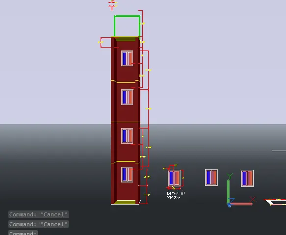
- Take the ucs command
- Select the front face of the building to provide the dimensions
- By using continuous dimension command provide all the dimensions
Â
Â
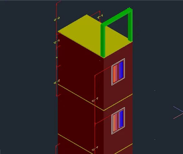
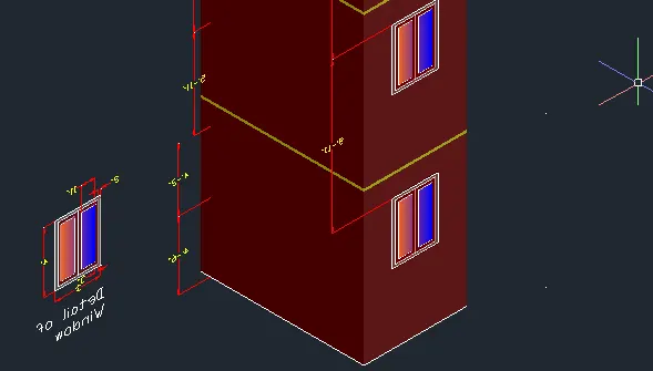
Result :-
Â
Â
Â
Â
3.
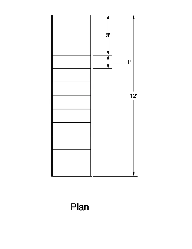
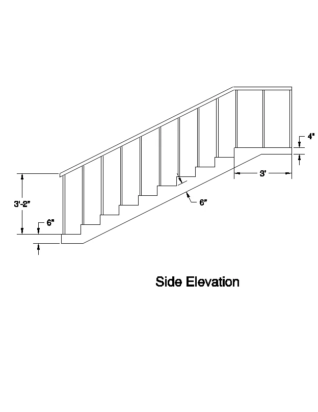
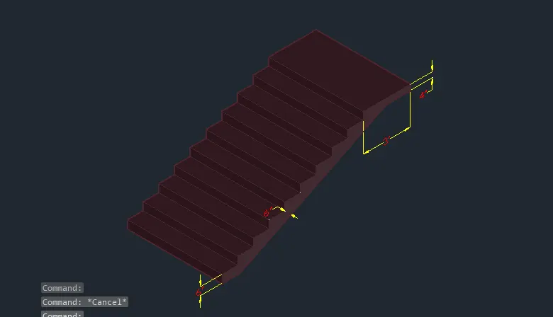
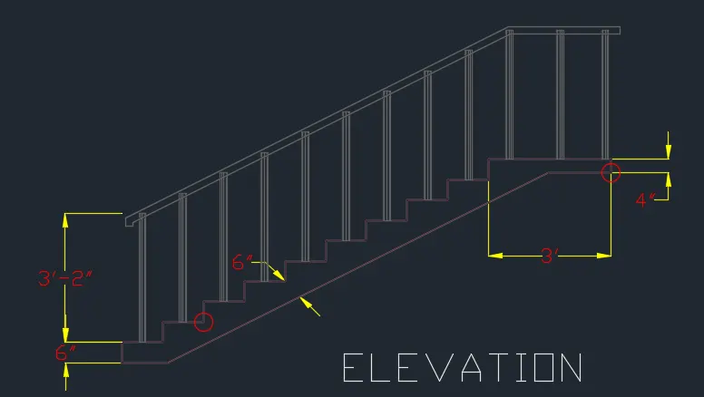
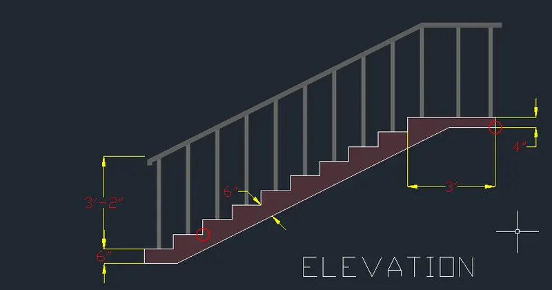
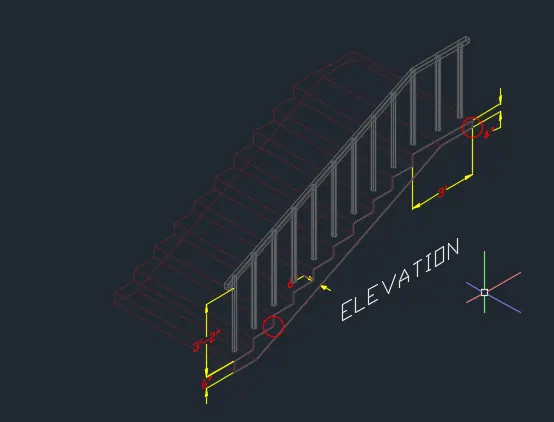
Aim :-Â To Create the ismoteric 3d view of a stair with railing as shown in the plan and elevation
Â
Â
Â
Procedure :-
- Click on AutoCAD application and open this application
- Type QNEW in command bar and enter
- Select default setting as Imperial
- In default setting click on use a wizard and in that advance setting and set unit as
- Engineering and precision as 0’0†and press Next
- Set Angle as Decimal Degree and precision as 0 and click next
- Set Angle Measure as EAST and press NEXT
- Set Angle Direction as Counter-Clockwise and press NEXT
- Set Area by providing Length as 50’ and Width as 50’
- Press finish
- Keep ortho, Object snap >ON
- Keep Snap and Grid > Off
- Un+enter
- Type > Engineering, Precision > 0’0â€
- Units to scale inserted content > Inches
- Enter
Â
Â
Â
- Select workspace switching > 3D Modelling
- Select Visual style control > 2D Wireframe
- Take 3D Orbit command
- Select view such as the UCS direction is as shown below
Â
Â
Â
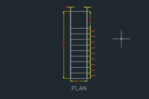
- Take a Rectangle command
- Specify first point > Anywhere in the drawing
- Then select D.
- Set length as 3'.
- width as 12'.
- Make the rectangle Explode then thake offset of 1" from the left and right side.
- Then make 9 offset of 1' each from the bottom
- Click on Dimension
- Click > Manage dimension style
- New
- Style name > 3D
- Set the characteristics of dimensions as
- Select the yellow colour for the dimension style and extension line
- Select arrowhead size as 4â€
- Select the text as Cyan colour
- Then select linear dimensions
- Provide the linear dimension
- The plan is ready
Â
Â
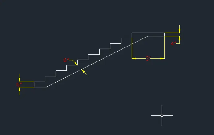
- Take a line command
- Specify first point > Anywhere in the drawing
- Specify next point as > @0,0,6†> Enter
- Specify next point as > @1’,0,0 > Enter
- Specify next point as > @0,0,6†> Enter
- Specify next point as > @1’,0,0 > Enter
- Specify next point as > @0,0,6†> Enter
- Specify next point as > @1’,0,0 > Enter
- Specify next point as > @0,0,6†> Enter
- Specify next point as > @1’,0,0 > Enter
- Specify next point as > @0,0,6†> Enter
- Specify next point as > @1’,0,0 > Enter
- Specify next point as > @0,0,6†> Enter
- Specify next point as > @1’,0,0 > Enter
- Specify next point as > @0,0,6†> Enter
- Specify next point as > @1’,0,0 > Enter
- Specify next point as > @0,0,6†> Enter
- Specify next point as > @1’,0,0 > Enter
- Specify next point as > @0,0,6†> Enter
- Specify next point as > @1’,0,0 > Enter
- Specify next point as > @0,0,6†> Enter
- Specify next point as > @3’,0,0 > Enter
- Specify next point as > @0,0,-4†> Enter
- Enter
- Provide the weist slab of 6†by using line and offset command
Â
- Take the boundry command
- Pick internal point
- Select the nternal portion of staircase
- Enter
- Visual style control > Shaded
- Take extrude command
- Extrude the stairs at 3’
Â
Â
Â
- Take a circle command
- Specify centre > At railing position
- Click > Diameter
- Specify diameter > 1â€
- Enter
- Extrude that circle at a height > 3’2â€
- Copy that cylinder and place it in a proper position
- Use the line and sweep command to draw the horizontal handgrill
- Draw 2",2" squre to sweep the handgrill.
- Click on ANNOTATION tab
- Click on Dimension
- Click > Manage dimension style
- New
- Style name > 3D
- Set the characteristics of dimensions as
- Select the yellow colour for the dimension style and extension line
- Select arrowhead size as 4â€
- Select the text as Green colour
- Then select linear dimensions
- Provide the linear dimension
- Use the ucs command to show the dimensions
- The 3D staircase is ready
Â
Â
Â
Â
Result :-
Â
View 1
Â
Â
View 2
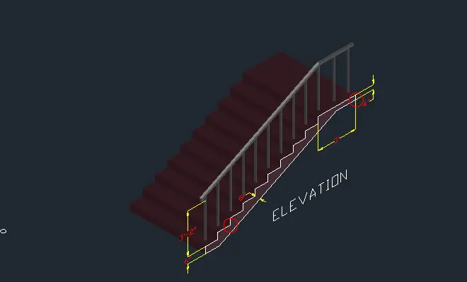
View 3
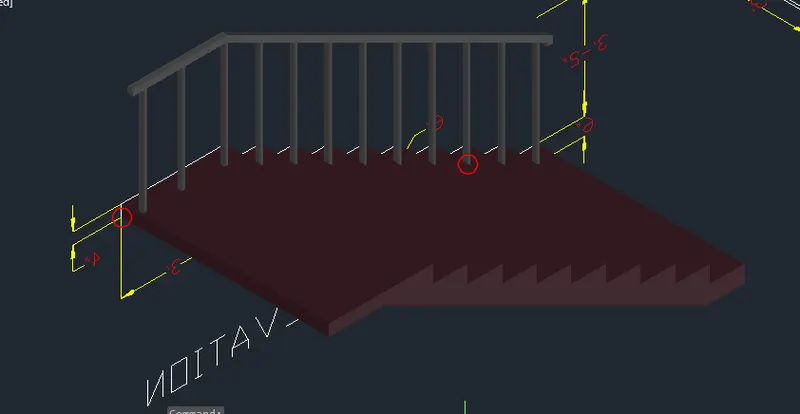
Â
4.
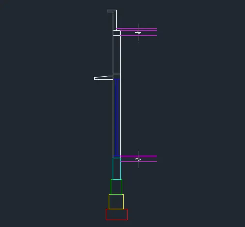
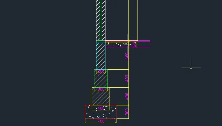
Aim :-Â To Create the 3D view of a Wall with spread footing bu using the plan and section shown below
Â
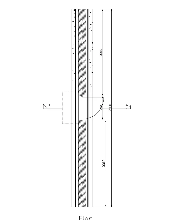
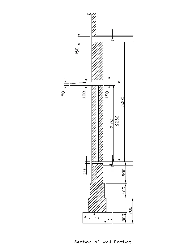
Â
Â
Procedure :-
- Click on AutoCAD application and open this application
- Type QNEW in command bar and enter
- Select default setting as Imperial
- In default setting click on use a wizard and in that advance setting and set unit as Decimal and precision as 0 and press Next
- Set Angle as Decimal Degree and precision as 0 and click next
- Set Angle Measure as EAST and press NEXT
- Set Angle Direction as Counter-Clockwise and press NEXT
- Set Area by providing Length as 10 m and Width as 10m
- Press finish
- Keep ortho, Object snap >ON
- Keep Snap and Grid > Off
- Un+enter
- Type > Decimal, Precision > 0’0â€
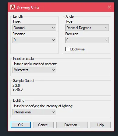
- Units to scale inserted content > Milimeter
- Enter
Â
Â
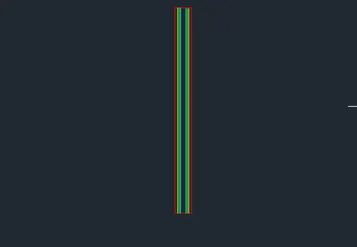
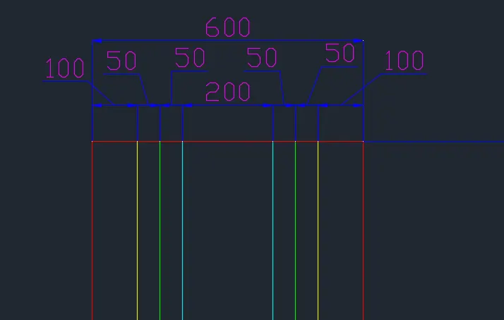
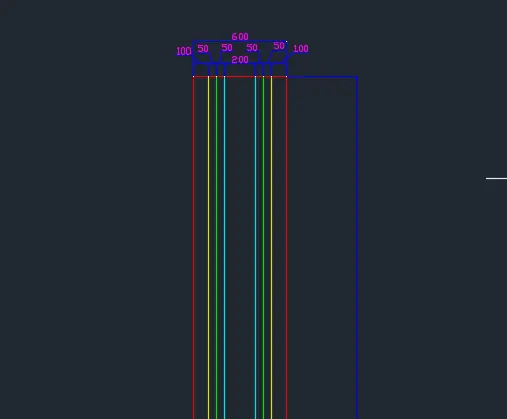
- Draw a rectangle of dimensions 600X7500 and explode it.
- Offset the rectangle to inside to a distance of 100mm both left and right side.
- Offset the offset rectangle inside to distance of 50mm twice.
- Explode all the offset rectangle
- Delete the top and bottom edges of the exploded rectangles
- Extend all the rectangle to top and bottom edges of outer rectangle.
- At the end select the individual lines and change their layers respectively
Â
- Creating Door Block
- Draw a rectabgle of dimenson 50X100mm
- Draw an arc line of the door swing
- Convert the door into block
- Edit the block and add flip parameters
- Create the door opening of 900mm at the middle
- Add the door block by rotating the door
- Add the door shade using respective layer
Â
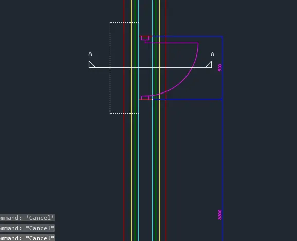
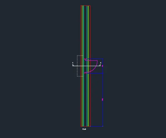
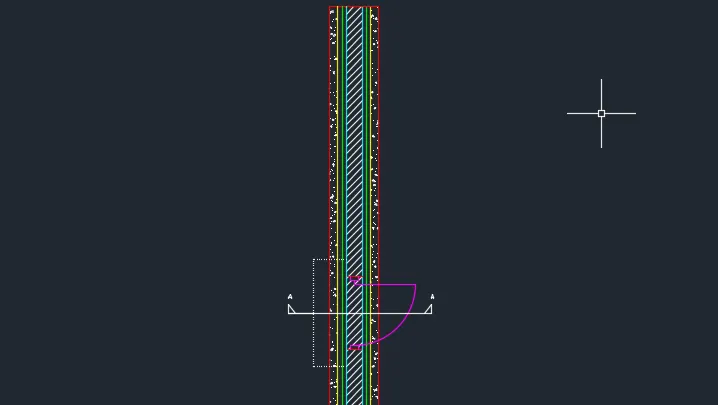
- Hatch the object in a proper way and complect the PLAN view.
  
Â
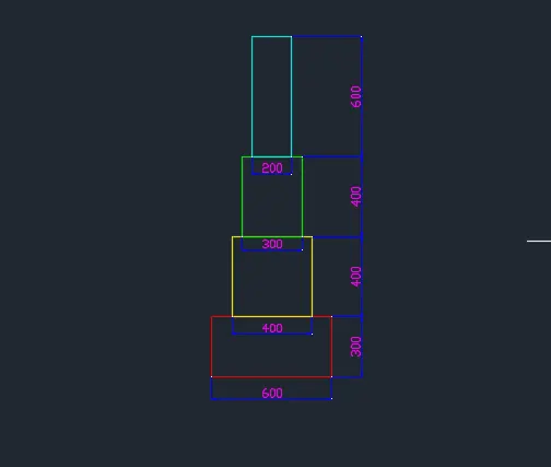
- Take the rectangle command
- Specify first corner anywhere in the drawing
- Click > Dimension
- Specify Length > 700
- Specify Width > 300
- Enter
- Take explode command
- Take the rectangle command
- Specify first corner 150 unit dist. from the previous rectangle top person.
- Click > Dimension
- Specify Length > 400
- Specify Width > 400
- Enter
- Take explode command
- Take the rectangle command
- Specify first corner 50 unit dist. from the previous rectangle top person.
- Click > Dimension
- Specify Length > 300
- Specify Width > 400
- Enter
- Take explode command
- Take the rectangle command
- Specify first corner 50 unit dist. from the previous rectangle top person.
- Click > Dimension
- Specify Length > 200
- Specify Width > 600
- Enter
- Take explode command
Â
Â
Â
Â
- Take the rectangle command
- Specify first corner from the previous rectangle top left person.
- Click > Dimension
- Specify Length > 200
- Specify Width > 3350
- Enter
- Take explode command
- Take offset command.
- From the top person of the previously created rectangle take offset dist. of 50,2150,2300 respectively.
Â
Â
- Click on ANNOTATION tab
- Click on Dimension
- Click > Manage dimension style
- New
- Style name > 3D
- Set the characteristics of dimensions as
- Select the yellow colour for the dimension style and extension line
- Select arrowhead size as 200
- Select the text as Green colour
- Then select linear dimensions
- Provide the linear dimension
Â
 
Â
- Select workspace switching > 3D Modelling
- Select Visual style control > 2D Wireframe
- Take 3D Orbit command
- Select view such as the UCS direction is as shown below
Â
Â
- Take boundary command
- Dialogue box will open
- Click on > Pick a point
- Click on the internal portion of wall
- Enter
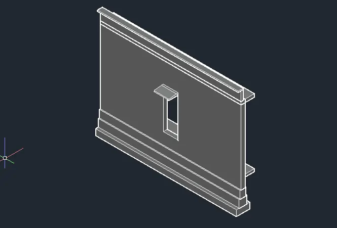
- Take 3d rotate command and rotate it to make it in XZ Plane
- Take the extrude command
- Select object > Click on the boundry
- Specify extrude height > 7500
- Enter
- Change the visual style control > Shaded
- It will shows the following result
Â
Â
- Take UCS Command
- Click in front of the wall to work on that wall
- Use rectangle command, Extrude command and subtract command to leave the space fo
- the door
- Take a material browser command
- Select > Wall painting
- Select the portion
- And Assigh the material
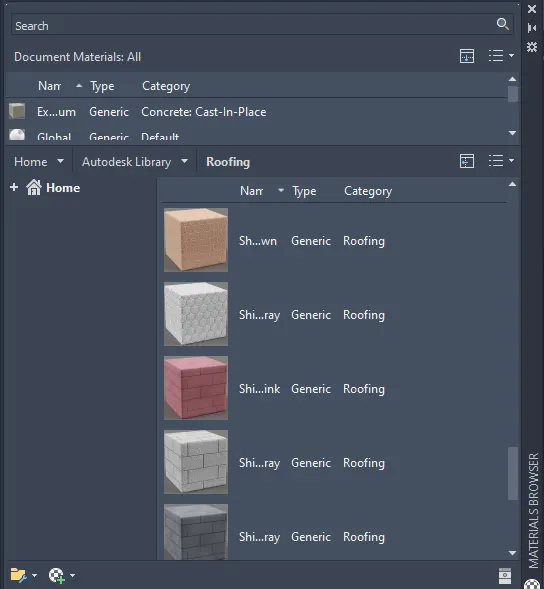
- By using similar process, assign the materials for all the components
- The 3D Drawing is ready
 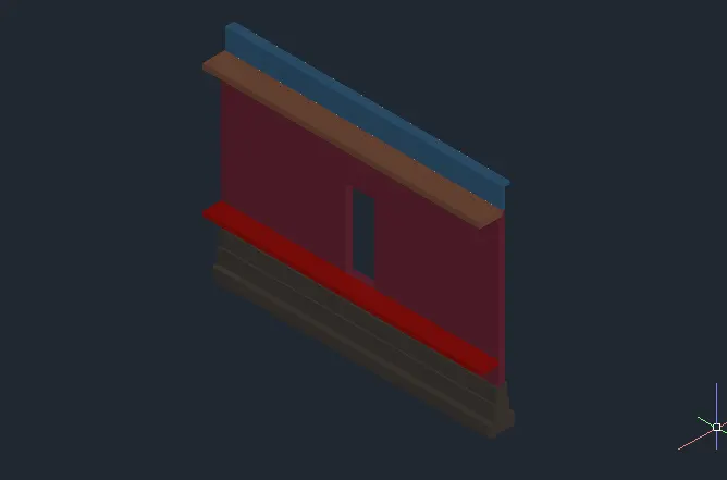
Result :-
- View 1:-
Â
- View 2:-
 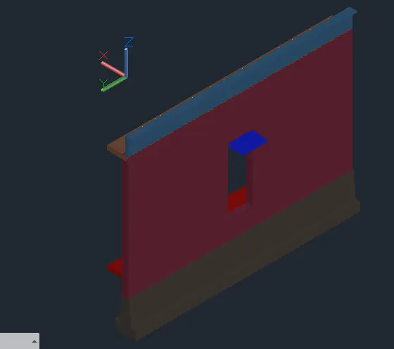
- View 3:-
 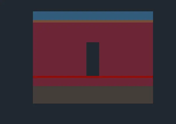
Â
 RESULT:-
1.Â
Â
Â
Â
Â
Â
Â
Â
 RESULT:-
2.Â
Result :-
Â
Â
Â
 Â
 RESULT:-
3.Â
Â
Â
View 1
Â
Â
Â
 RESULT:-
4.Â
 Â
Â
Â
Â
Â
Â
Â
Â
Â
Â
Â