Creating 3D Isometric view of various structural elements in AutoCAD
1. Create a 3D Isometric View of the building with plan and elevation given.
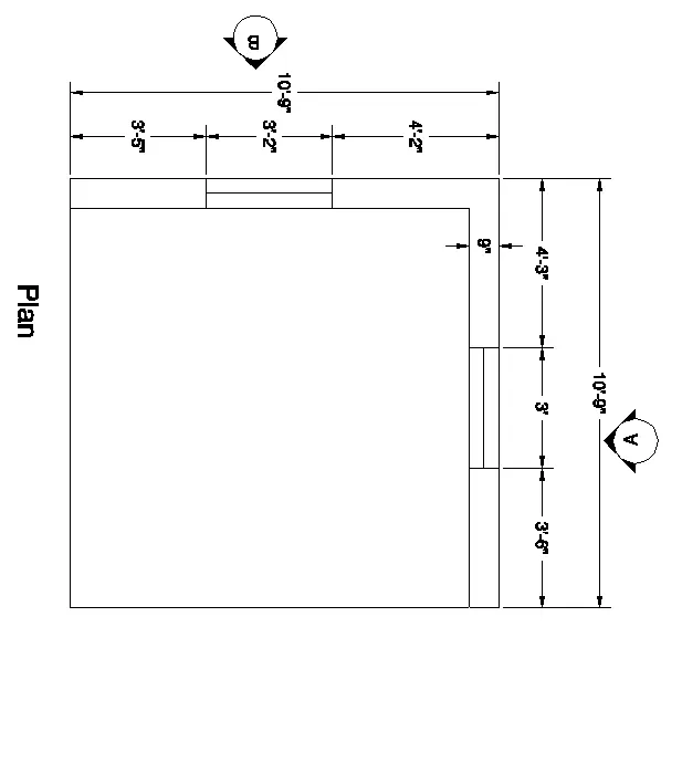
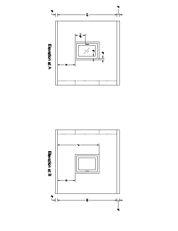
Procedure :
Plan :
- Creat a autocad file and give the units as the feet and inches
- change snap and grid scpacing to 1"
- Change the draft setting as to the 3d modelling
- Take the box command from Ribbontool and given the length and width of 10'9"x 10'9" .
- Creat the layer properties using the layers from the layer properties .
- Creat the rectangle dimension of 10'9"x 10'9" and give the offset of 9" wall thickness.
- Delete the left bottom lines and extend them to the edges as shown in the fig
- And Given the window dimensions 3'-2" at top and 3' on right side as shown in figure .
- And Give the Boundaries foe the walls using the boundary command .
- Extrude the wall in to the height of 10'10". and make into group then together .
- Draw rectangles at the both side and give the boundary and using the extrude command give the height of 3'-4.
Elevation at AA:
- Draw the rectangle of dimension 3'and 4'
- And give the rectangle to inside of 3"and 4" . and frame for the window and subtract the inner for thw window .
- And the Draw the other rectangle inside of it and subtract the above to from the glaas of the inner window.
- And Give the all layer apply for the window and give the extruded for the frame of the window as shown the figure.
Elevation at B:
- Draw the rectangle of dimension 3'and 4'
- And give the rectangle to inside of 3"and 4" . and frame for the window and subtract the inner for thw window .
- And the Draw the other rectangle inside of it and subtract the above to from the glaas of the inner window.
- And Give the all layer apply for the window and give the extruded for the frame of the window as shown the figure.
- And give the Visuvilse tab and view on the view
- And Creat and view for the paln and two elevation windows when we required show as the current view of it.
- And Give the dimension using the dimlinear and give the apply the respective layer using the layer command .
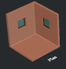
2. Create the 3D View of the Building Façade as given in the plan and elevation. Also, see the detail of the window.
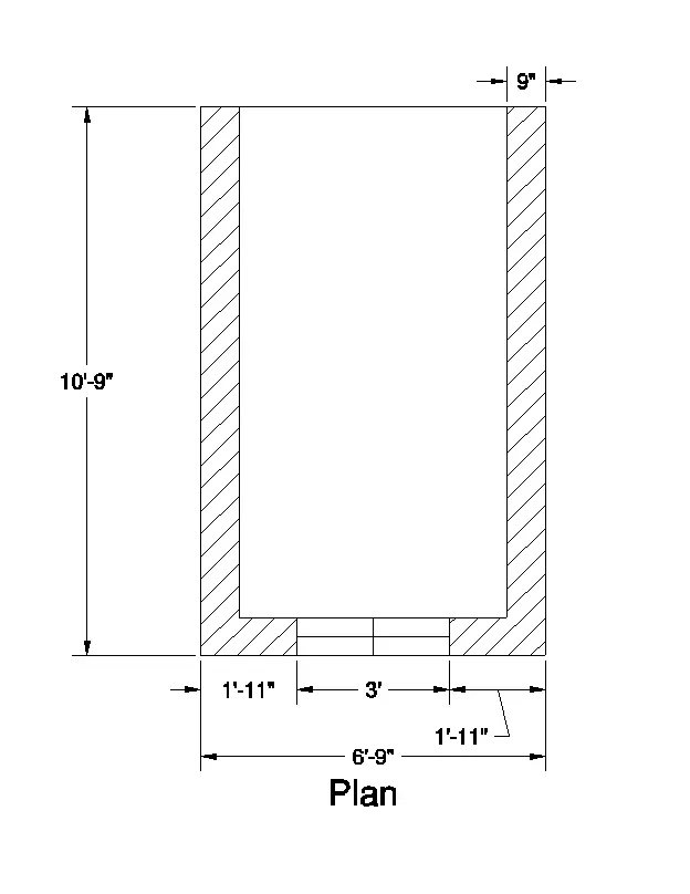
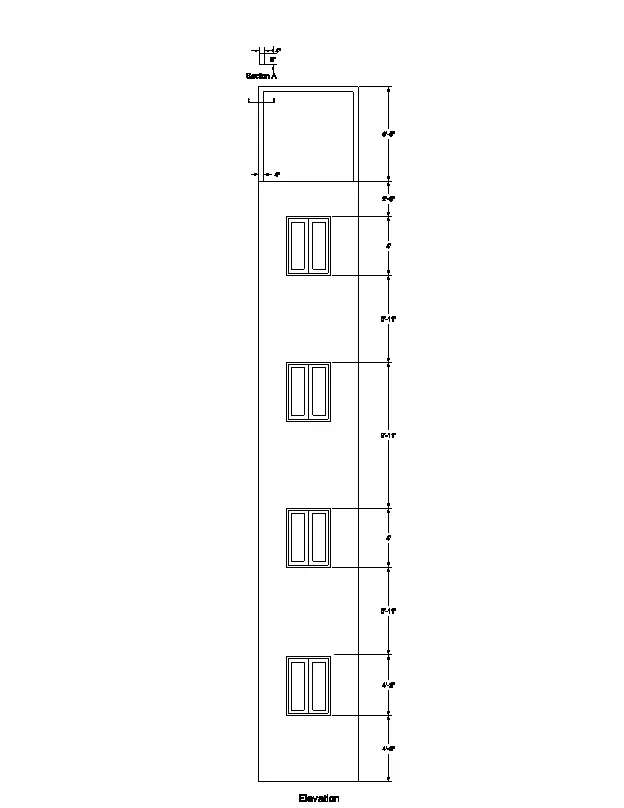
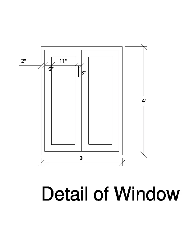
Procedure :
plan :
- Creat a autocad and set the autocad file and set the units and limits settings .
- Draw the rectangle of dimension of 6'-9"x 10'-9" .
- And Give th inner wall thickness of 9"
- And Give the window size of 3' at 6'-9" Next select the boundary command and give the doundary for it
- And using the region command and select the object and enter .
- And give the extrude command of height of wall 10'10". and delete the windows lines .
- creat the window and give the boundary for the window and recreat the region command and extrude uo to the height of 4'6" and at the top recreat the region and extrude the below up to 1'-3" as show in the figure .
Elevation & Window details :
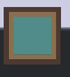
- Draw the rectangle for window of sizes of 3'x4'
- And give the offset of 2" and again give the 3"
- and draw the mid line for the rectangle and give the offset of 3" and trim the remaining lines in the window frame .
- And give the inner glass width of the 11" in the frame
- And Creat the boundary for the window framing using the pick the point.
- Using the subtract command subtract the bigger region from the smaller region .
- And creat the layers for the window frames and glass also and apply the later for the window .
- And give the extruded command for the window framing projection as show in fig.
- Place the window framing in the plan and creat a group for it.
- And Copy the 3time at the height of 4' as show in the figure .
- Creat the rectangle above the height of 6'-5" , and give the 4" and region for it and extrude for the 9"
- Creat the layer and apply the property layer for it.
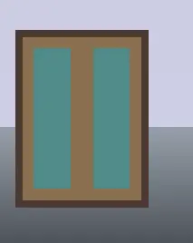
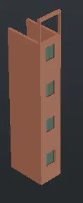
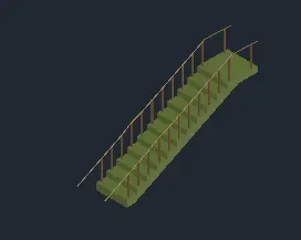
3. Create the ismoteric 3d view of a stair with railing as shown in the plan and elevation. Assume the size of the balustrades and the hand rails.
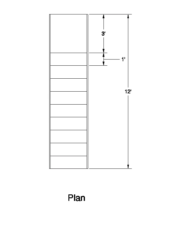
Plan :
- Creat the autocad file and give the setting for the units and limits .
- Draw the Staircase plan using the using the line command
- Given the line length of 12' and give the width of 3' .
- And Give the offset of 12" for the steps and give the midlanding width of 3'
- and give the 1" for the sides for the railing .
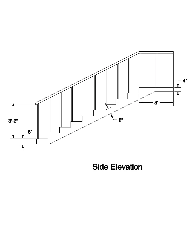
Side elevation :
- Using the line command of draw the section for the staircase
- Giving the riser 6" and thread of 12" and draw the 12 steps .
- And Give the midlanding of 3' and waistslab of thickness of 4" .
- Using the boundary command creat the boundary for the section .
- And Give the region using the region command for the staircase section
- Using the extrude of width of 3'
- Draw the railing using the circle command and use the sweep command . give the height of the railing of 3-2".
- Using the mirror command give the railing on the other side .
- Next we draw the railing using the circle command and sweep command.
4. Create the 3D view of a Wall with spread footing . Create the Door opening only. Assume the size of the parpaet and the coping. See the plans and elevation for the details. Also, create a rendered view of the model with materials as of your choice.
Procedure :
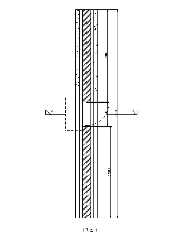
Plan :
- Creat the autocad file with set the units and limits .
- Draw a rectangle of dimension 670x7500 , offset the rectangle of 120mm
- Again offset of 50mm explode the offset rectangle .
- And give the layer properties for the lines it self .
- Create a door using the rectangle of dimension 50x100mm and other line length of 850mm
- draw the arc line for the door swing to convert the door and edit for the swing for the door And give the filp parameter.
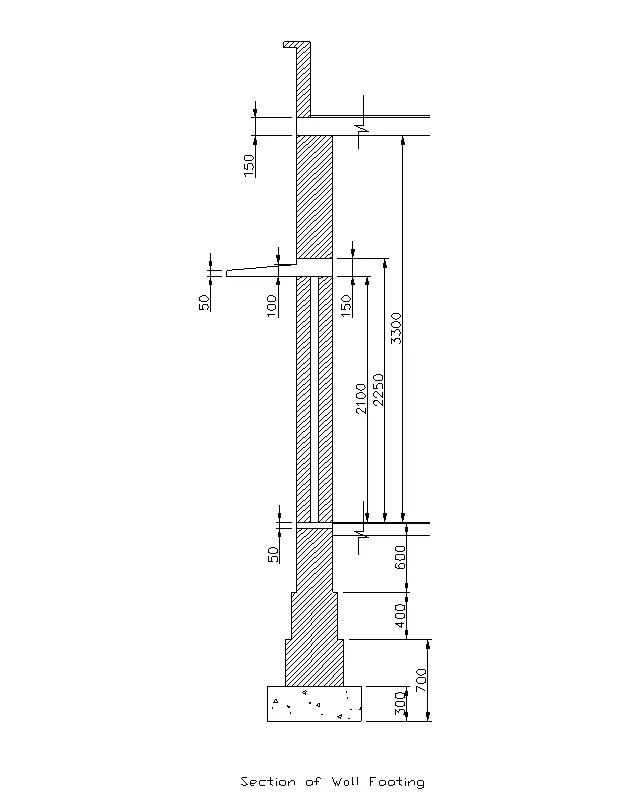
Section of wall footing :
- Creat the line of length and bottom of width of 25mm
- and offset for the other distance of 100mm, And give the rectangle of dimension of 230x3300 from the top left
- And Created a roof of thickness 150mm as show in fig
- and give the parpet wall height of 600mm as shown in fig.
- And Draw the rectangle of dimension of 230x600,330x400,430x400,670x300 as shown in figure.
- And Door length of 230mm at the ground level , 50mm line distance and offset of 2100 to the above .
- And using the boundaries for the boundarie command and using the extrude the distance of 7500mm
- Door opening is added by drawing a rectangle at the door location from the plan view .
- Extruded the door region is subtracted from the wall using the subtract command
- To created the door open for it and give the layer properties .
- Add the material to the section of the wall footing from the material objects.
- Box mapping is done adjust the material.
- Torch light is placed infront of the door at certail distance with fall off angle as 50 and hotspot angle as 80 as shown in figure and also distance.
- And Creating the views and setting the cam and intensity 1500 and set target to set th wall sections .
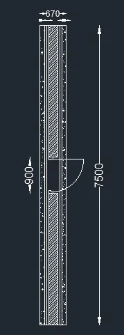
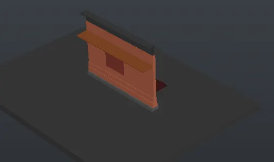
Result :