Creating 3D Isometric view of various structural elements in AutoCAD
AIM : To create 3D isometric view of various structural elements in AutoCAD
Introduction : Various isometric views of structural elements are created using following tools
- SOLID EDIT
- REGION
- BOUNDARY
- EXTRUDE
- SWEEP
- 3DORBIT
- PRESSPULL
- UNION
- SLICE
- ROTATE 3D
- RENDERING
- MATERIAL BROWSER
- CAMERA
- LIGHT
PROCEDURE :
- Open autocad application
- Type Qnew and open new drawing
- Set units according to drawing
- Switch ON 3D modeling in work space switching
- Switch on 2D object snap and 3D object snap modes
- Ortho mode is ON
PROBLEM 1
AIM : To create a 3D isometric view of the building using AutoCad
PROCEDURE :
- Set units to engineering
- Set units of dimensions to engineering
- Create layers
- Floor
- Wall
- Window Frame
- Window glass
- Window handle
- Window sash
- Roof
- Draw a rectangle of size 10'9" x 10'9"
- Take offset of distance 9" and draw lines at top and right side of rectangle
- Create window of windth 3'2" and 3' at a distance 3'5" and 3'6" as shown below
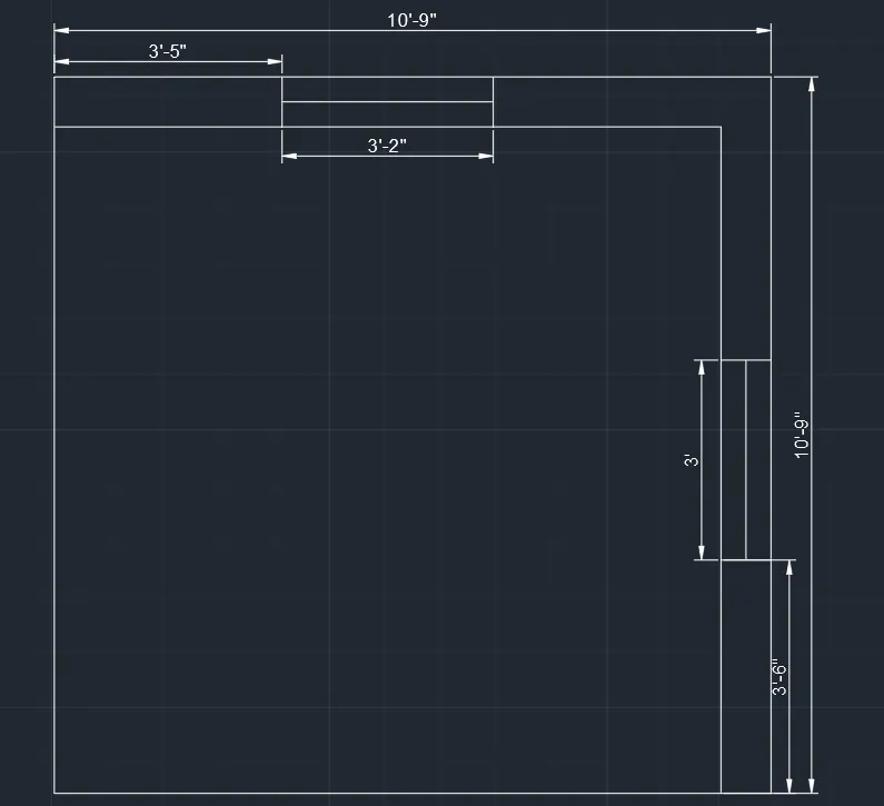
- Create boundary regions at walls and windows separately and extrude the those elements upto a height of 3' distance
- Create a rectangle on the window area
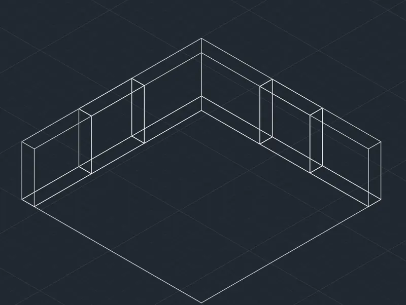
- To draw a window
- Create a window (in 2D) separately by drawing a rectangle of size 3'2" x 4' and 3' x 4'
- In each rectangle create two more rectangles by taking offset at a distance 3" and 4"
- Draw another rectangle of size 1" x 7" in each rectangle at a distance 1'9" as shown below
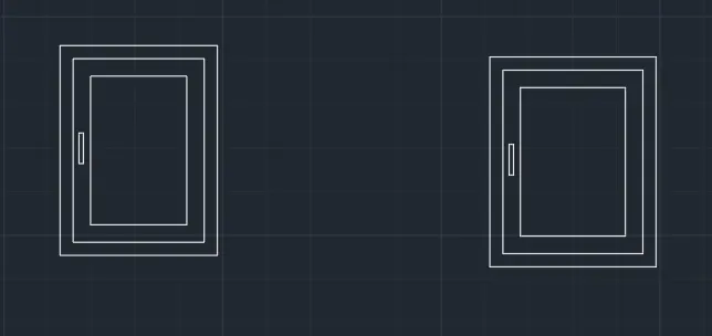
- Create boundaries of each rectangle and assign it to layers
- Window frame
- Window sash
- Window handle
- Window glass
- Extrude each element as given below
- Window frame -8"
- Window sash - 4"
- Window handle - 4"
- Move window sash, window glass, window handle towards back at a distance 2"
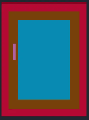
- Now turn to 3D and rotate rectangles using 3D rotate
- Place the windows at windows areas
- Using extrude command raise the walls at a height 7'
- Assign the walls to wall layer
- Now create a floor at the bottom of thickness 4"
- Create a roof at the top of thickness 6"
- Now open material browser in visualize tab
- Assign materials to following elements
- Floor
- Walls
- Roof
- Window
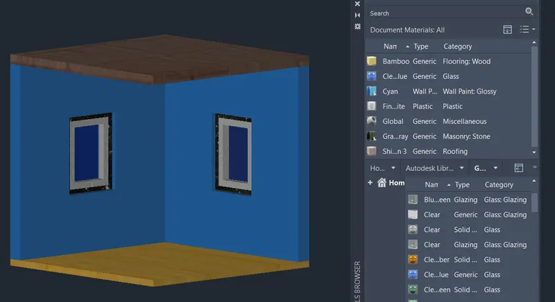
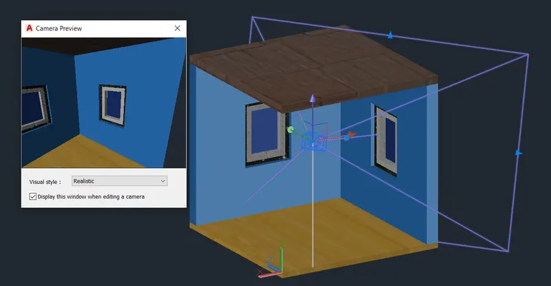
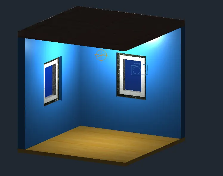
- Draw a cyclinder and place a camera
- Draw a cyclinder and place a light
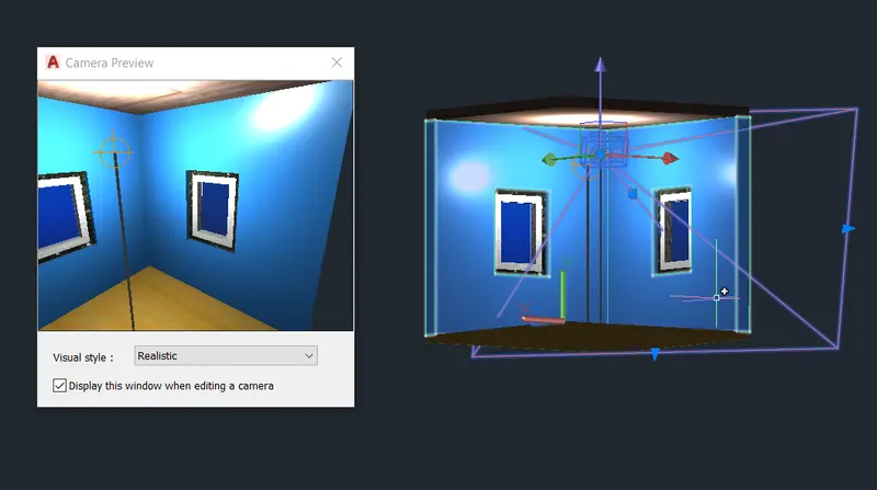
RESULTS :
3D view of a room is created
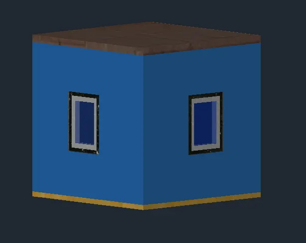
3D view of a room with light and camera
PROBLEM 2
AIM : To draw a 3D view of the building facade using AutoCad
PROCEDURE :
- Set units to engineering
- Set units of dimensions to engineering
- Create layers
- Wall
- Window Frame
- Window glass
- Window sash
- Projection
- (2D) Draw a rectangle of size 6'9" x 10'9"
- Take offset distance of 9" and draw horizontal and vertical line
- Draw a window of width 3' at a distance 1'11"
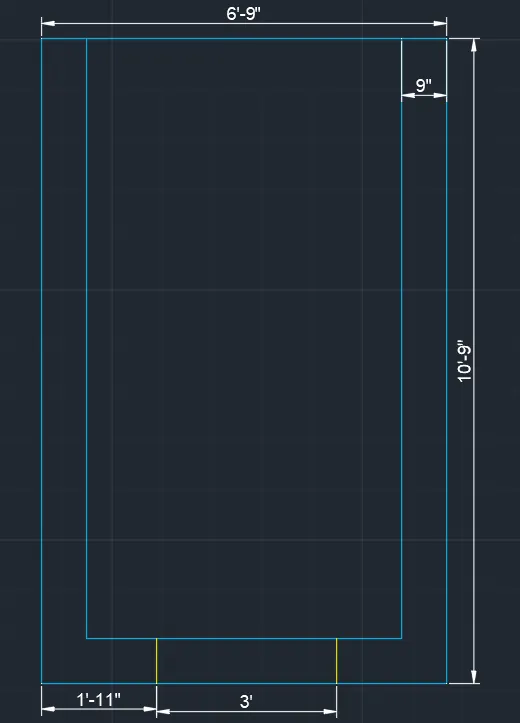
- Now turn to 3D view
- Create boundary region at window and wall area
- Using extrude raise the walls and also at window area at a height 4'6"
- To draw a window
- Draw a rectangle of size 3' x 4' separately
- Inside previous rectangle take offset distance of 2" and draw another rectangle
- Divide the previous rectangle into half
- Draw rectangles in each at a offset distance of 3"
- Create boundaries of each rectangle and assign it to layers
- Window frame
- Window sash
- Window glass
- Extrude each element as given below
- Window frame -9"
- Window sash - 4"
- Move window sash, window glass towards back at a distance 2"
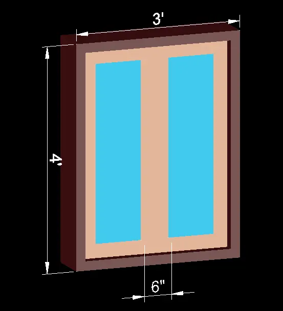
- Place this window on the wall created
- Draw the walls at a height upto 40'10" using extrude tool and in between place windows as shown below
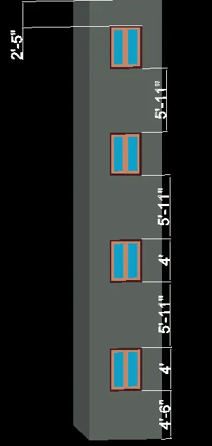
- Now draw projection at the top at a height 6'5", width 4" and length 9"
- Create a ground (20' x 20' x 1 ) under the building facade
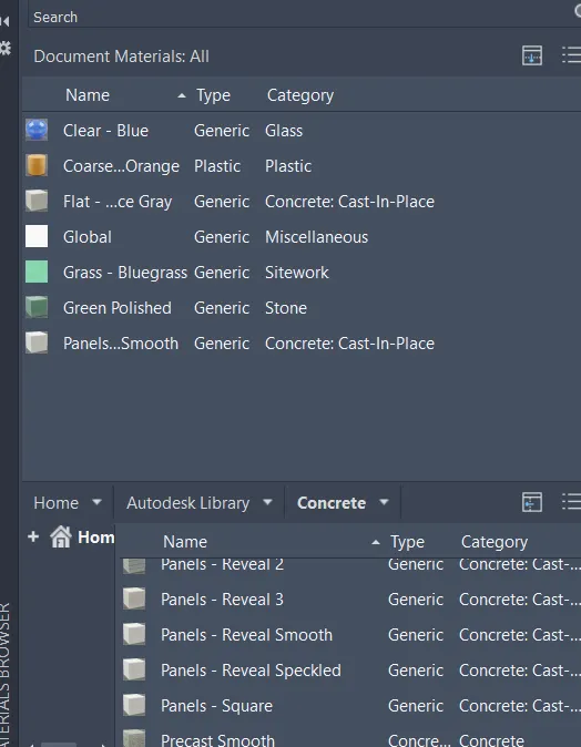
- Now open material browser in visualize tab
- Assign materials to following elements
- Walls
- Projection
- Window
- Ground
- Now go to render environment and exposure in render tab
- Switch on the environment and select image based lighting : Sharp highlights
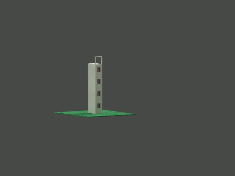
- Now click on render to size for rendering process and save the image
RESULTS :
3D view of building facade is created (Realistic view)
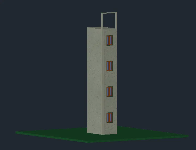
3D view of building facade after rendering (distant light is also applied)
PROBLEM 3 :
AIM : To create isometric 3D view of staircase using AutoCad
PROCEDURE :
- Set units to engineering
- Set units of dimensions to engineering
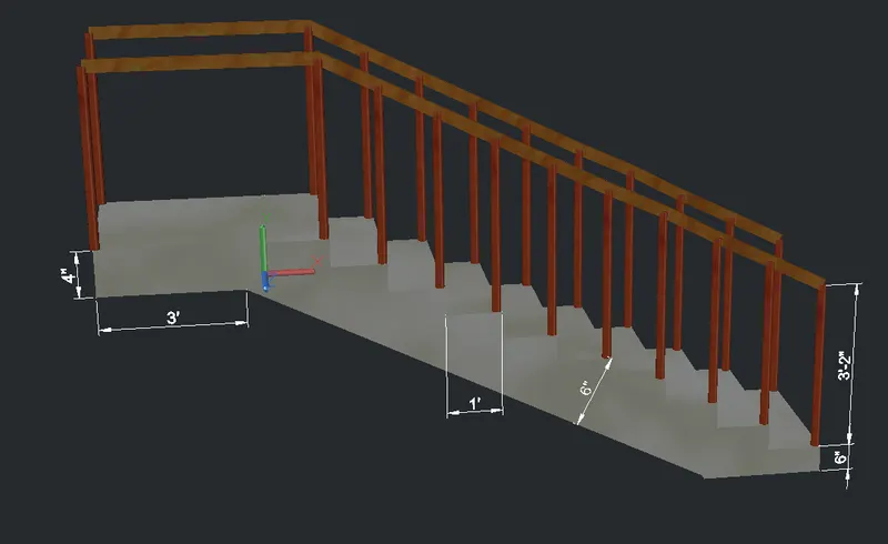
- Draw a rectangle of size 3' x 1' and extrude it to a height of 6" (rise)
- Draw 8 more similar solid elements and place one above other to create steps
- Draw a line below staircase (on both sides) at a distance 6" ( change UCS accordingly while drawing the line)
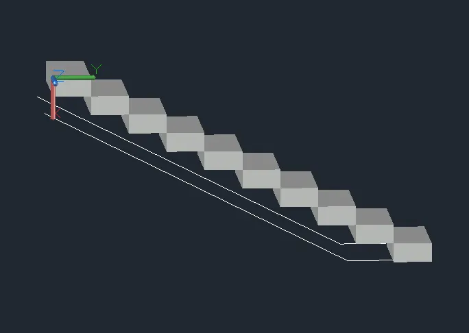
- Create landing by drawing a rectangle of size 3' x 3' and extrude it to a height of 4"
- Create a region below the stair case as shown below
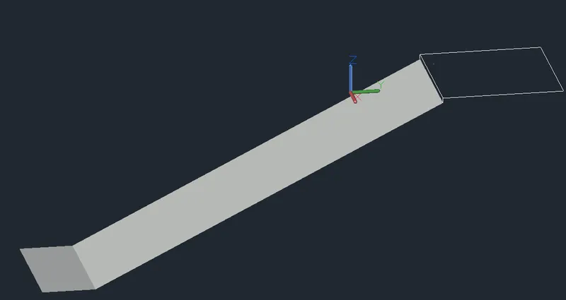
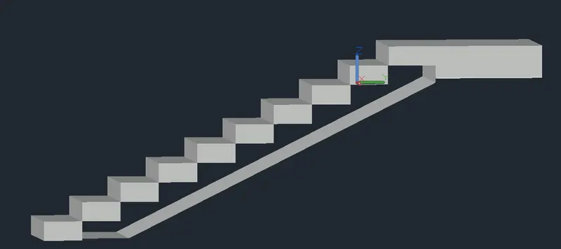
- Using presspull tool area below the stair case is pulled down to the floor level
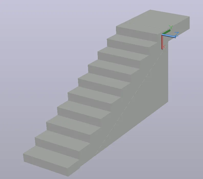
- Now using slice tool, slice the area below stair case
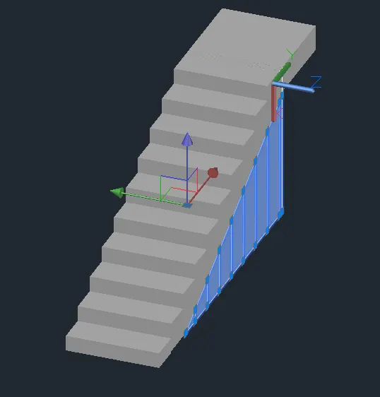
- Remove the unnecessary solid elements
- Create a cylinder of radius 1" and height 3'2" and place it each step on at a distance 1"
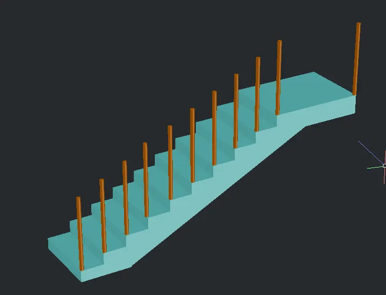
- To create hand rail
- Connect all the cylinder using a line
- Draw a rectangle of size 2" x 2" separately and convert to a region
- Using sweep tool select the region and path as line, create hand rail
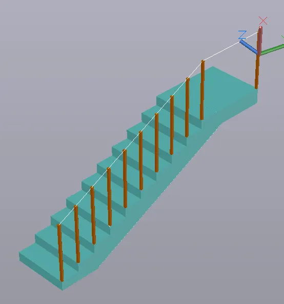
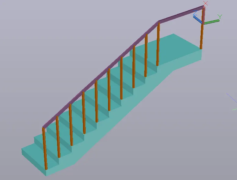
- Copy balustrades and hand rail and place it on other side also
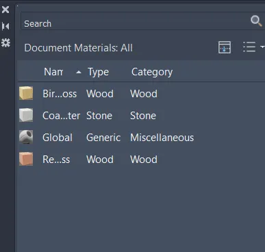
- Now open material browser in visualize tab
- Assign materials to following elements
- Stair
- Hand rail
- Balustrades
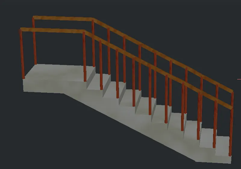
RESULTS :
Isometric 3D view of staircase is created
PROBLEM 4 :
AIM : Create the 3D view of a Wall with spread footing
PROCEDURE :
- Set units to decimal
- Set units of dimensions to decimal
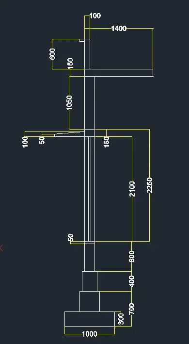
- Draw rectangles of size 1000 x 300, 400 x 400, 300 x 400 and 200 x 600 one above the other
- Draw a rectangle of size 600 x 2100 for window
- Draw sunshade of length 600mm and varying height as 50 and 100 mm
- Draw a rectangle of size 600 x 1050
- Draw a rectangle of size 1400 x 150
- Draw parapet 100 x 600 and coping by drawing a rectangle 100 x 50
- Create regions separately
- Extrude elements separately to a height of 7500 (except 2100 x 600 region and sunshade)
- Draw a rectangle at top (in the gap formed) and create a region
- Extrude this element towards down to a distance 3300
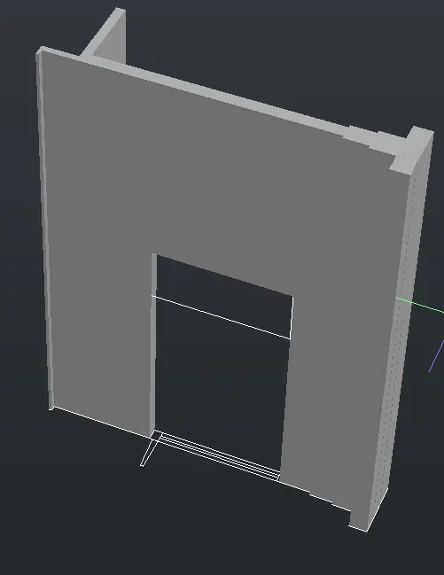
- Move elements in the bottom to a height 3300
- Extrude the remaining area to a height of 3300
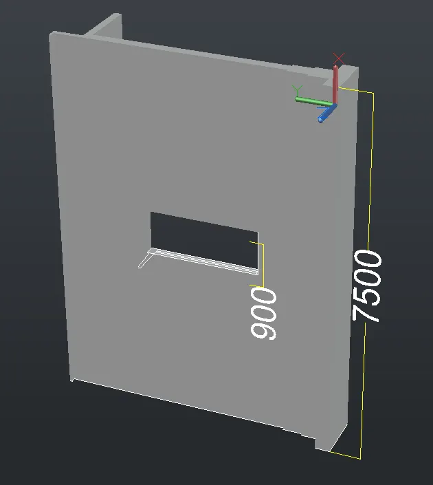
- Create region in sunshade and extrude the region
- Create layers of footing, wall foundation, wall, parapet, coping, roof, sunshade, door frame and assign it accordingly
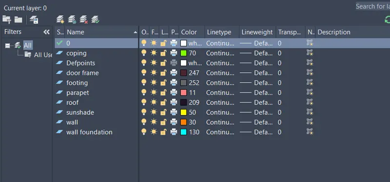
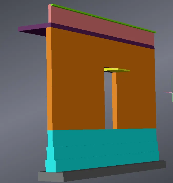
- Now open material browser in visualize tab
- Assign materials to following elements
- Footing,
- Wall foundation
- Wall
- Parapet and Coping
- Roof
- Sunshade
- Door frame
- Now go to render environment and exposure in render tab
- Switch on the environment and select image based lighting : plaza
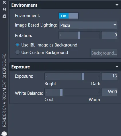
- Now click on render to size for rendering process and save the image
RESULTS :
3D view of a Wall with spread footing is created
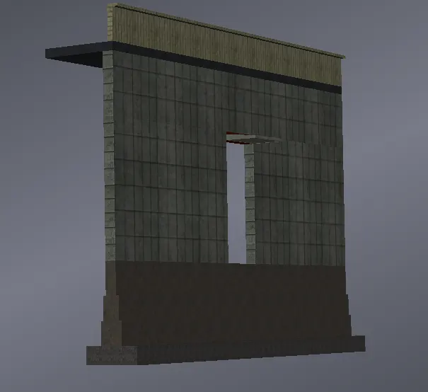
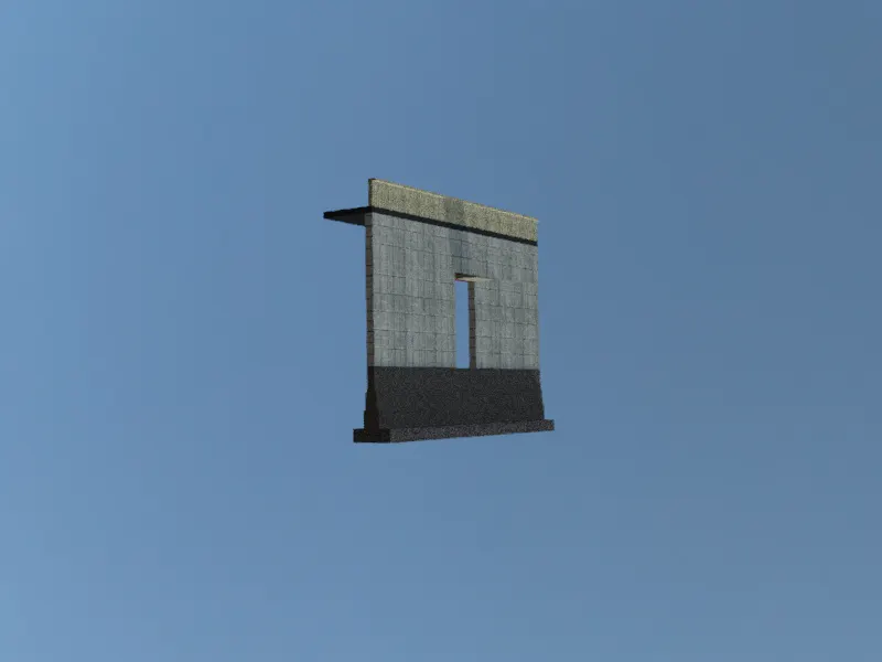
3D view after rendering process