Creating 3D Isometric view of various structural elements in AutoCAD
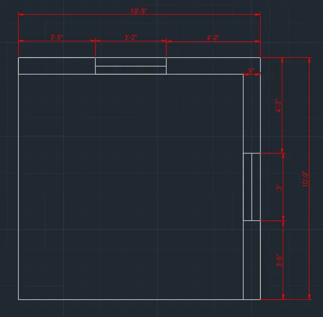
1. Create a 3D Isometric View of the building with plan and elevation given.
Aim: To Create a 3D isometric view of the the building with plan and elevation using Autocad
Procedure:
- In the command prompt type units >engineering>0'-0"
- In the command prompt type limmax>100',100'
- In the command prompt type limits >0',0'
- In the command prompt type zoom > a
- Go to the top view
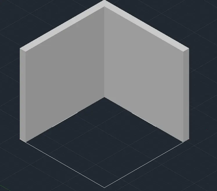
- In the command prompt type l to draw the lines of distance 10'-9" , 3',3-2" and thickness of 9"
- Now, using the dimlin command provide the dimension.
- Now hide the dimension layer.
- Then type BO command to create the boundary region for the walls and then extrude it.
- Go to right view and draft the rectangle using rec command
- Then go south west isometric view and extrude it to 9"
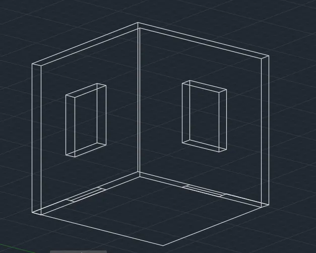
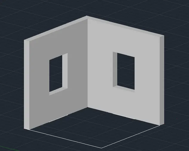
- Using sub command subtract the windows
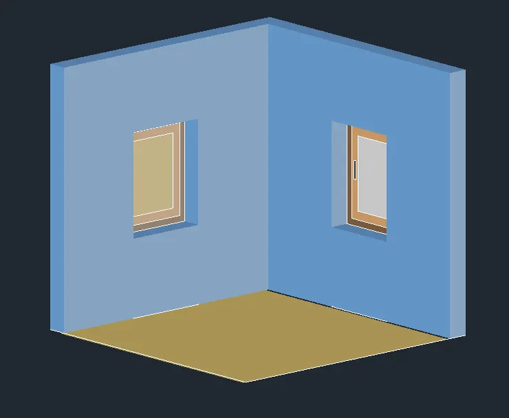
- In the command prompt type h to hatch the windows
- In the command prompt type rec anld l to give the window detailing
- Now place the windows on subtracted area for windows.
Result:
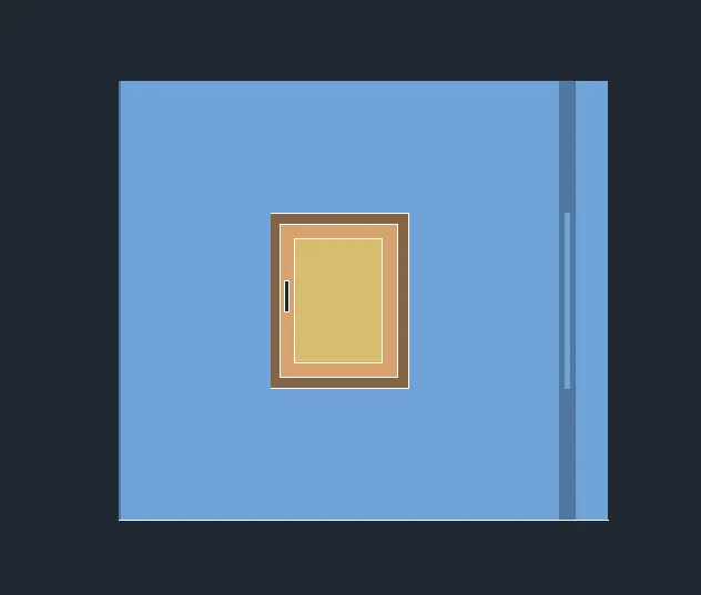
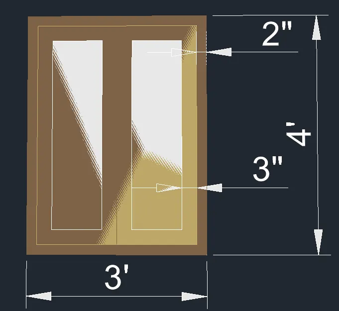
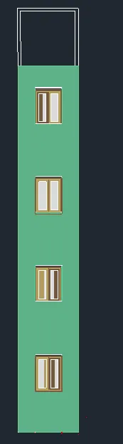
2. Create the 3D View of the Building Façade as given in the plan and elevation. Also, see the detail of
the window.
Aim: To Create the 3D view of the Building facade as given in the plan and elevation
Procedure:
- In the command prompt type units >engineering >0'-0"
- In the command prompt type limmax >100'.100'
- In the command prompt type limits >0',0'
- Go to the top view
- In the command prompt type l and draft the desired lines
- Now using dimlin command provide the dimensions and using the mtext command provide the texts.
- Now hide the dimensions and texts and hatch to create the isometric view and elevation of the plan.
- So for that initially create the boundary region using the boundary command.
- Then extrude it upwards at a height of 40'10".
- Now create the windows at its required positions.
- Convert the figure to shaded view.
- Then draw a rectangle at the window position and convert it to a boundary region and then copy it to the window positions.
- Then extrude it to complete the 3D wall.
- Then using union command unite all the different components.
- In the right view the window is drafted usings lines and rectangle commands
- Now place these windows in the front view of the structure created.
- Change the view to shade as needed.
Result:
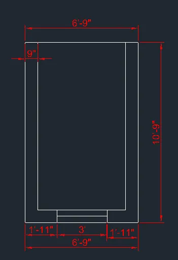
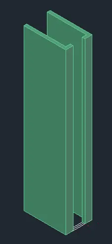
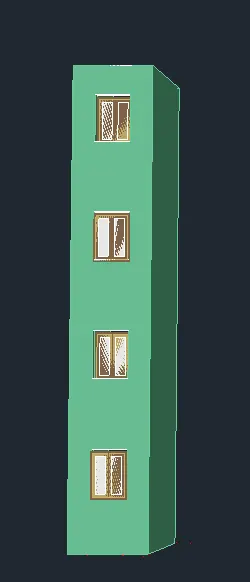
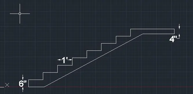
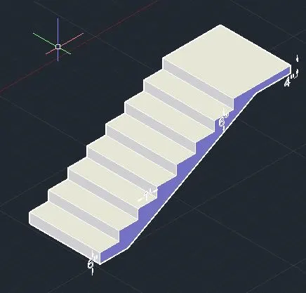
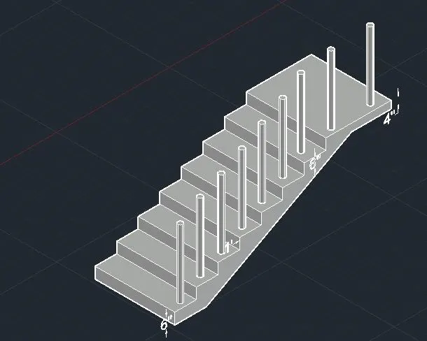
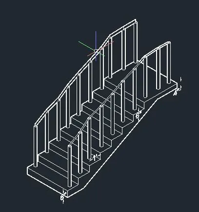
3. Create the ismoteric 3d view of a stair with railing as shown in the plan and elevation. Assume the
size of the balustrades and the hand rails.
Aim: To create the isometric 3d view of a stair with railing as shown in the plan and elevation using 3D autocad software
Procedure:
- In the command prompt type units >engineering >0'-0"
- In the command prompt type limmax >100'.100'
- In the command prompt type limits >0',0'
- Go to the top view
- In the command prompt type l and draft the desired lines
- In the top view the plan is created
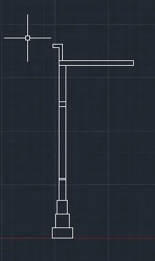
- Now, move to front view and create the side elevation of the staircase.
- This is done using the line command.
- The riser is taken as 6" and the thread is taken as 1'.
- Now, this portion is changed to a region.
- Then extrude it at a distance of 4'.
- Now in the command prompt type circle of diameter 2"
- exturde to a distance of 3'-2"
- In the command prompt type l and join the ralings
Result:
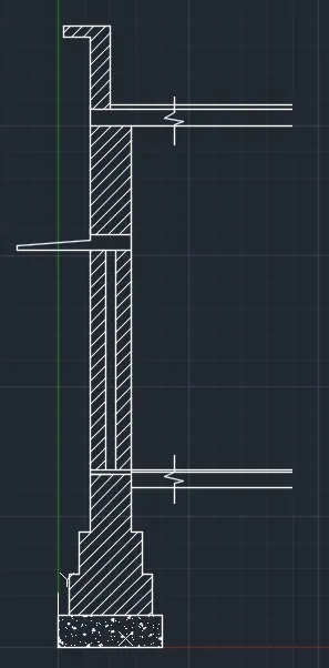
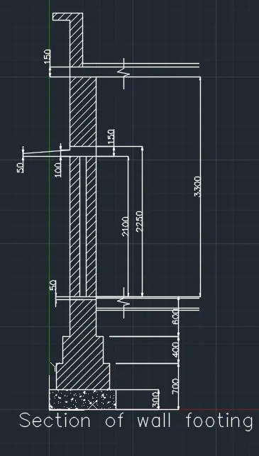
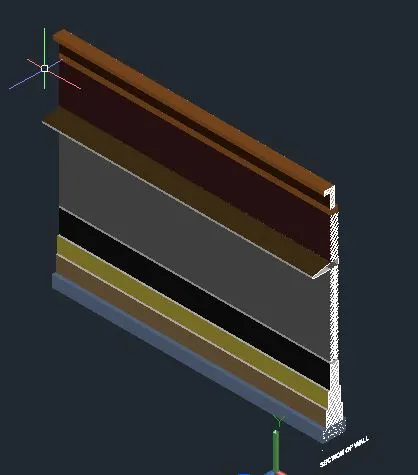
4. Create the 3D view of a Wall with spread footing . Create the Door opening only. Assume the size of
the parpaet and the coping. See the plans and elevation for the details. Also, create a rendered view of
the model with materials as of your choice.
Aim: To Create the 3D view of a wall with spread footing and to also create a door opening using autocad
Procedure:
- In the command prompt type units >0'-0" > engineering > inches
- In the command prompt type limmax >100'.100'
- In the command prompt type limits >0',0'
- Go to the front view
- In the command prompt type l and draft the desired lines
- In the right view the plan is created
- Then provide the appropriate hatchings using the hatch command
- Also Provide the dimensions using dimlin command
- go to the south west isometric view
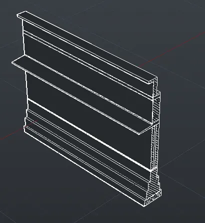
- In the command prompt type extrude and extrude the plan
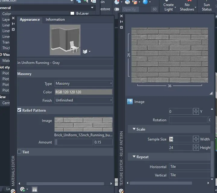
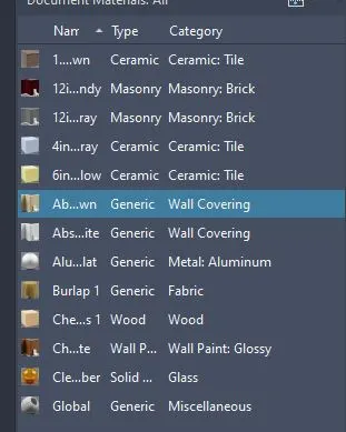
- In the ribbon bar >visualization> material browser > at the material to each element
- In the Ribbon bar > visualization>render to size and choose the material browser and then assign materials to each element.
Result: