Creating 3D Isometric view of various structural elements in AutoCAD
AIM : To draw the 3d isometric view of:
1. Building given plan and elevation
2. Facade of a building
3. Stair
4. Spread footing
COMMANDS USED:
1. Extrude - To give height to a surface or giving distance or hright in z axis of an object in x y plane so that i becomes 3d.
2. Offset - To draw the offset line. Command "O"
3. UCS - Command "UCS" . To change the UCS so as to draw in that face ie, x and y plane will be made in the selected face so that it is easy to draw in that plane. Default is UCS world.
4. Box- To create a box . It is found in the ome toolbar.
5. Union- Command :UNION" . To make diffrent 3d object ointo a single enitity.
6. Subtract - Command "SUBTRACT" . To subtract one 3d object from another . First select the object from where to be subtracted then the object which needs to be subtracted.
7. Move - Command "M" . To move an object in a particular axis . Coordinates also can be given for moving an object after the command.
8. 3d orbit- Coomand "3DO" . To rotate the object so that we can view around 360 degree.
9. Boundary - Command "BO" . From this command also region can be created . If the encircled region is created by different lines , boundary is used. select region in the dialogue box and click on the internal point where region is to created and then extrusion is done.
10. Sweep - to make 3d of an object in a given path. In toolbar select sweep , seelct the object to be swept then the path.
11. Render - Command "RR" - to see the view of the object after materials are applied.
12. Material Browser - Command "MAT". To apply the materials for different objects.
1. Create a 3D Isometric View of the building with plan and elevation given.
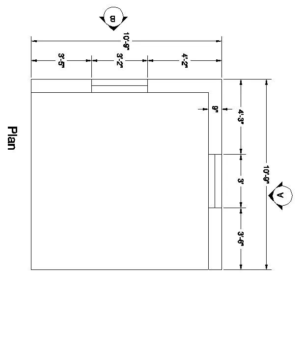
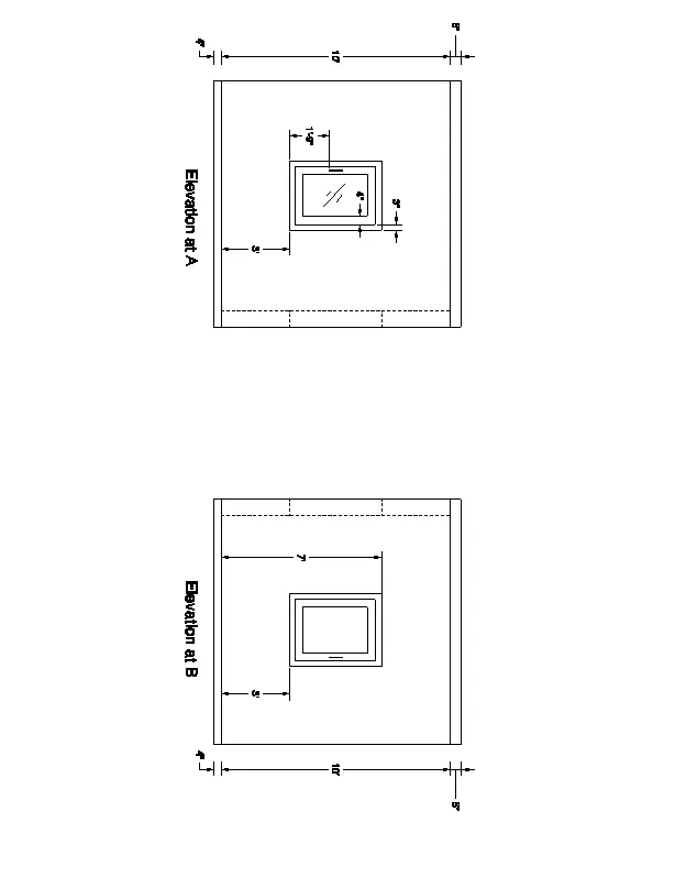
Aim : To create 3d isometric view of a building with plan and elevation.
Procedure:
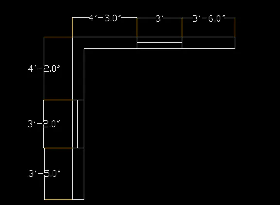
Step:1 Drawing the plan:
In the top view,
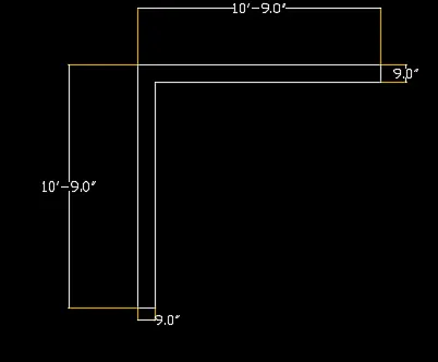
- With line command ,draw a lne of 10'9" vertically and horizontally such that a L- shape wall s formed.
- Offset 9" line from the two lines.
- Give offset of 4'2" from the corner of the wall.
- Again give offset of 3'2" from that line for the window.
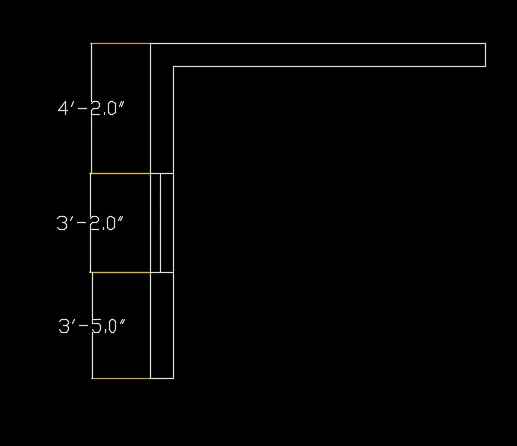
Step :2 Draw the window
- Similary on the other side also, offset 4'3" from the corner ,3' for the window.
Step:3 Making it 3d
- Commadn"3do" fro 3d orbit and orbit the view so that 3d is seen
- Now create a region in the wall area by command "BO" for boundary.
- Go to shaded view to see the boundary
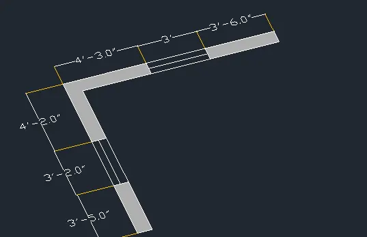
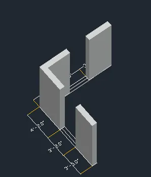
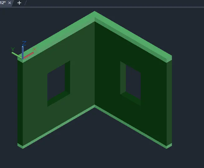
- Now extrude the region , givng a height of 10'. Command "EXTRUDE" , give height =10'.
Step :4 Creating opening for windows:
- Draw a rectangle over the window portion.
- Extrude it to 3' ie to sill level.
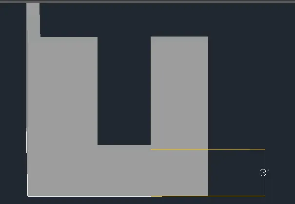
- Similarly create a rectangle at the top.
- Extrude it downwards to a height of 3' from the top.
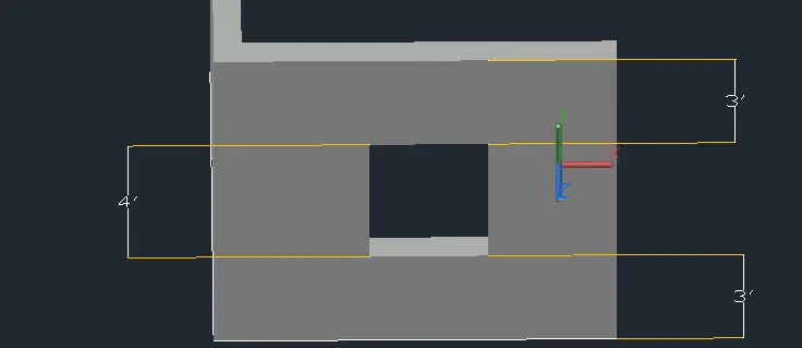
- Union the walls by command "union" - select all the walls.
- Similarly create the window on the other side wall.
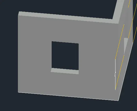
- Create layer for walls and place it in wall layer.
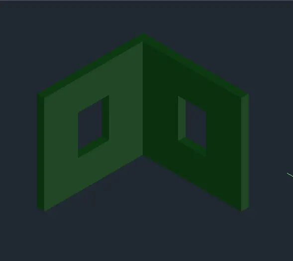
- In the top view, by polyline create an outline of the plan.
- Create a region by boundary.
- Then place it in the bottom by move command "M" @0,0,-10'.
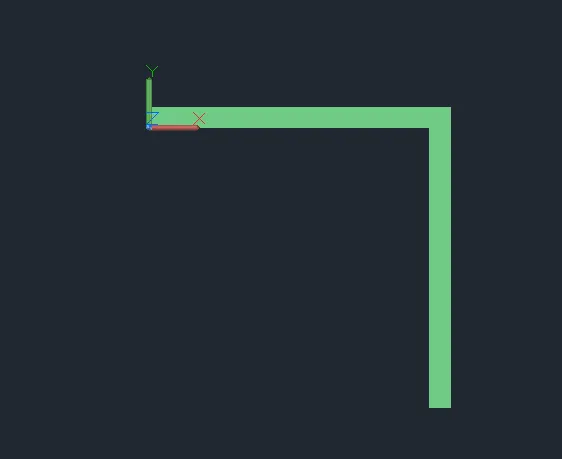
- Extrude it downwards to a height of 4".
- Similarly create a polyline at top and extrude it to a height of 6".
Step: 5 Creating elevation in 2D:
a. Elevation at A-A
- Draw the elavation A from the plan in top view.
- Project the wall line from the plan and also the window lines.
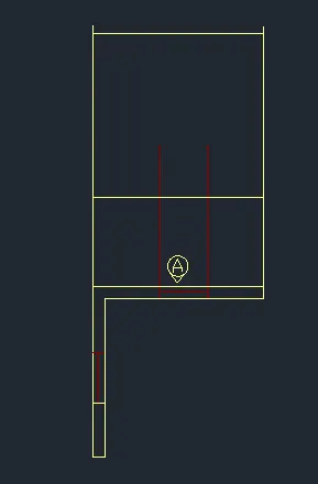
- Give the height as 10' ,then offset lines of 3' from bottom and top to create window
- Then offset 3" for the frame and 4" for the mullion.
- Also offset 4' downwards for plinth and 6'upwards for the roof slab from the 10'.
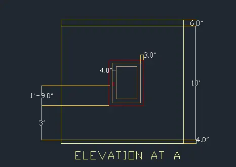
- Create different layers for frame, mullion and glass.
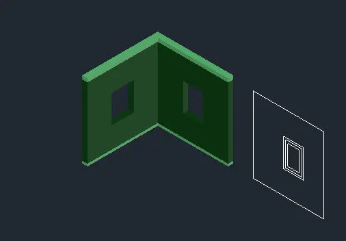
Step:6 Creating 3d of elevation:
- Place the 2d drawing in alignment.
- Group the elavation by group command , so that all will be in a single selection
- By 3d rotate rotate the image making it parallel to the 3d wall. seelct the axis then give angle as 90 degree.
- Place the 2d elevation in the 3d object by snapping the corner and then move it to the side parallel to the 3d wall face.
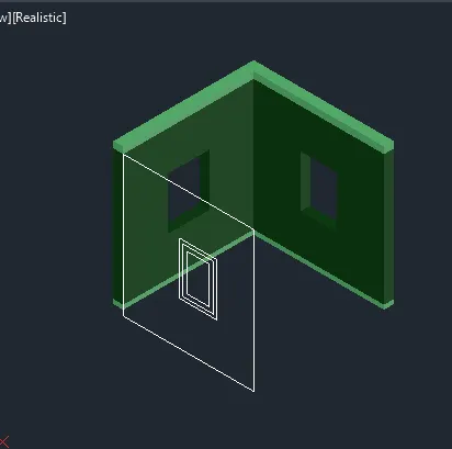
- Place the 2d elevation in the 3d object by snapping the corner and then move it to the side parallel to the 3d wall face.
Step:7 Creating frame, mullion and glass of window:
- Copy the window from plan and place any where to make a window.
- By "bo" command craete a region from the frame.
- Explode it and delete all other except window.
- If region is created fully, subtract , select larger region then smaller one.
- Extrude the region, giving -7" value.
- Similarly create region for mullions by "BO"- boundary command.
- Extrude it by -5".
- Create a region for glass by creating rectangle boundary if boundary is not there
- Extrude it by -3"
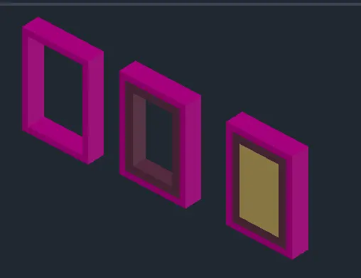
- Now for making window move -2", -1" the glass, mullions from frame
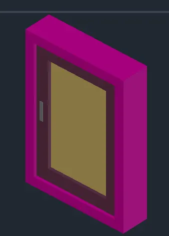
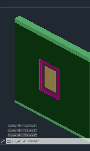
- Move the 3d window to the opening of te window craeted in 3d model.
- Make sure that the mullions is inside the frame and glass is inside the mullions ( after a distance from the frame mullions are provided likewise glass)
Isometric view of elevation A
Step:8 Creating elevation B
b. Elevation at B-B
- Go to top view and extend the lines from the plan .
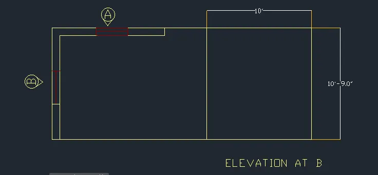
- Draw 4" offset at ottom and 6" at top.
- Draw window at a height of 3" from the bottom and offseting 7' from bottom to get the top of the window.
- Give the thickness by offsetting the rectangle by 3" for frame and 4" for mullions.
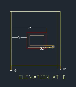
Step : 9 Creating 3d of elevation at B
- Place the 2d elevation parallel to the 3d elavation in top view
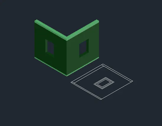
- In 3d view, Rotate the 2d elavation such that the 2d elavation is in parallel to the 3d face.
- For that rotate 3d command , select y axis then give the angle as 90 degree.
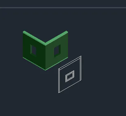
- Place the 2d on the face of 3d , then move the 2d image paralle to the face.
- Delete the wall and keep only the window for extruding.
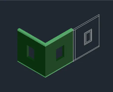
Step:10 Creating frame, mullion and galss of window on elevation B
- By "bo" command craete a region fro the frame.
- If region is not created , create a reactnagle through the outline and give region
- If region is created fully, subtract , select larger region then smaller one.
- Similarly create region for mullion and the glass with respective layers.
- Extrude the frame -7" mullion by -5" and glass by -3".
- Extrude the handle also.
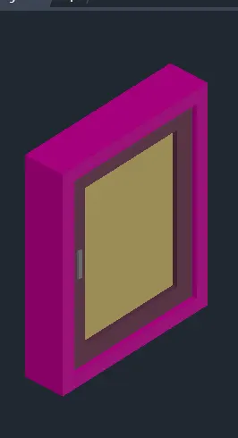
- Place it in the 3d wall.
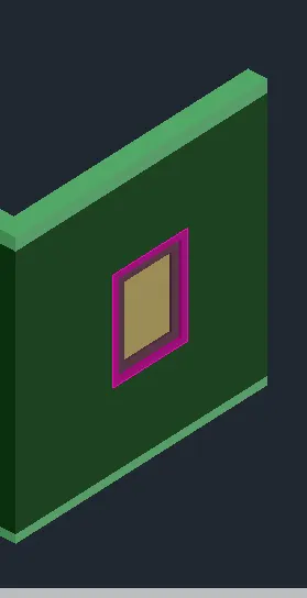
Isometric view of elevation B:
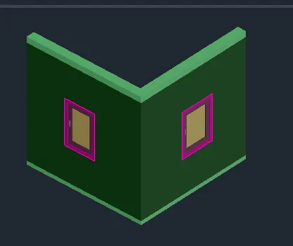
Result:
2. Create the 3D View of the Building Façade as given in the plan and elevation. Also, see the detail of the window.
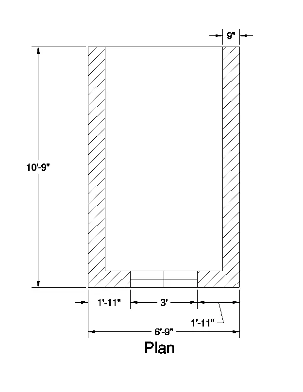
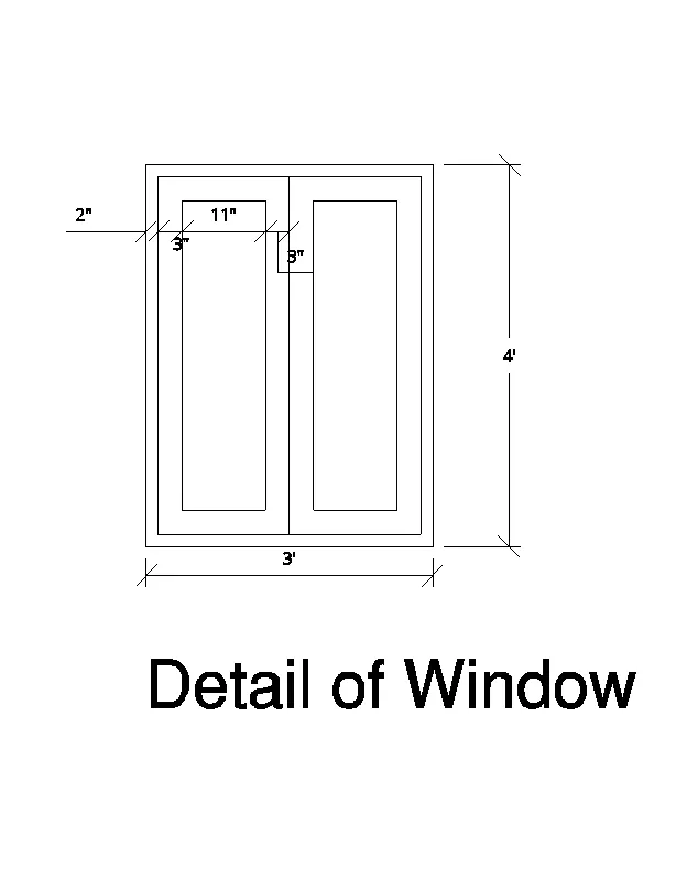
Aim :Creating 3d view of builidng facade
Procedure:
Step:1 Creating the plan:
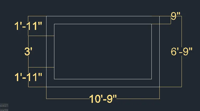
- With rectangle command create a rectangle of 10'9" and 6'9".
- Offset 9" for the wall thickness.
- Create window of 3' width.
Step:2 Extruding the height:
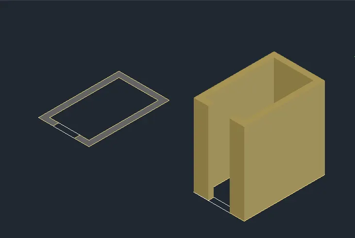
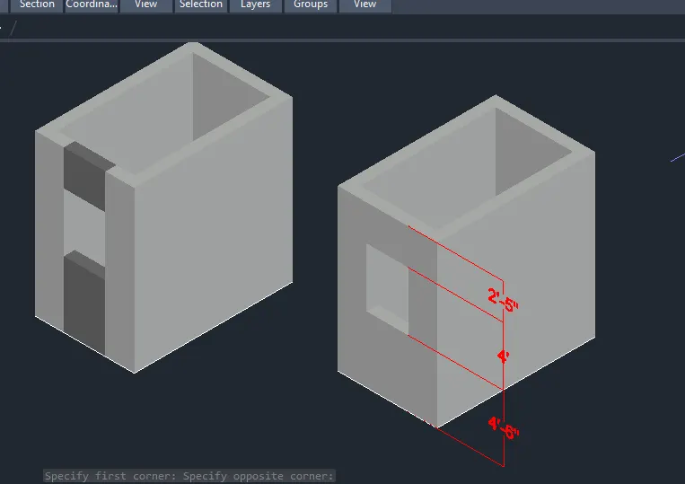
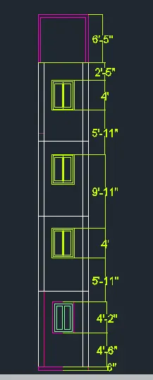
- As the sill level height is given as 4'6" and window height as 4' ,and top height from the window is 2'5".
Total height of one floor =2'5"+4'+4'6" =10'11"
- Create a region in the part of wall for extrusion by command "BO".
- With extrude command extrude the created region giving a height of 10'-11".
Step:3 Creating windows:
- Create a rectangle at the bottom of the window position.
- Extrude it to a height of 4'6".
- Similarly create a rectangle at the top and extrude 2'-5" downwards.
- With union command , make all the walls in union.
Step:4 Creating windows
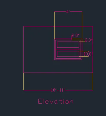
- Create the elevation of the plan in 2D. -top view.
- As the window is in side of plan ,side elevation is taken by projecting lines from the plan
- Window detailing is done , 2" offset for frame and 3" for mullions, then 1.5" will be the glass area.
Step: 5 Creating window in 3D
- Group the elavation.
- Place the elvation in front of the 3D image.
- With 3drotate rotate the elavation by 270 degree.
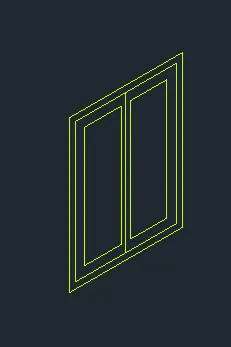
- Place it in parallel to the face and move it to side .
- Ungroup and delete the walls and keep only the window...
- Create region in the frame of window by "BO" command , making frame as a layer.
- Extrude -5" for the thickness of frame.
- For mullions create another region in different layer and extrude -3".
- For galss also create a region and extrude-1.5".
- Now for making window move -2", -1" the glass, mullions from frame.
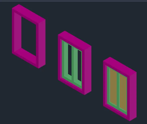
- Move this object and place the window on the gap in 3d wall.
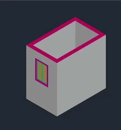
Step:6 Creating floor:
- Go to top view and create a rectangle
- Extrude it by 5".
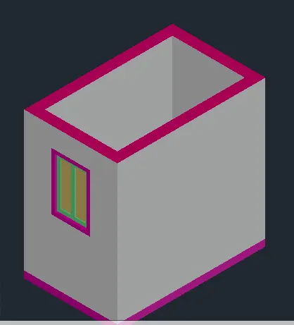
Step:7 Apply Material to window:
- Apply material to by using command "MAT" which is open material browser.
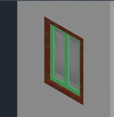
- Selecting material from Aurodesk library for category of wood.
-Select window and Select material cocobolo, drag material on selecting object.
- similarly for window create a new material from document select category, then select image which is glass texture- select glass object and apply it.
Step:8 Creating 2nd floor:
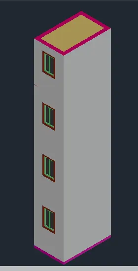
- Group the created model and copy the created 1st floor on top .
- Copy the 4 floors as such.
Step :9 Creating top frame:
- Type "UCS" as command and place the ucs on the top face of building
- Draw a rectangle with dimensions 9" x 4".
- Extrude it by 6'5".
- Copy it on the other side .
- Again create rectangle on top face .
- Extrude it by -4".
- Create a roof on top by rectangle and extruding it .
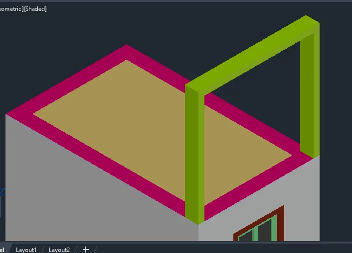
RESULT:
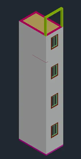
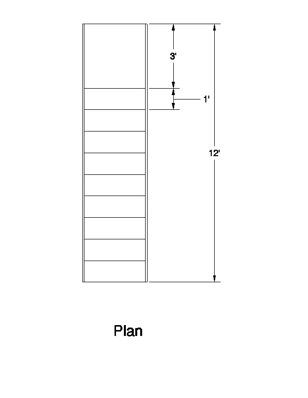
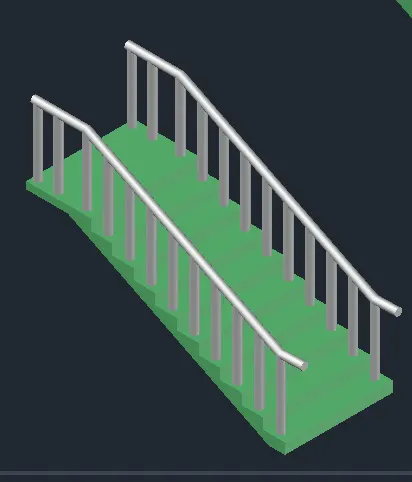
3. Create the ismoteric 3d view of a stair with railing as shown in the plan and elevation. Assume the size of the balustrades and the hand rails.
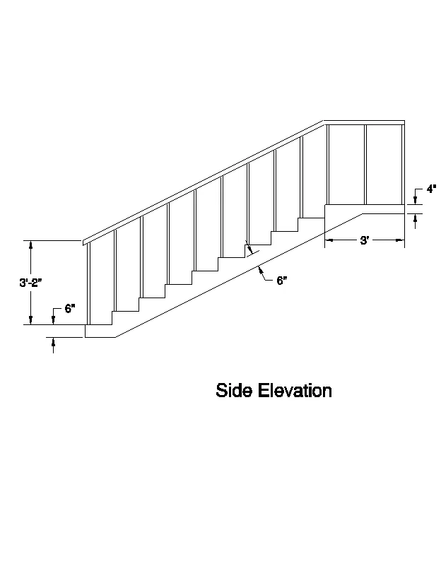
Aim : To create 3D view of stairs.
Procedure:
Step: 1 Creating steps
- With tread as 1' and riser as 6" , draw the steps in the top view 2d wireframe.
- Landing is 3' and the waist slab is 6" thickness .
- Join all these to form the section of the stair.
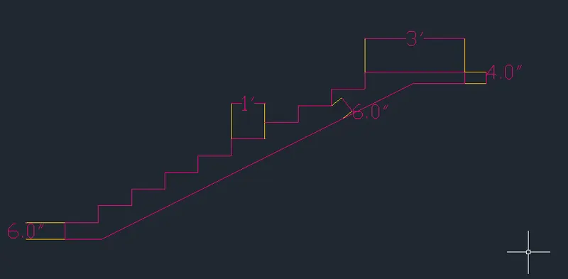
Step:2 Extruding the stair
- Create a region by boundary command.
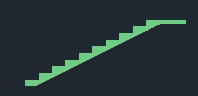
- With 3d orbit place the section in such a way that it is visible.
- Extrude 3' towards the side as 3' is taken as width of the stair.
- With 3d rotate -select x axis and give the value 90 degree.
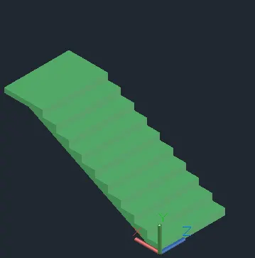
Step:3 Creating balustrades and handrails
- Place the UCS on the tread and ceate a circle of diameter 2" and height 3'2".
- Copy it in all the treads and also in landing.
- For handrails, create a polyline joining the balustrades by "3dpoly". 3d polyline
- Create a circle of rdius 2" and sweep it by selecting the circle and then the polyline.
- Using 3D mirroring place handrail another side also.
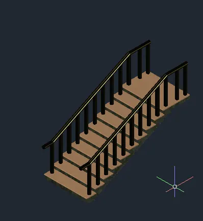
Step:4 Apply material to staircase:
- For making thred platform draw rectangle 5' x 1'2" and 5' x 3'2".
- Make a region of this rectangle by "REGION" command.
- Extrude these rectangles 1"
- For fillet front edges by using fillet having radius is 0.5"
- Apply material to by using command "MAT" which is open material browser.
- Selecting material from Autodesk library for category of wood.
- Select these rectangles and Select material Beech, drag material on selecting object.
- Now place this rectangles on stairs by using copy option
- Similarly apply material for handrail
- Select this handrail and Select material Foil gold, drag material on selecting object.
- Also apply material to slab of staircase i.e. cementeous material.
- Select realistic view.
RESULT:
4. Create the 3D view of a Wall with spread footing . Create the Door opening only. Assume the size of the parpaet and the coping. See the plans and elevation for the details. Also, create a rendered view of the model with materials as of your choice.
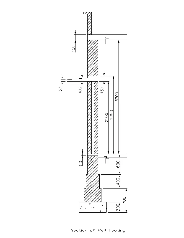
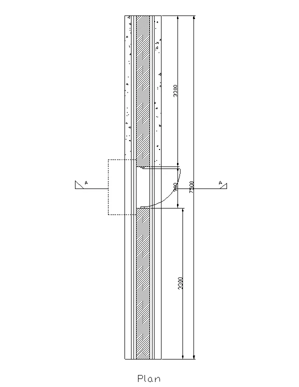
Aim: To draw 3d view of wall with spread footing
Procedure:
Step 1 : Creating the plan - wall
- Open the Autocad in metric and set the limits and zoom all.
- Draw the plan offoundation
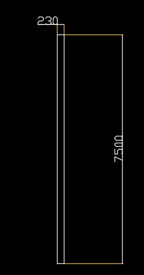
- With line command draw a vertical line of 7500mm and 230mm width
Step 2: drawing the foundation in plan
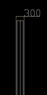
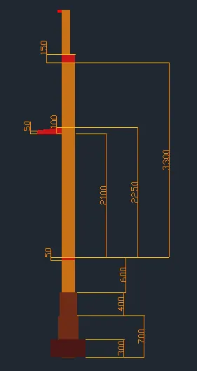
- Draw a centre line in wall and offset 150mm on both sides so that the total width is 300mm.
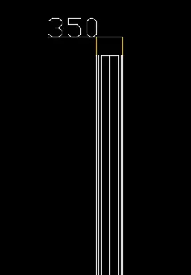
- From the 300mm line offset 25mm on both sides then the total width becomes 350mm
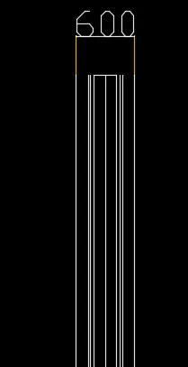
- From the centre again offset 300mm on both sides , the toatal width is 600mm.
- Extend the horizontal line.
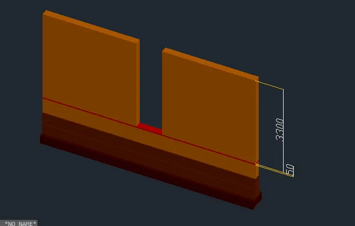
- Offset 3300mmfrom both the sides for the door opening of 900mm.
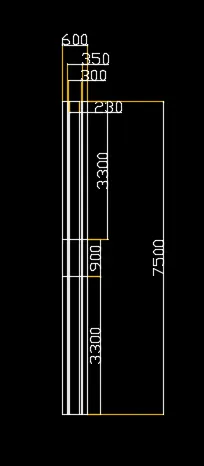
- Create door in the opening by circle and line.
- Hatch the wall , foundation with different hatches.
- ANS 132 for wall , Solid for footing , AR-CONC for bottom P.C.C.
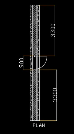
Step 3: Making the 2d plan to 3d- footing R.C.C
- With 3do make a suitable view.
- Make layers for footing-R.C.C , footing -steps , wall and door
- Create a rectangle -profile on top of the plan of footing -R.C.C.,place in the respective layer and copy it.
- Create region by boundary command.
- Extrude it by 300mm.
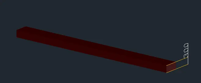
Step 4: Creating footing steps:
- Go to top view and create profile for footing step in 2d plan and copy it and place in 3d plan with the help of snap tool.
- Create region by "BO" command.
- Extrude it by 400mm.
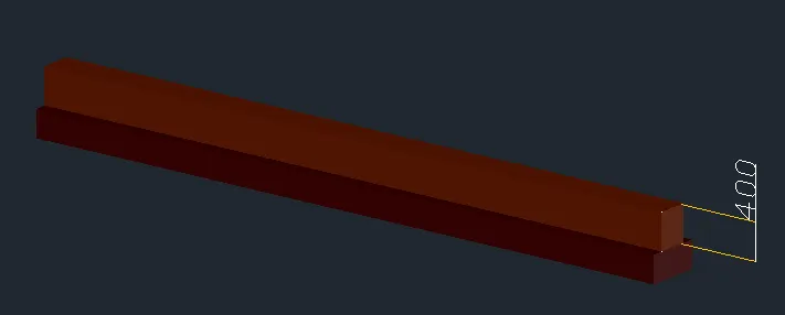
- Again create a profile and place such that the midpoint od 2d profile coincides with the 3d object
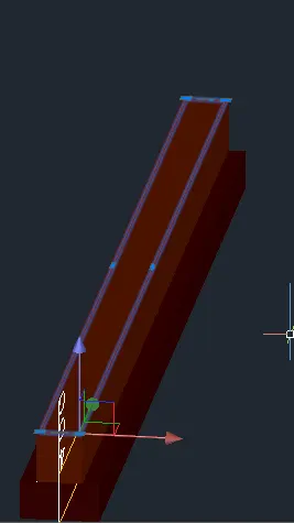
- Create a region and extrude it by 400mm.
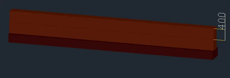
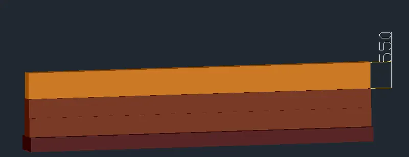
- Now create a profile forfoundation in differnt layer and place it in top of the 3d model.
- Extrude it to a height of 550mm.
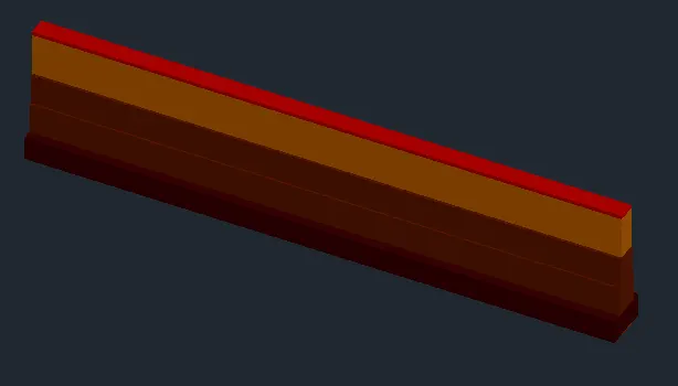
Step 5: Creating floor
- Create a rectangle for floor and extrude it to a height of 50mm.
Step 6: Creating wall
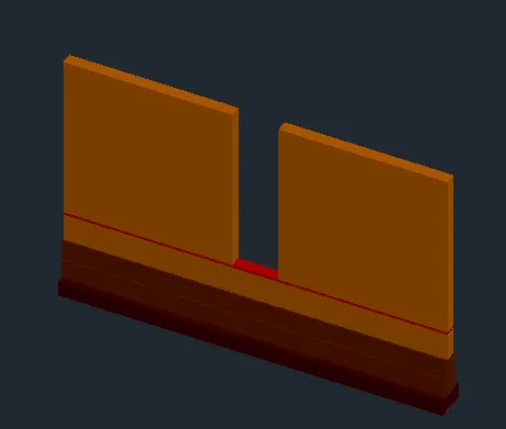
- Now create profile for wall on both sides of door.
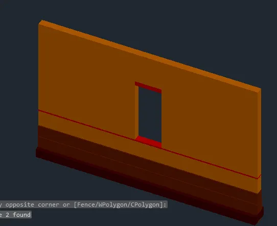
- Copy it and place it in 3 d model and extrude at a height of 3300mm.
Step 7: creating lintel beam
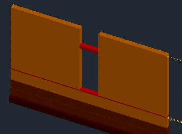
- Create a rectangle profile at top.
- Move it by move command @ 0,0,-1050
- Extrude it at a height of -150mm
Step 8: Creating the top porttion of wall
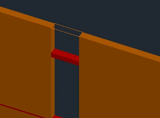
- Create a rectangle at the top face
 .
.
- Extrude to a height of -1050mm.
- With union command , make the extruded part as part of the wall.
Step 9: Creating shade
-Keep the ucs on the side face.
- Draw a horizontal line from bottom of the lintel , then a vertical line 50mm to top.
- On the other side draw a vertical line of 100mm upwards,then join these two points of 50 and 100.
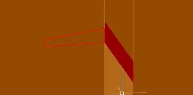
- Group it to single entity.
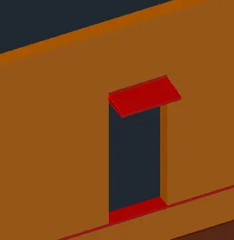
- Create region by boundary command by placing the ucs on side face of the jamb of door.
- Extrude it towards side till the opening.
Step 10: Creating top slab
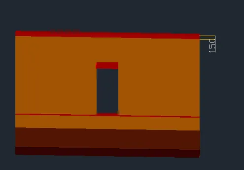
- Create a rectangular profile on top of the wall.
- Extrude it by 150mm.
Step 11: Creating parapet and coping
- Create parapet of width 150mm and height 750mm.
- Create a rectangle of 7500mm and 150mm on top of the 3d model.
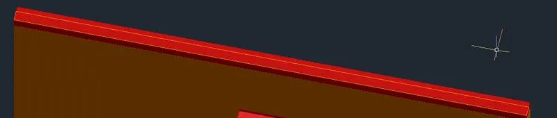
- Extrude it by 750mm.
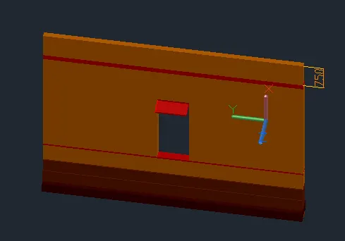
- For coping in the side view place the ucs and draw 40mm width line from the parapet with projection of 60mm.
- Create a region by bo command
- Draw a line on top .
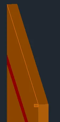
- Use sweep option , select the projection and then the line.
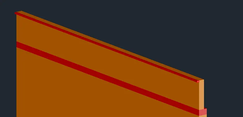
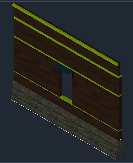
Step 12: Rendered view
- Go to visulaise tab , select "Material browser" .
- For Chajja select from flooring. Make following setting for it.
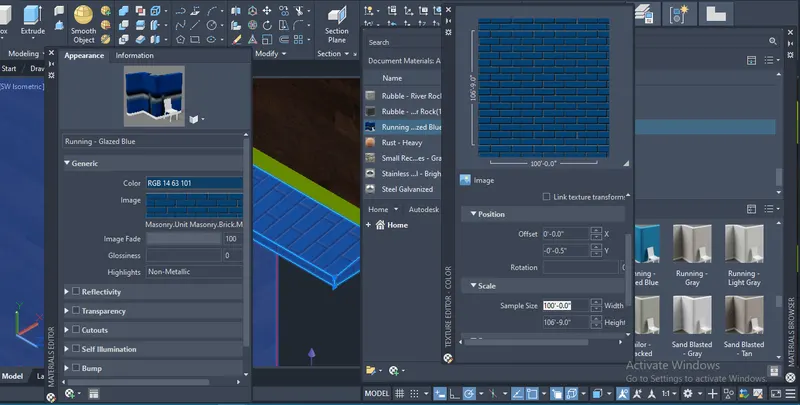
- for foundation , select a stone.
- For wall , select from paint.
- Select each object and give assign to selection
- keep shadows on
- Create a cylinder and give distant light.
- Then click on render or command "RR".
RESULT:
RESULT:
1. 3d view of a building is craeted.
2.3d view of Facade of a building is created.
3. 3d isometric view of stair is created.
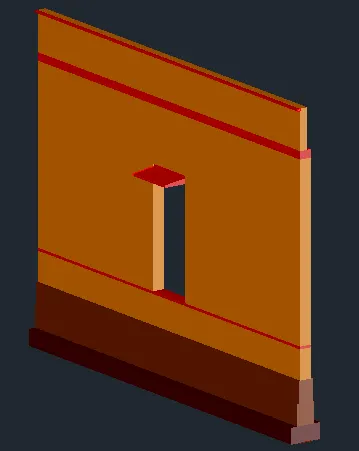
4. 3d view and rendered view of Spread footing is created.