Creating 3D Isometric view of various structural elements in AutoCAD
AIM:
To Create a 3D Isometric View of the building with plan and elevation given.
Introduction :
Various command used while Sketching :
- Line command
- Units command
- Lim max command
- XL command
- Zoom command
- Text command
- Rectangle command
- Copy command
- Dimension command
- Layout command
- Limits command
- Boundary
- 3D Orbit
- 3D rotate
- Extrude command
- Region command
- UCS command
- Camera command
- Block command
- Render RR command
- Sweep command
- Create light command
PRODUCTRE :
STEP 1 :
- GO to START MENU ,select AutoCAD 2018.
- Enter “UNITS” command in the command tab.
- Open “ Drawing units “ dialogue box , Type as “ENGINEERING ” and precision as 00
- Then click units scale to “INCHES ”
- Click “OK”.
- Enter “ LIM MAX” command in the command tab.
- Enter new value for Lim max as 100’.
- Enter “zoom” command in the command box.
- Enter “All” command in the command box.
- Enter “LIMITS” command in the command box.
- Specify lower left corner as “0,0”
- Specify right corner as 100’ , 100’
- Enter “zoom “ command in the command box.
- Enter “ALL” command in the command box.
STEP 2:
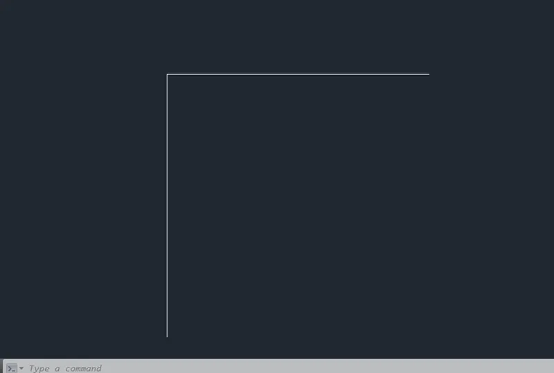
- Enter “LINE” command in the command box.
- Give first specify first point and
- Give next specify point as 10’9” in y -axis
- Give next specify point as 10’9” in x -axis
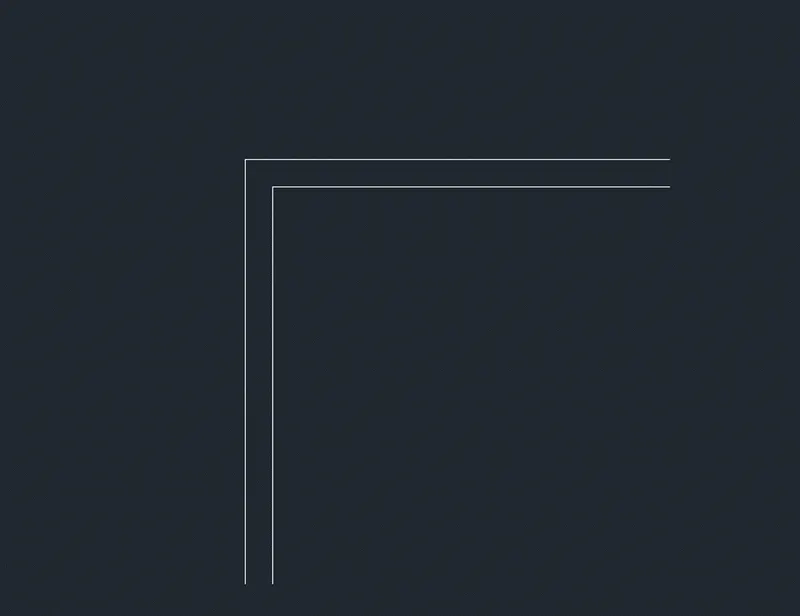
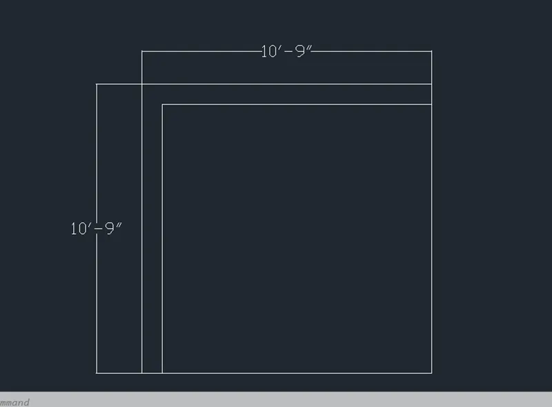
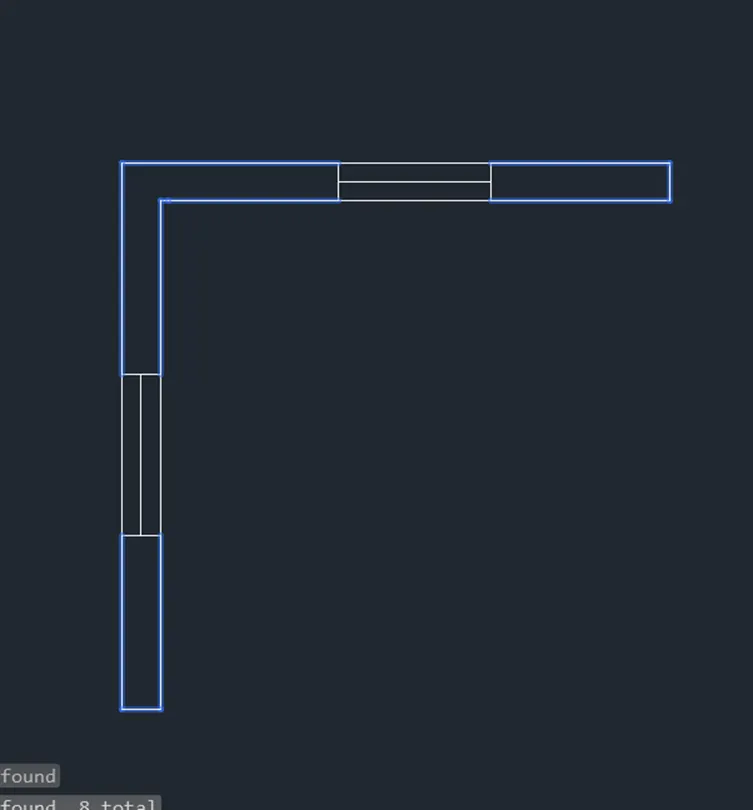
- Enter “OFFSET” command in the command box.
- Give a offset value as 9” from the privies line.
- Create a window from the base line
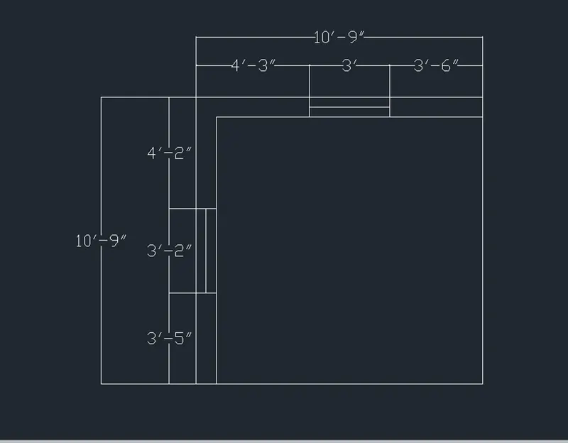
- Enter “OFFSET” command in the command box.
- Give a value from the base point as 3’-5”
- Give a next offset value as 3’-2”
- Enter “OFFSET” command in the command box.
- give a value of 3’-6” form the right side to left side
- Enter “OFFSET” command in the command box.
- give a offset value as 3’ from the previous line
- once we created plan as the drawing .
- enter “JOIN” command in the command box
- select the line as which is shown this drawing and joint the line
- change a view south – west isometric
- Enter “EXTRUDE” command in the command box.
- Select the joint line and extrude as per the drawing
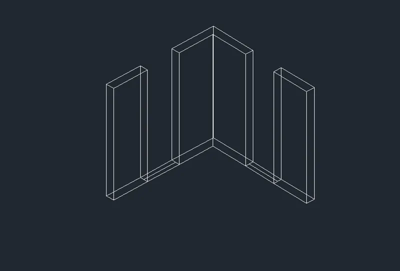
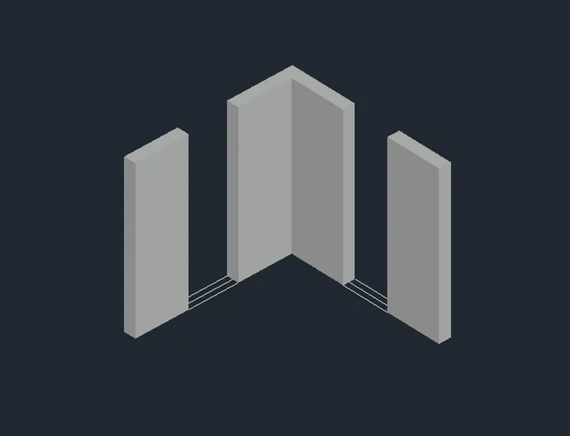
- Enter “LINE” command in the command box.
- Create line in the window location and above the window
- Enter “EXTRUDE” command in the command box.
- Extrude the base of window place and above the window place as the drawing
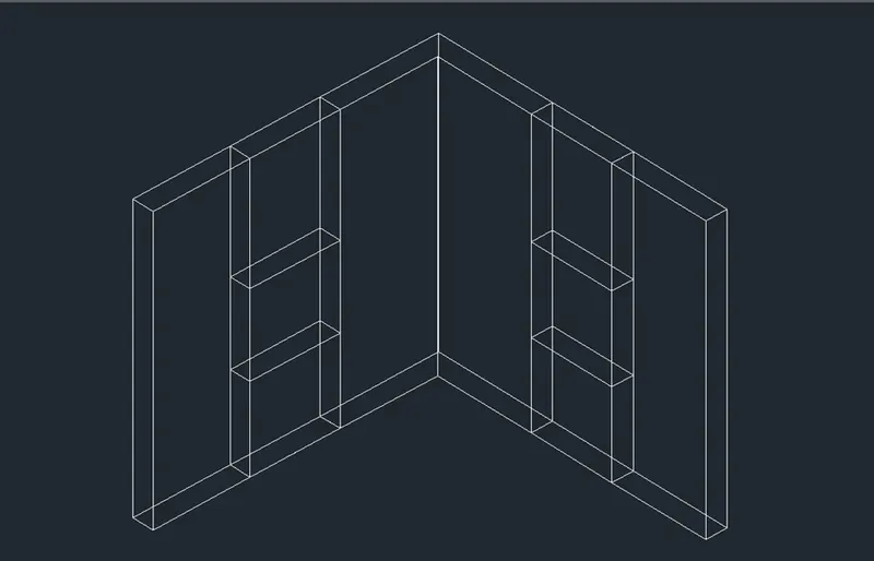
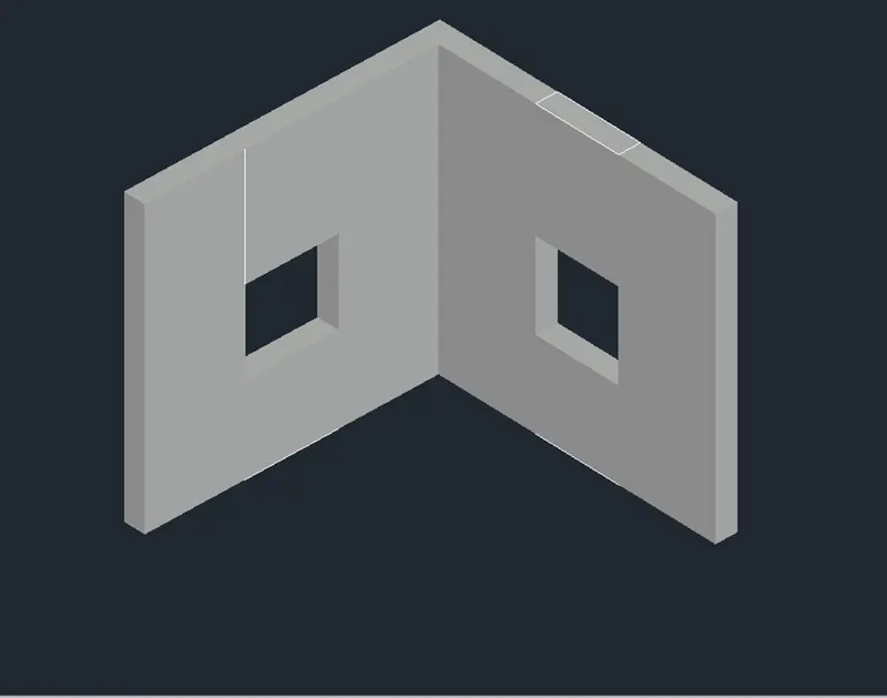
- Enter “UCS” command in the command
- Change the view and create window in 2d
- Go to the layer option in home tap
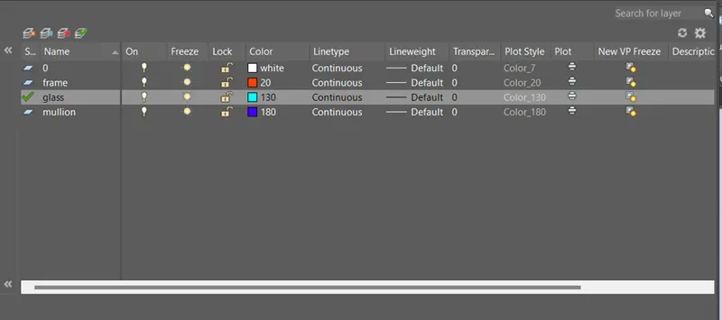

- Create a window in 2d
- Create a , GLASS, FRAME ,and MULLION in the layer option
- Enter “BOUNDRY” command in the command box.
- u will boundary creation as dialoge box ,
- set in region and click the pickup point, change the layer and set current
- select the “Frame” object and , click “ENTER”
- Enter “SUBTRACT” command in the command box.
- Select the large one and select the 2nd one
- Enter “BOUNDRY” command in the command box.
- u will boundary creation as dialoge box ,
- set in region and click the pickup point, change the layer and set current
- select the “ Mullion” object and , click “ENTER”
- Enter “SUBTRACT” command in the command box.
- Select the large one and select the 2nd one
- Enter “EXTRUDE” command in the command box.
- Extrude the window in the frame as 4” and mullion as 3”, glass as 5”
- Enter “MOVE” command in the command box.
- Select the window and move window fix in the wall as per the drawing.
- Enter “DIMLINER” command in the command box.
- Show the dimension as per the drawing
- Change the “USC” show the view as per the drawing.
- Finally show the results .
RESULT:
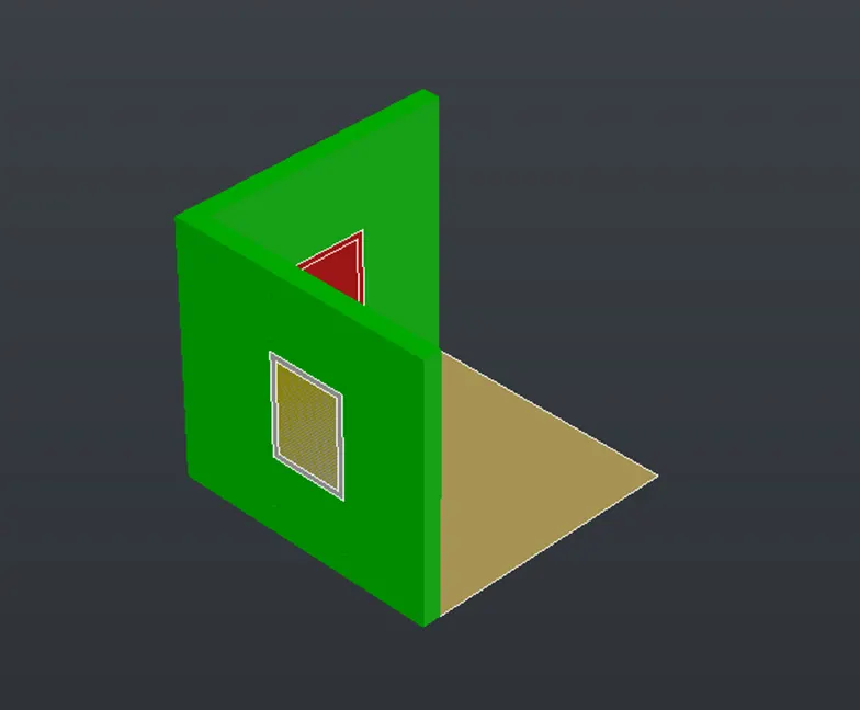
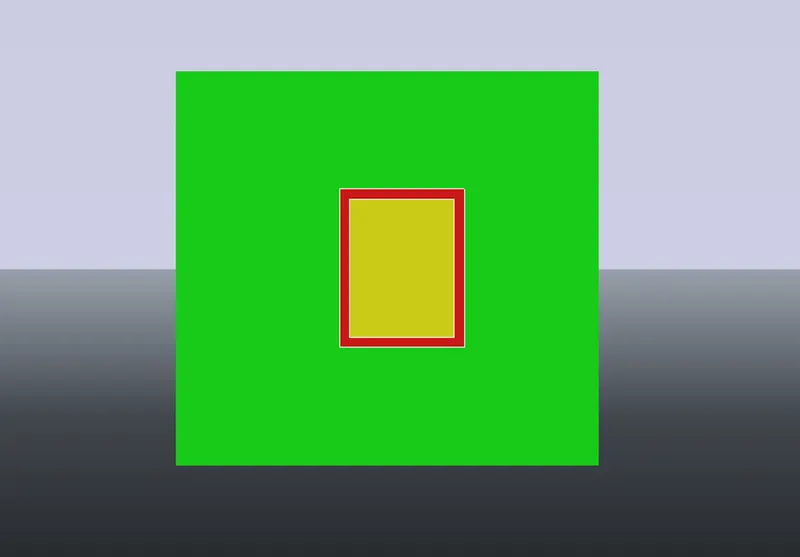
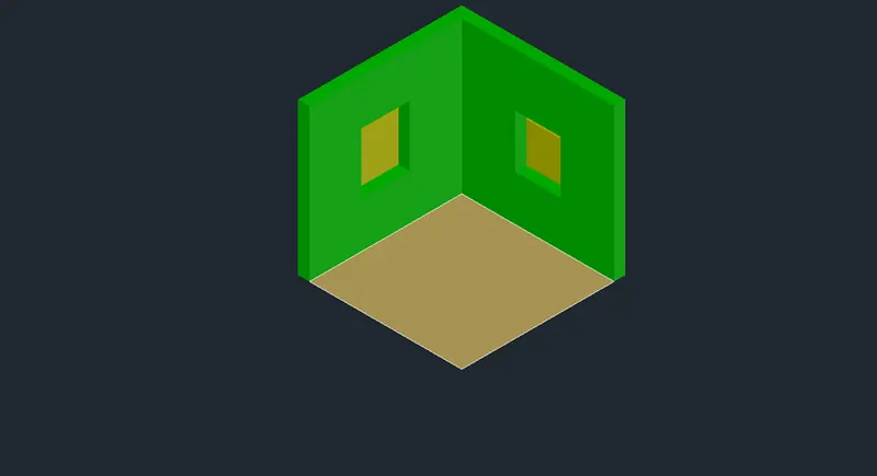
AIM:
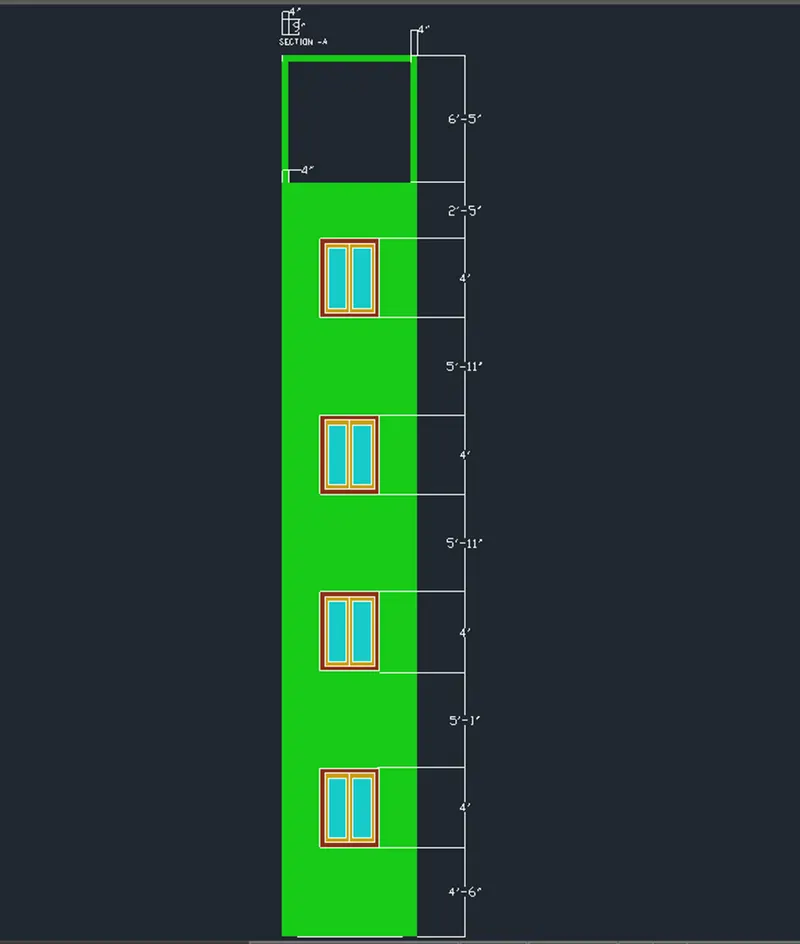
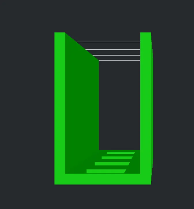
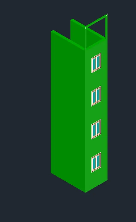
To Create the 3D View of the Building Façade as given in the plan and elevation.
Introduction :
Various command used while Sketching :
- Line command
- Units command
- Lim max command
- XL command
- Zoom command
- Text command
- Rectangle command
- Copy command
- Dimension command
- Layout command
- Limits command
- Boundary
- 3D Orbit
- 3D rotate
- Extrude command
- Region command
- UCS command
- UNION command .
- Camera command
- Block command
- Render RR command
- Sweep command
- Create light command
PRODUCTRE :
STEP 1 :
- GO to START MENU ,select AutoCAD 2018.
- Enter “UNITS” command in the command tab.
- Open “ Drawing units “ dialogue box , Type as “ENGINEERING ” and precision as 00
- Then click units scale to “INCHES ”
- Click “OK”.
- Enter “ LIM MAX” command in the command tab.
- Enter new value for Lim max as 200’.
- Enter “zoom” command in the command box.
- Enter “All” command in the command box.
- Enter “LIMITS” command in the command box.
- Specify lower left corner as “0,0”
- Specify right corner as 200’ , 200’
- Enter “zoom “ command in the command box.
- Enter “ALL” command in the command box.
STEP 2:
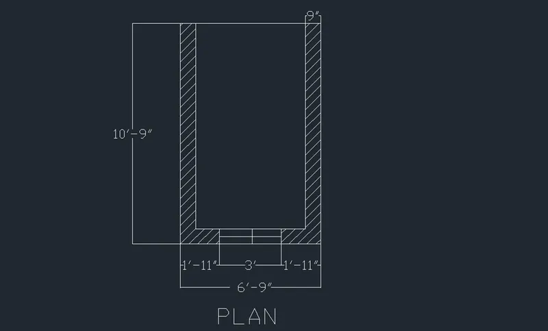
Creating plan:
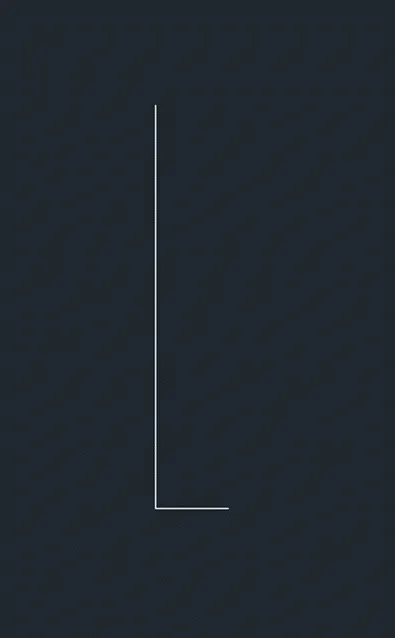
- Enter “LINE” command in the command box.
- Give first specify first point and
- Give next specify point as 10’9” in y -axis
- Give next specify point as 6’,9” in x -axis
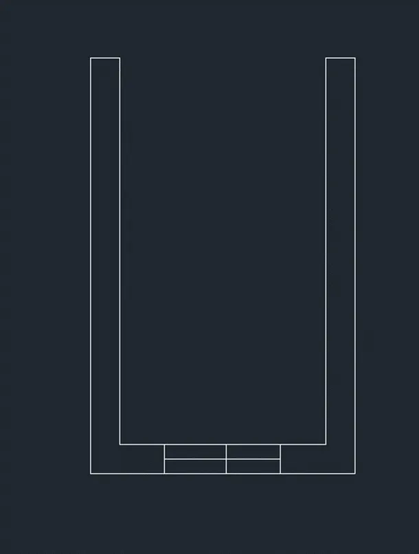
- Enter “OFFSET” command in the command box.
- Select the privies line and give offset value as 9” inside
- Enter “FILLET” command in the command box.
- Join the line as per the drawing
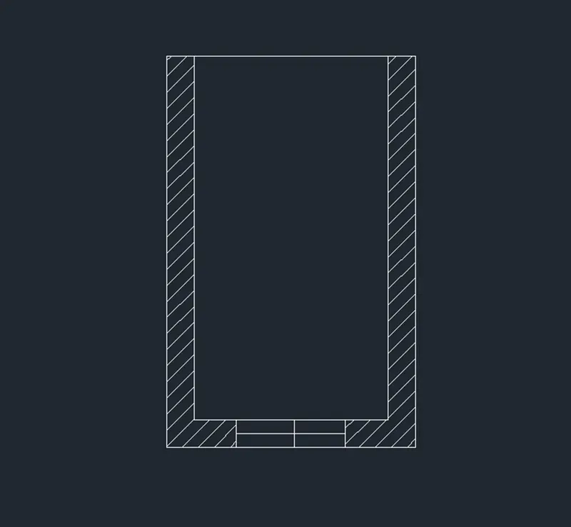
- Enter “HATCH “ command in the command box.
- Select the lines and give hatches as per the drawing .
- Enter “DIMLINER” command in the command box.
- Select the line and give show dimension as per the drawing .
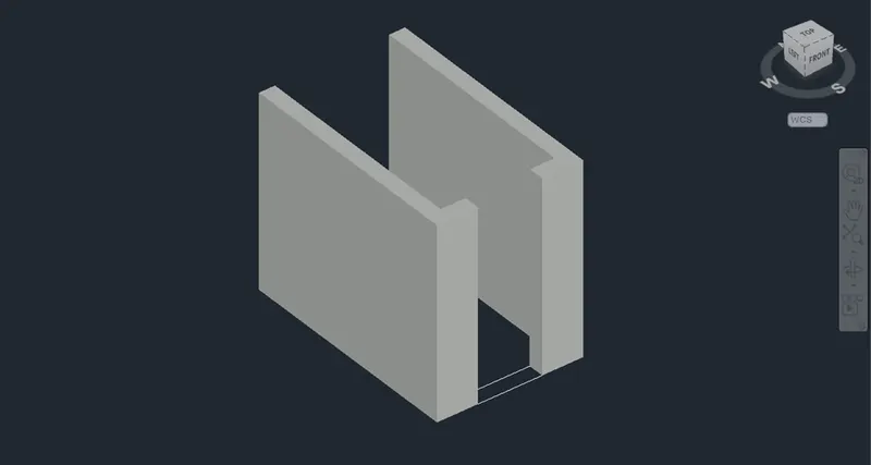
- Go to the UCS , change the views as south -west isometric
- Enter “JOIN” command in the command box.
- Select the object and join in the line.
- Enter “EXTRUDE” command in the command box.
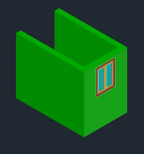
- Extrude the line as wall as per the drawing
- Go to the property and change the wall colour as “GREEN”
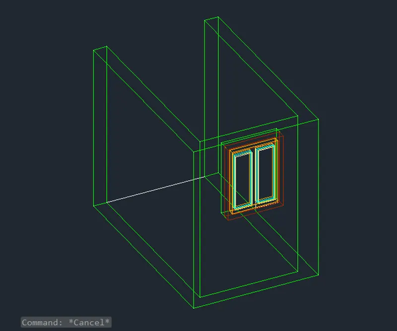
- Create a window in 2d
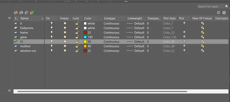
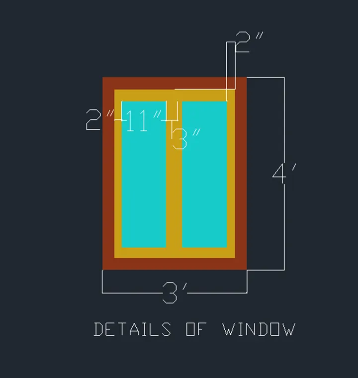
- Create a , GLASS, FRAME ,and MULLION in the layer option
- Enter “BOUNDRY” command in the command box.
- u will boundary creation as dialoge box ,
- set in region and click the pickup point, change the layer and set current
- select the “Frame” object and , click “ENTER”
- Enter “SUBTRACT” command in the command box.
- Select the large one and select the 2nd one
- Enter “BOUNDRY” command in the command box.
- u will boundary creation as dialoge box ,
- set in region and click the pickup point, change the layer and set current
- select the “ Mullion” object and , click “ENTER”
- Enter “SUBTRACT” command in the command box.
- Select the large one and select the 2nd one
- Enter “EXTRUDE” command in the command box.
- Extrude the window in the frame as 4” and mullion as 3”, glass as 5”
- Enter “MOVE” command in the command box.
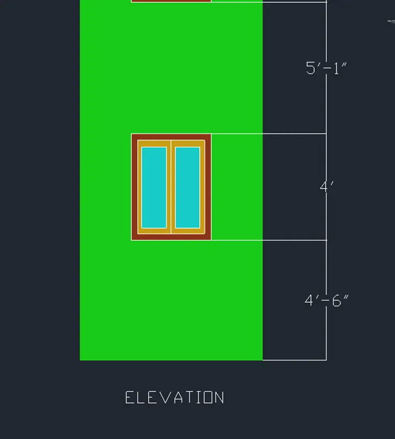
- Select the window and move window fix in the wall as per the drawing.
- Enter “DIMLINER” command in the command box.
- Show the dimension as per the drawing
- Change the “USC” show the view as per the drawing.
- Enter “UNION” command in the command box.
- Select the wall and , click “ENTER”
- Enter “COPY” command in the command box.
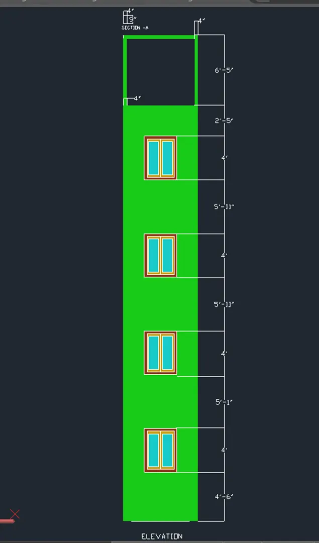
- Select the building drawing and past it above the drawing .
- Same like that create a building ,
- Finally show the result as per the drawing .
RESULT :
AIM:
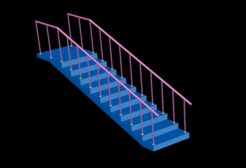
To Create the isometric 3d view of a stair with railing as shown in the plan and elevation.
Introduction :
Various command used while Sketching :
- Line command
- Units command
- Lim max command
- XL command
- Zoom command
- Text command
- Rectangle command
- Copy command
- Dimension command
- Layout command
- Limits command
- Boundary
- 3D Orbit
- 3D rotate
- Extrude command
- Region command
- UCS command
- UNION command .
- Camera command
- Block command
- Render RR command
- Sweep command
- Create light command
PRODUCTRE :
STEP 1 :
- GO to START MENU ,select AutoCAD 2018.
- Enter “UNITS” command in the command tab.
- Open “ Drawing units “ dialogue box , Type as “ENGINEERING ” and precision as 00
- Then click units scale to “INCHES ”
- Click “OK”.
- Enter “ LIM MAX” command in the command tab.
- Enter new value for Lim max as 200’.
- Enter “zoom” command in the command box.
- Enter “All” command in the command box.
- Enter “LIMITS” command in the command box.
- Specify lower left corner as “0,0”
- Specify right corner as 200’ , 200’
- Enter “zoom “ command in the command box.
- Enter “ALL” command in the command box.
STEP 2:
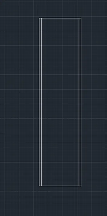
Creating plan for stairs:
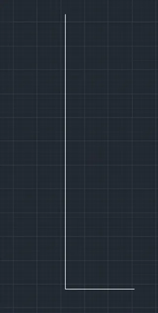
- Enter “LINE” command in the command box.
- Give first specify first point and
- Give next specify point as 3’ in y -axis
- Give next specify point as 12 ‘in x -axis
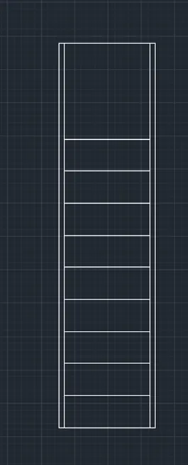
- Enter “OFFSET” command in the command box.
- Select the privies line and give offset value as 9” inside
- Enter “FILLET” command in the command box.
- Join the line as per the drawing
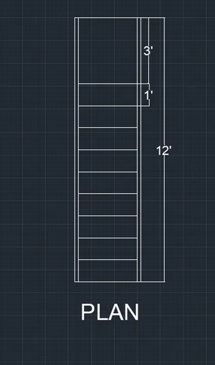
- Enter “DIMLINER” command in the command box.
- Select the line and give show dimension as per the drawing
- Go to the view , change the view as south -west isometric view
- Create a stairs riser as 6” and trad as 1’
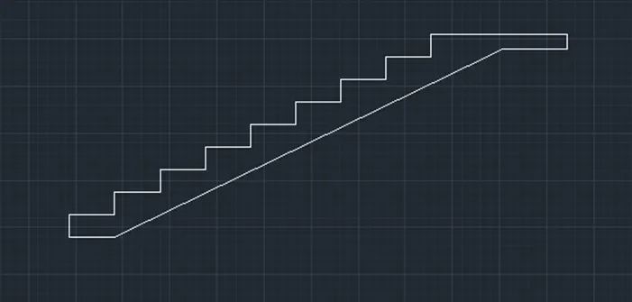
- Enter “EXTRUDE “ command in the command box.
- Extrude the stairs as 3’
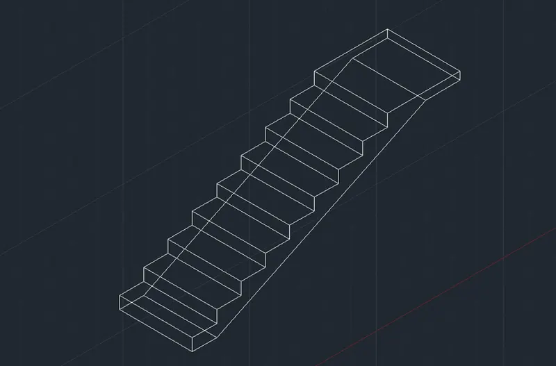
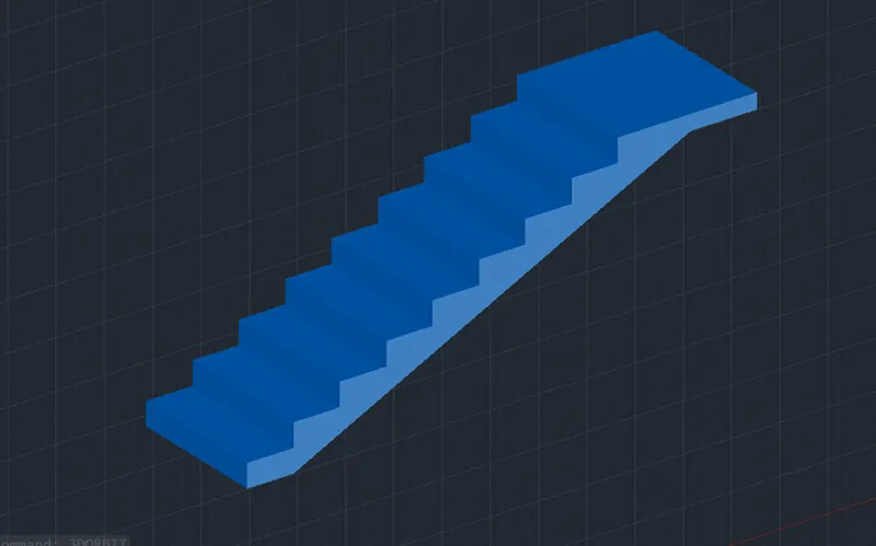
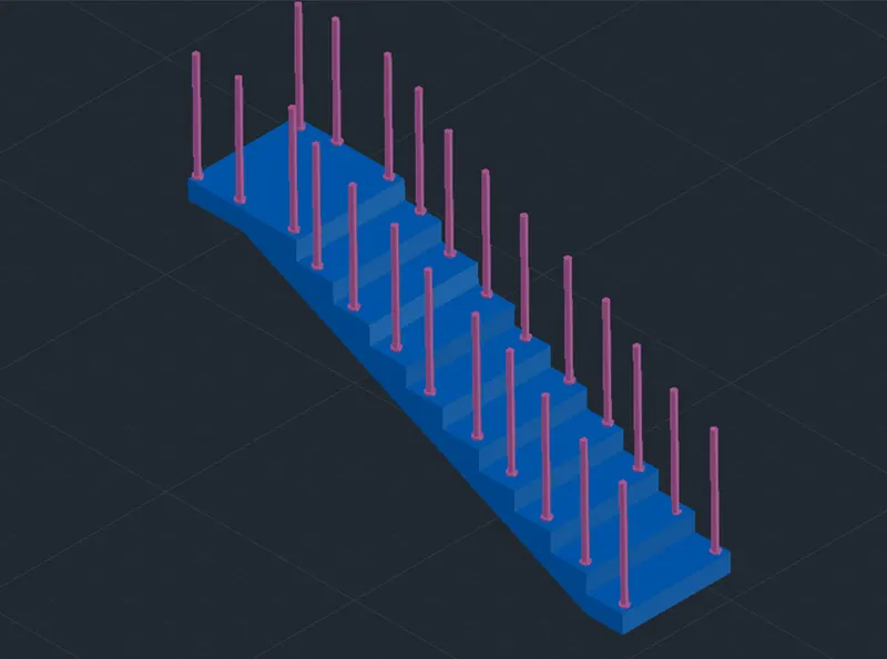
- Go to view – change the view as North -West Isometric
- Enter “UCS” command in the command box.
- Select the view , click “ENTER”
- Enter “CIRCLE” command in the command box.
- Create circles above the steps
- Enter “EXTRUDE” command in the command box.
- Extrude the circle height as 3’
- Go to the property and changes colour
- Finally show the result as per the drawing .
RESULT:
AIM:
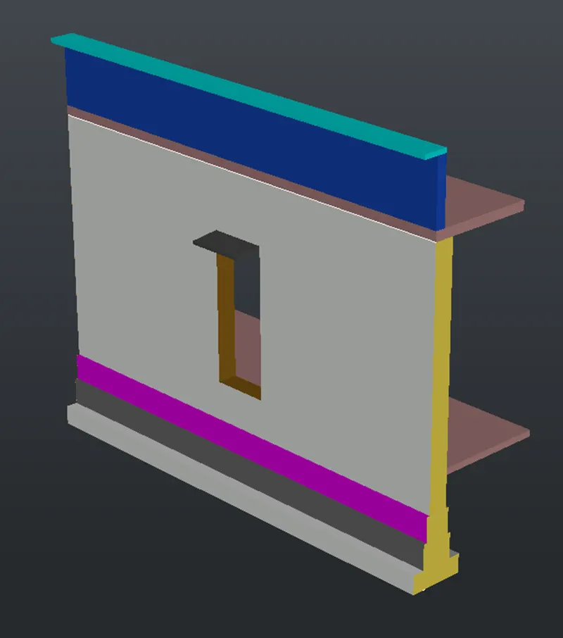
To Create the 3D view of a Wall with spread footing .
Introduction :
Various command used while Sketching :
- Line command
- Units command
- Lim max command
- XL command
- Zoom command
- Text command
- Rectangle command
- Copy command
- Dimension command
- Layout command
- Limits command
- Boundary
- 3D Orbit
- 3D rotate
- Extrude command
- Region command
- UCS command
- UNION command .
- Camera command
- Block command
- Render RR command
- Sweep command
- Create light command
PRODUCTRE :
STEP 1 :
- GO to START MENU ,select AutoCAD 2018.
- Enter “UNITS” command in the command tab.
- Open “ Drawing units “ dialogue box , Type as “DECIMAL ” and precision as 00
- Then click units scale to “MILLIMETTERS ”
- Click “OK”.
- Enter “ LIM MAX” command in the command tab.
- Enter new value for Lim max as 20000’.
- Enter “zoom” command in the command box.
- Enter “All” command in the command box.
- Enter “LIMITS” command in the command box.
- Specify lower left corner as “0,0”
- Specify right corner as 20000 , 20000
- Enter “zoom “ command in the command box.
- Enter “ALL” command in the command box.
STEP 2:
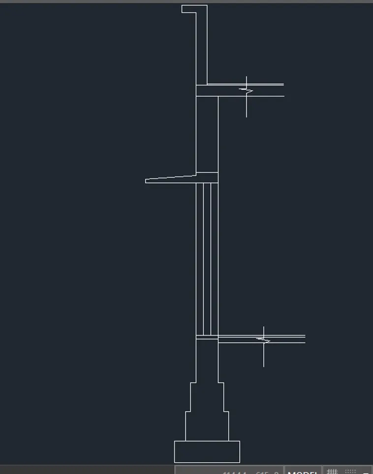
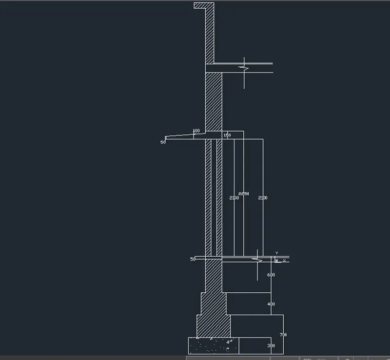
Creating Section of wall footing :
- Go to view , change the view as south -west isometric
- Enter “LINE” command in the command box.
- Give first specify first point and
- Give next specify point as 200mm
- From three give a specify point next value is 1000mm
- Enter “LINE” command in the command box.
- I given thickness as 150 mm for of the wall as per the drawing

- Enter “LINE” command in the command box.
- I given hight as 1000mm approximately
- Enter “LINE” command in the command box.
- Create line horizontally form the previous line
- Enter “OFFSET” command in the command box.
- Give a value 150mm from downside .
- Enter “LINE” command in the command box.
- Give a specify value as 3300mm from downside
- Enter “LINE” command in the command box.
- Give thickness of the wall as 300 mm
- Create like wall as per the drawing
- Enter “OFFSET” command in the command box.
- Give a offset value as “2100mm” from the upper side
- Enter “OFFSET” command in the command box.
- Give a offset value as “150mm” from the previse line
- Enter “LINE” command in the command box.
- Give a value of 50mm from downside line
- Enter “FILLET “ command in the command box.
- Filet the all the line as per the drawing
- Enter “LINE” command in the command box.
- Give height as 600mm, 400mm, 400mm and 300mm , in down side as per the drawing
- Create footing as per the drawing
- Enter “HATCH” command in the command
- Give a hatches as per the drawing
- Enter “DIMLINER “ command in the command
- Show the dimension as per the drawing
- Go to view command change view as south -west isometric
- Enter “JOIN “ command in the command box.
- Select the joining objects and click “ENTER”.
- Enter “EXTRUDE” command in the command box.
- Extrude the drawing length of 7500mm
- Enter “LINE” command in the command box .
- Create door as per the drawing
- Enter “subtract” command in the command box.
- Select the wall first , click “ENTER”
- Second select the door and click “ENTER”
- Door will be subtract from the wall as the drawing
- Give a colours and finally show the results.
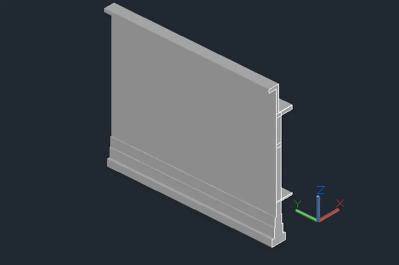
REUSLT:
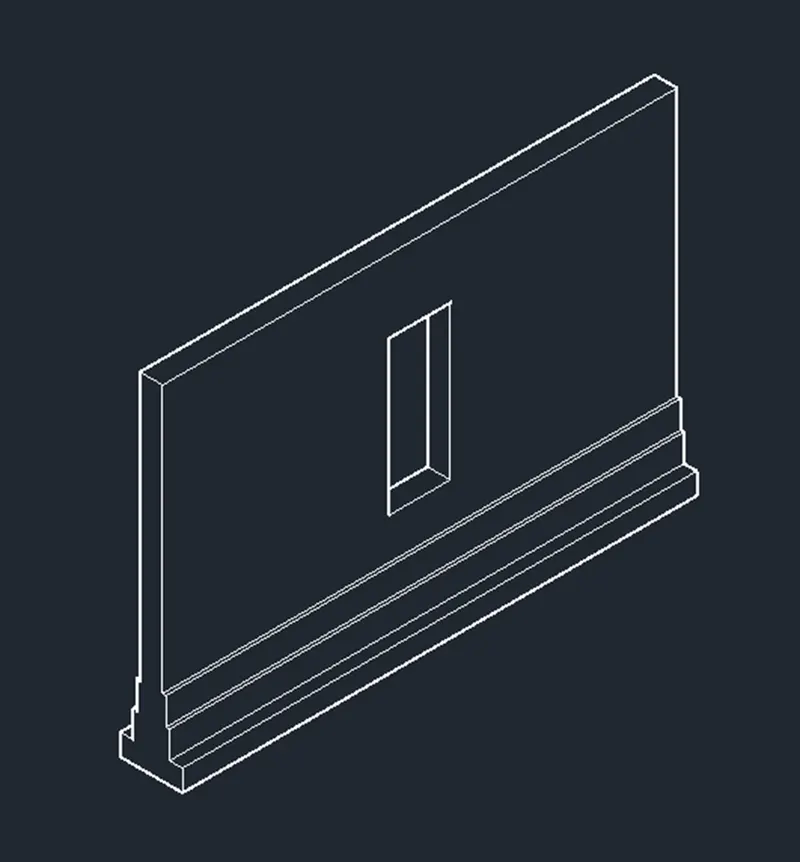
NOTE:
NOTE:
I’m working professional , that’s it’s take more time to submit the challenges , kindly accept my request , help me to improve my career and knowledge
Thank you.