Creating 3D Isometric view of various structural elements in AutoCAD
1)AIM
To create a 3D isometric view of plan and elevation using autocad.
INTRODUCTION
This 3D isometric view of plan and elevation is created using autocad and the procedure is explained in detail in each steps and the commands are used in this drawing are.
COMMANDS USED IN THIS DRAWING
- L- LINE
- F8- ORTHO MODE
- GRIDMODE
- F10 - POLAR TRACKING
- C- CIRCLE
- CO-COPY
- M-MOVE
- O-OFFSET
- F- FILLET
- D-DIMENSION STYLE
- REC-RECTANGLE
- 3F- 3Dface
- surftab1
- surftab2
- revsurf
- box
- cylindrical
- 3DO-3Dorbit
- 3DRotate
- 3Dface
- ucs
- v-view
- Box
- Cylinder
- Extrude
- Reg-region
- Union
- 3Dpoly
- SU-Subtract
- RR-render
PROCEDURE
STEP 1
- open autocad file in windows desktop.
- a dialog box will open it shows startup from scratch.
- click the radio button imperial to start the project.
- in command box type gridmode to show the gridmode by typing 1 in the command box
- type F8 to get ortho on.
- type limmax to set the maximum layout.
- type llmits to set the layout.
- press view cube icon to change the view to isometric xyz plane
- type L- LINE command in the command box.
- TYPE UN FOR UNITS and set to Feet and inches.
STEP 2
- press the top right corner to open the 3D Modeling (OR) press the bottom corner of workspace switching.
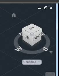
- then the UCS icon shows top of the workspace.
- use the top view to draw the 2d plan.
- then use the region option to region the plan as per dimension.
- type EX-Extrude the plan as per dimension.
- type Su-Subtract the window path and draw the window in the 3D.
- draw the window plan in the 2d and select the object to region.
- and extrude the window as per dimension.
STEP-3
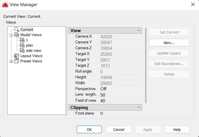
type v-view the object set the view in the current as shown below.
STEP-4
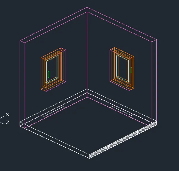
2D WIREFRAME MODEL
setting up 3d model to wireframe to see the accuracy of the model.
easy way to set up the window.
STEP-5
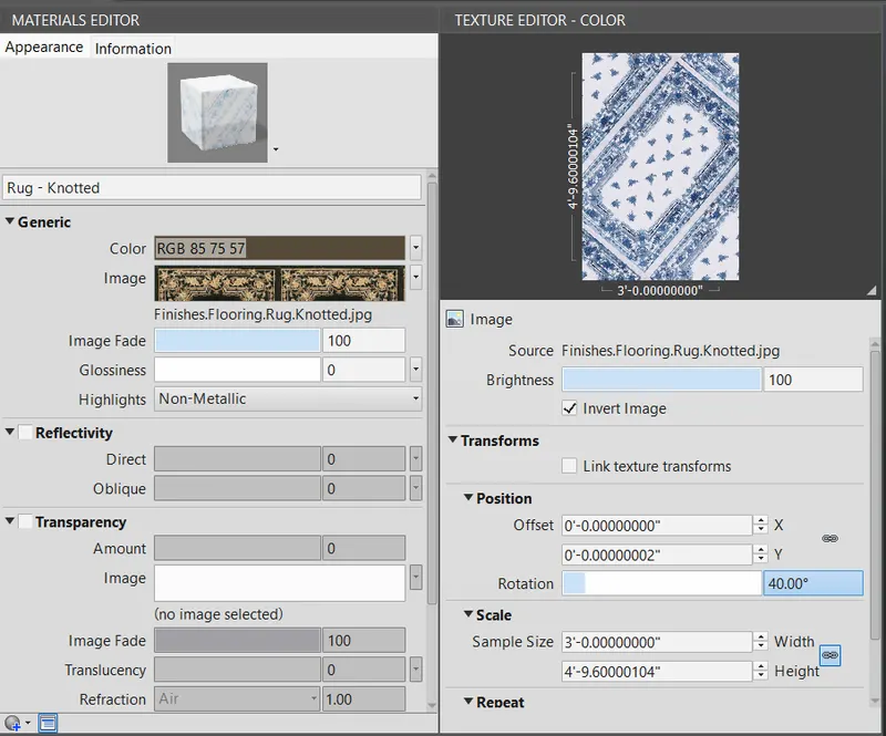
ADDING OF MATERIALS
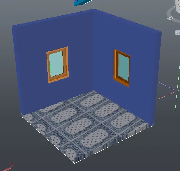
in the vizulaize ribbon the material manager are used in the drawing.
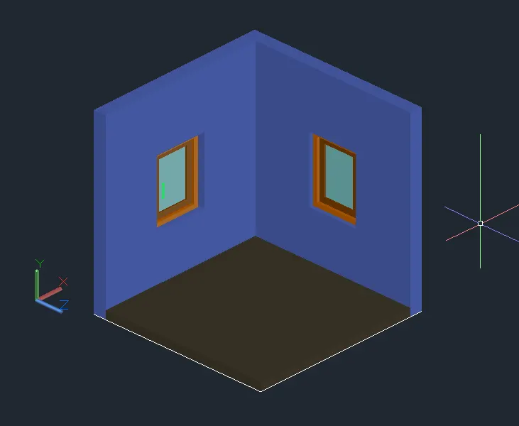
after setting up the material the image show below in the realistic model.
SHADED VIEW
REALISTIC VIEW
STEP-5
type RR- render option to render the object as per the resolution.
the image shows below.
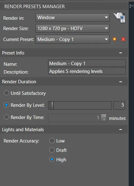
After rendering of object as per needs to lighting used and intensity

RESULT: The following isometric view of building with plan and elevation is completed.
2)AIM
To create a 3D view of building facade as given in the plan and elevation using autocad.
INTRODUCTION
This 3D view of building facade is created using autocad and the procedure is explained in detail in each steps and the commands are used in this drawing are.
COMMANDS USED IN THIS DRAWING
- L- LINE
- F8- ORTHO MODE
- GRIDMODE
- F10 - POLAR TRACKING
- C- CIRCLE
- CO-COPY
- M-MOVE
- O-OFFSET
- F- FILLET
- D-DIMENSION STYLE
- REC-RECTANGLE
- 3F- 3Dface
- surftab1
- surftab2
- revsurf
- box
- cylindrical
- 3DO-3Dorbit
- 3DRotate
- 3Dface
- ucs
- v-view
- Box
- Cylinder
- Extrude
- Reg-region
- Union
- 3Dpoly
- SU-Subtract
- V-Veiw
- Shaded
- Group
- RR-render
PROCEDURE
STEP 1
- open autocad file in windows desktop.
- a dialog box will open it shows startup from scratch.
- click the radio button imperial to start the project.
- in command box type gridmode to show the gridmode by typing 1 in the command box
- type F8 to get ortho on.
- type limmax to set the maximum layout.
- type llmits to set the layout.
- press view cube icon to change the view to isometric xyz plane
- type L- LINE command in the command box.
- TYPE UN FOR UNITS and set to Feet and inches.
STEP 2
- press the top right corner to open the 3D Modeling (OR) press the bottom corner of workspace switching.
- then the UCS icon shows top of the workspace.
- use the top view to draw the 2d plan.
- then use the region option to region the plan as per dimension.
- type EX-Extrude the plan as per dimension.
- type Su-Subtract the window path and draw the window in the 3D.
- draw the window plan in the 2d and select the object to region.
- and extrude the window as per dimension.
STEP-3
type v-view the object set the view in the current as shown below.
STEP-4
- Draw the 2d model of the plan and set the workplane ton 3d
- type REG-Region to extrude the plan as per the 2d plan in the top view
- extrude the two side of the wall builiding as per dimension.
STEP-5
- Draw the window drawing in 2d.
- group the object to set in one.
- rotate the object to 90 degree
- and region the object to one and extract the object to be needed.
- type su-subtract the object which is not needed.
- setv the thickness of the window as per the dimnesion.
STEP-6
copy the window as per the levels of the building.
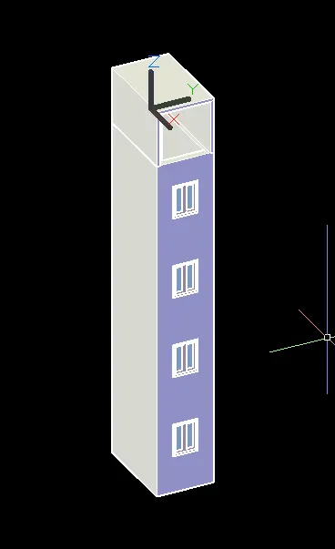
2D WIREFRAME MODEL
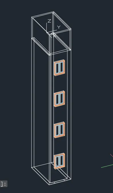
SHADED MODEL
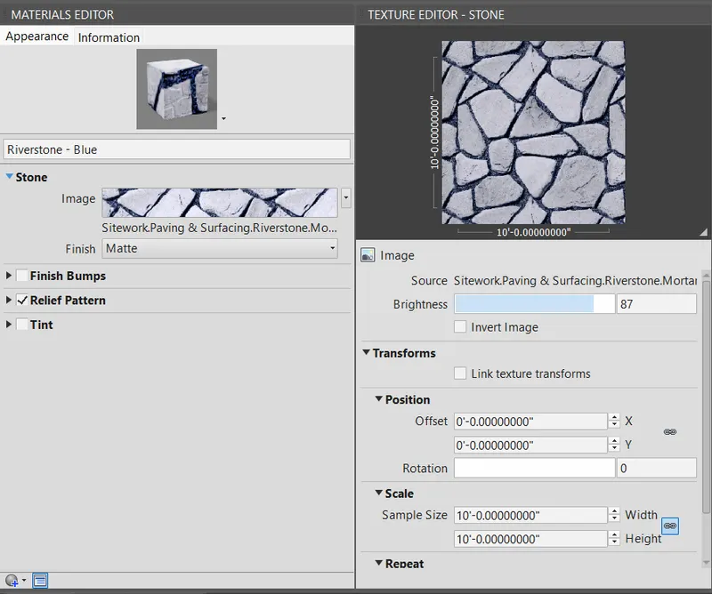
ADDING OF MATERIALS
in the vizulaize ribbon the material manager are used in the drawing.
after setting up the material the image show below in the realistic model.
REALISTIC VIEW
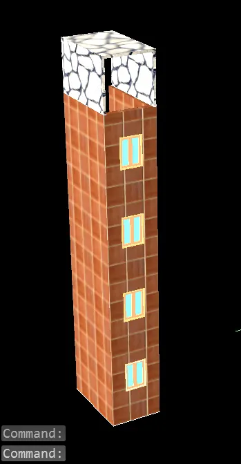
STEP-7
Type rr-render the building facade.
RESULT: the follwing 3d building facade as given in the plan and elevation is completed.
3)
AIM
To create a 3D view of stairs as given in the plan and elevation using autocad.
INTRODUCTION
This 3D view of stairs is created using autocad and the procedure is explained in detail in each steps and the commands are used in this drawing are.
COMMANDS USED IN THIS DRAWING
- L- LINE
- F8- ORTHO MODE
- GRIDMODE
- F10 - POLAR TRACKING
- C- CIRCLE
- CO-COPY
- M-MOVE
- O-OFFSET
- F- FILLET
- D-DIMENSION STYLE
- REC-RECTANGLE
- 3F- 3Dface
- surftab1
- surftab2
- revsurf
- box
- cylindrical
- 3DO-3Dorbit
- 3DRotate
- 3Dface
- ucs
- v-view
- Box
- Cylinder
- Extrude
- Reg-region
- Union
- 3Dpoly
- SU-Subtract
- RR-render
- V-Veiw
- Shaded
- Group
PROCEDURE
STEP 1
- open autocad file in windows desktop.
- a dialog box will open it shows startup from scratch.
- click the radio button imperial to start the project.
- in command box type gridmode to show the gridmode by typing 1 in the command box
- type F8 to get ortho on.
- type limmax to set the maximum layout.
- type llmits to set the layout.
- press view cube icon to change the view to isometric xyz plane
- type L- LINE command in the command box.
- TYPE UN FOR UNITS and set to Feet and inches.
STEP 2
- press the top right corner to open the 3D Modeling (OR) press the bottom corner of workspace switching.
- then the UCS icon shows top of the workspace.
- use the top view to draw the 2d plan.
STEP-2
- Draw the plan in the 2d plane.
- set the object into group.
- type 3dr- 3dRotate the object in the 90 degree.
- type reg-region the stairs in the alignment.
- and extrude the object to 3 ' as per dimension
STEP-3
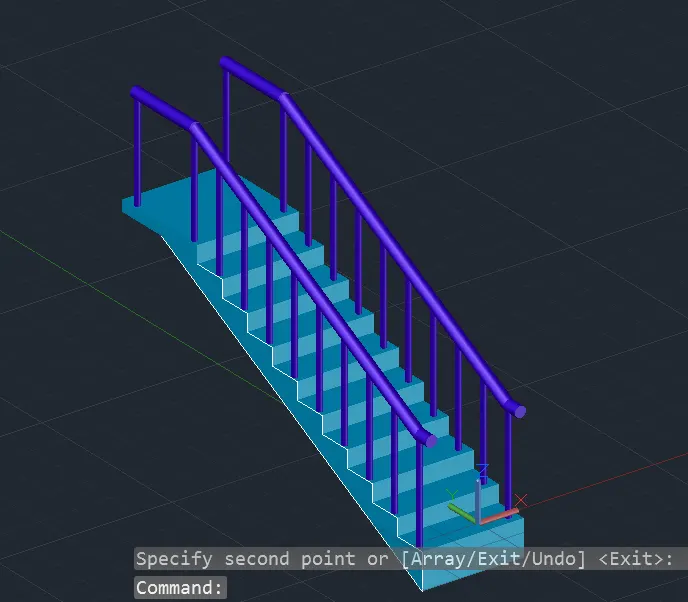
type v-view the object set the view in the current as shown below.
2D WIREFRAME
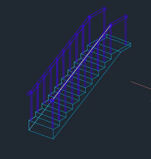
SHADED
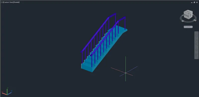
RESULT: The following 3D stair is done as per dimension is completed.
4)
AIM
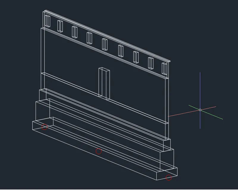
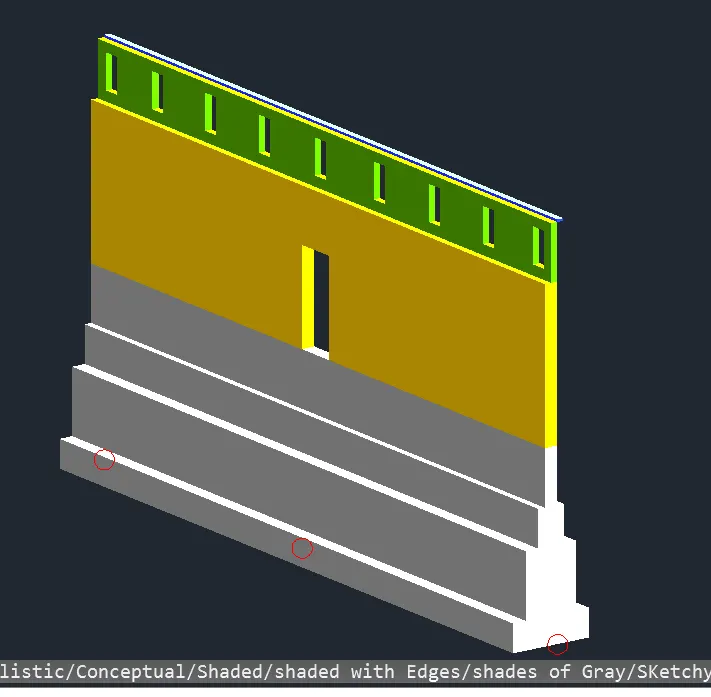
To create a 3D view of wall with spread footing given in the plan and elevation using autocad.
INTRODUCTION
This 3D view of wall with spread footing is created with using autocad and the procedure is explained in detail in each steps and the commands are used in this drawing are.
COMMANDS USED IN THIS DRAWING
- L- LINE
- F8- ORTHO MODE
- GRIDMODE
- F10 - POLAR TRACKING
- C- CIRCLE
- CO-COPY
- M-MOVE
- O-OFFSET
- F- FILLET
- D-DIMENSION STYLE
- REC-RECTANGLE
- 3F- 3Dface
- surftab1
- surftab2
- revsurf
- box
- cylindrical
- 3DO-3Dorbit
- 3DRotate
- 3Dface
- ucs
- v-view
- Box
- Cylinder
- Extrude
- Reg-region
- Union
- 3Dpoly
- SU-Subtract
- V-Veiw
- shaded
- RR-render
PROCEDURE
STEP 1
- open autocad file in windows desktop.
- a dialog box will open it shows startup from scratch.
- click the radio button imperial to start the project.
- in command box type gridmode to show the gridmode by typing 1 in the command box
- type F8 to get ortho on.
- type limmax to set the maximum layout.
- type llmits to set the layout.
- press view cube icon to change the view to isometric xyz plane
- type L- LINE command in the command box.
- TYPE UN FOR UNITS and set to MILLIMTERES
STEP 2
- press the top right corner to open the 3D Modeling (OR) press the bottom corner of workspace switching.
- then the UCS icon shows top of the workspace.
- use the top view to draw the 2d plan.
STEP-3
TYPE v-view to set the view in the 3d plane as shown in the fig below.
set the ucs as current as to edit in the plane.
STEP 4
2D WIREFRAME VIEW
SHADED VIEW
ADDING OF MATERIALS
in the vizulaize ribbon the material manager are used in the drawing.
after setting up the material the image show below in the realistic model.
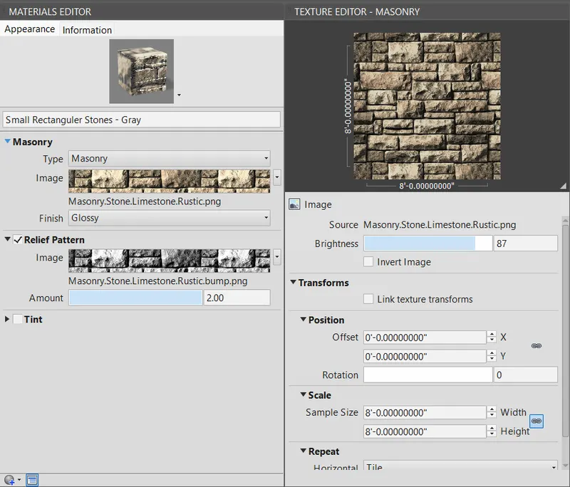
REALISTIC VIEW
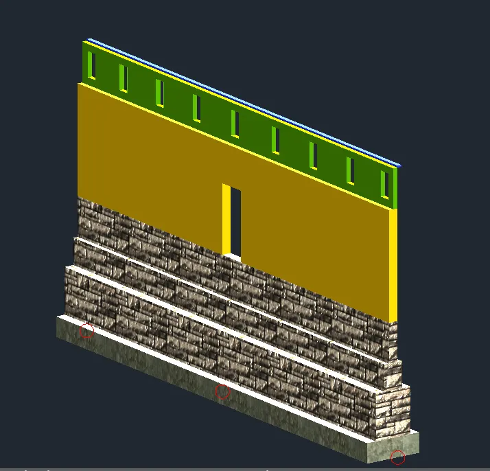
STEP-5
TYPE RR-render the tab option shown as shown in the fig below.
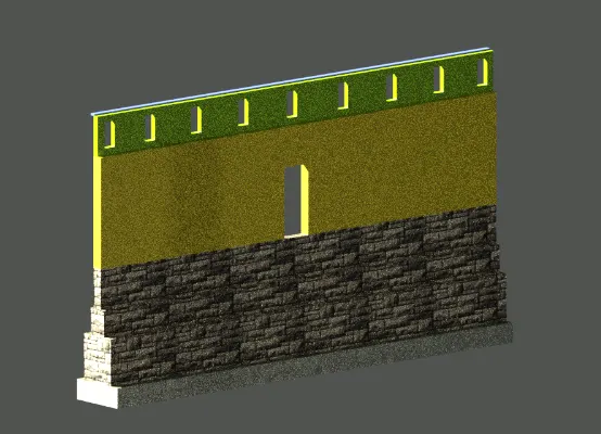
RESULT: the following 3d view of a wall with spread footing is completed.