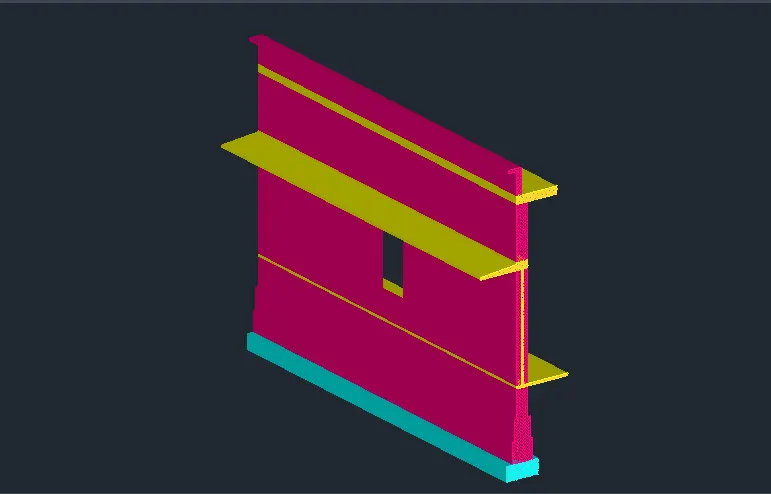
Creating 3D Isometric view of various structural elements in AutoCAD
Aim:
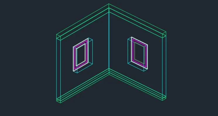
To create a 3D isometric view of the building with the given plan and elevation
Introduction:
Isometric drawing is a form of 3D drawing which is set of using 30 degree angles. It is a type of action matric drawing so that schemes scale is used for every access. Resulting in a non distorted image. Since isometric creed are pretty easy to set up once you understand the basic of isometric drawing and creating the free hand isometric sketch is relatively simple.
Command used :
- Units
- Limits
- Rectangle
- Line
- Offset
- Trim
- Boundary
- Region
- Extrude
- Copy
Procedure:
- Open the autocad software and click on need drawing and switch the model into 3D modelling from the status bar
- Type UN and set the units as engineering and precision as 0'0"
- Set the units as inches in the insertion scale
- Type limit in the command box and set lower limit as 0 and upper limit as 50',50'
- Type Z for zoom enter and A enter for zoom all
Step 1
- Go to the top view using UCS icon at the top right corner
- Select the rectangle tool and draw a rectangle of dimension 10'9" x 10'9"
- Select the upset too let give the outside as 9" and offset the rectangle through inside as showing figure
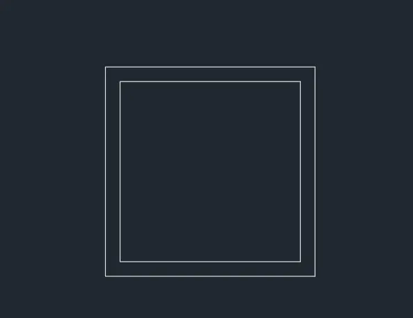
Step 2:
- Select the trim tool and trim the unnecessary lines
- Cream the right side line so it would looks like L shape wall
- Using the land command join the line at the corner
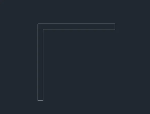
Step 3:
- Select the offset tool and give the outside distance as 1'6"
- Draw the line at the middle of the wall and offset it through the both sides
- Using the line quant draw the line in the middle as shown in the window location
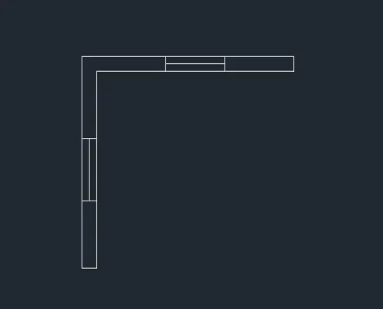
Step 4:
- Go to the default 3D view using UCS icon in the top right corner
- Select the boundary tool by typing boundary in the command box and pick the boundary point as inside of the wall and press okay
- Select the reason tool by typing REG in the command box and select the wall except the window and press okay to make the region
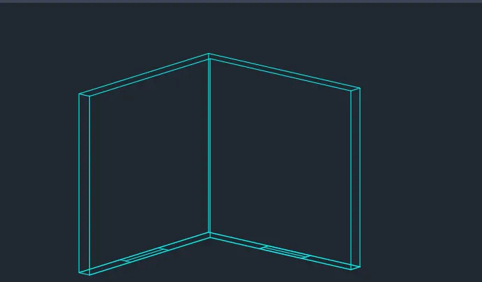
Step 5:
- Select the extrude command in command box
- Extrude the reason with height of 10' into the Z axis
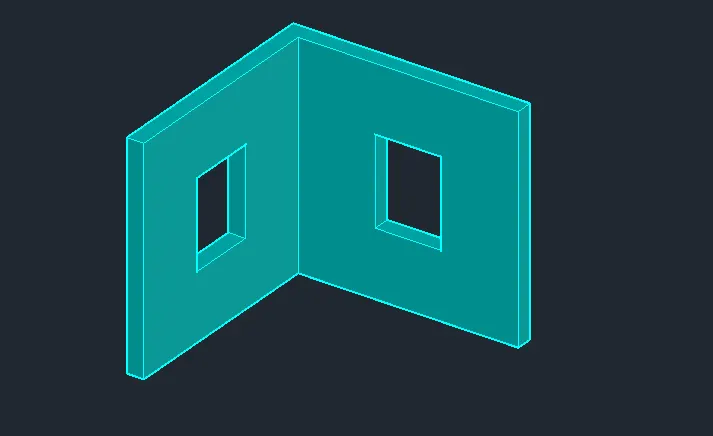
Step 6:
- Select the rectangle tool and row a rectangle over the window portion
- Select the extrude tool and extrude it to the top with the height of 3' to still level
- Similarly create another rectangle at the top
- Extraordinates through the below level with the height of 3' from the top
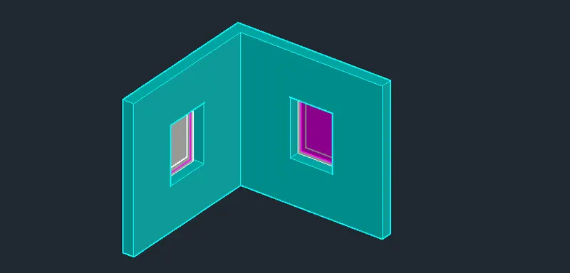
Step 7:
- Select the rectangle tool and raw of dimension 3'X3'
- Select the boundary tool by typing BO
- Pick the reason and create the boundary for the frame million and grass as shown in the figure
- Select the X2 tool and extrud it into 3' for the frame and to 1.2" for million and 0.6" the glass
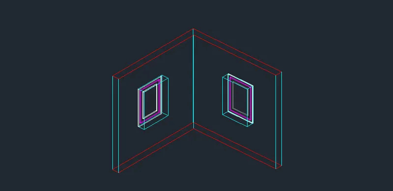
Step 8:
- Select copy tool and copy the window to the desired location
Aim:
To create 3D view of the building facade with detail of the window as per the given plan and section
Introduction:
Building facade refers to one side normally the front side of the building structure. It is one of the most Italy peace to overall design the structure as it at unique personality and connected to it. Building packet can be saffron shapes and sizes it is one of those pieces in the structure that provides architect with the change to experiment and show case their talent and bring their certains to life .
Command used :
- Units
- Limits
- Rectangle
- Line
- Offset
- Trim
- Boundary
- Region
- Extrude
- Copy
Procedure:
- Open the autocad software and click on need drawing and switch the model into 3D modelling from the status bar
- Type UN and set the units as engineering and precision as 0'0"
- Set the units as inches in the insertion scale
- Type limit in the command box and set lower limit as 0 and upper limit as 50',50'
- Type Z for zoom enter and A enter for zoom all
Step 1:
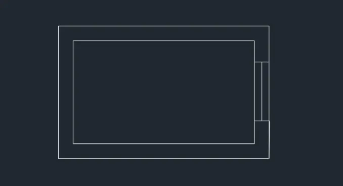
- Select the rectangle tool by typing rectangle and daw a rectangle of dimension 10'9"and 6'9"
- Let me also to land rover the offset distance of 9"
- Offset the previous rectangle through inside as shown in the figure
- Select the line tool and create the window on the right side of the wall has shown in figure
Step 2:
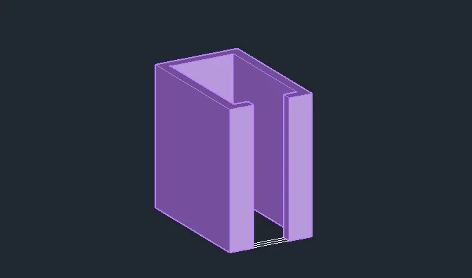
- Select the boundary tool and pick the point inside and create the boundary section of the rectangle
- Slug the reason tool and select the rectangle and press okay to create the region
Step 3:
- Select the extrude tool by typing EXT in the command box
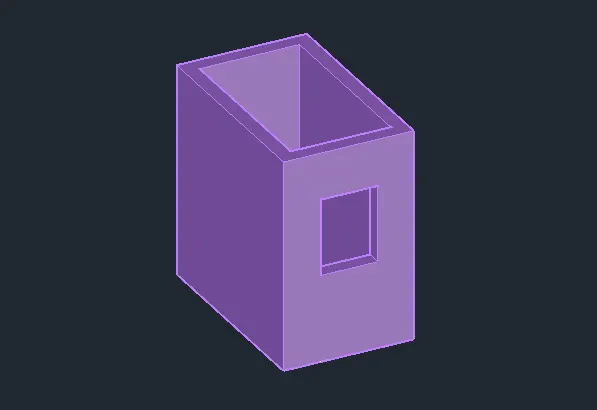
- Extrude the rectangle with the height of 10'11" at the top
- Total height of the wall is 10'11" and sill height 4'6" and window height is 4'
Step 4:
- Select the tanker tool and draw the rectangle below at window position
- Select the extrude tool and extrude it to the top with the height of 4'6"
- Similarly create another rectangle at the top of the window portion
- Select extrud tool and extrude below with the height of 2'5"
Step 5:
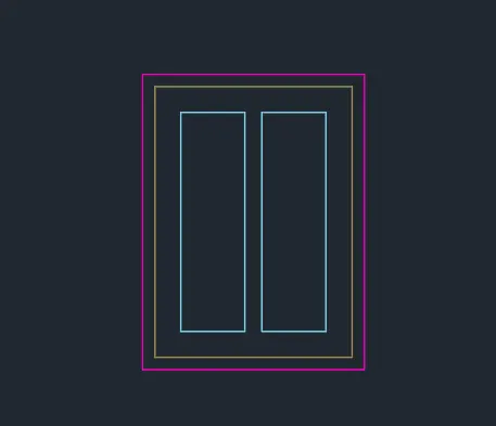
- Select the rectangle tool andro the window of dimension 4'x 3' in the top view
- Draw the window as per the required dimensions
- Select the extrude tool and extrude 3" for the frame 1.6" million and 1" for the glass
- Using layer tool provide appropriate layer as shown in the figure
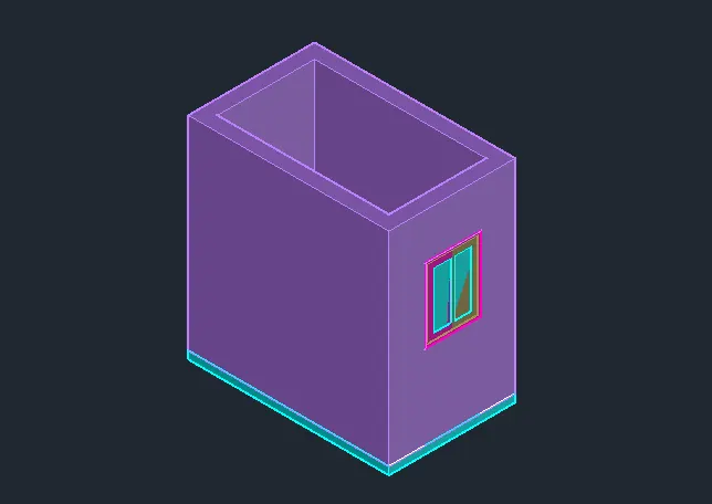
- Select the move tool and move the window to the desire location
- Snapdeal tangle tool and create the rectangle itself from the roof
- Select the extrude tool and extrude that angle by 5" at the bottom
Step 6:
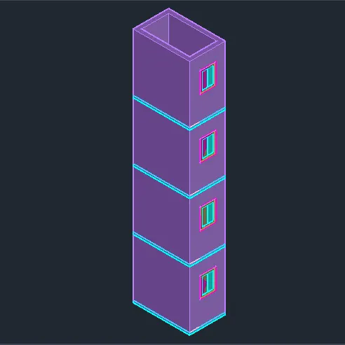
- Select the copy tool and copy the first floor and move it to decide location for the four times
Step 7:
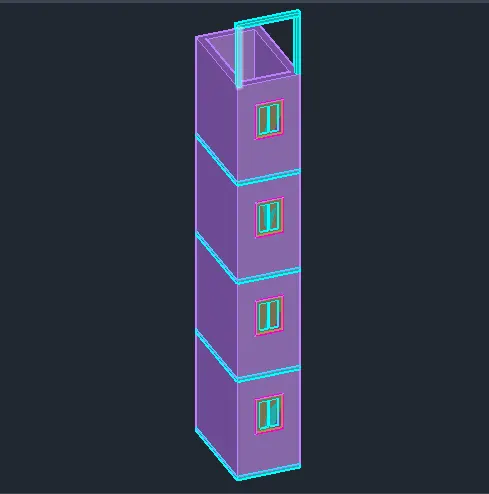
- Select the UCS tool by typing UCS in the command box
- Placed UCS on the top surface of the building
- Draw the rectangle with the dimension of 9"x4 "at the top level
- Select the extrude tool andExtrude rectangle by 4"
Aim:
To create the isometric view of the stair by railing as per the given plan
Introduction:
A stair is a step leading from one floor to the another building typically inside the building. The room over and closed of the building in which this year are located is known as a staircase. The opening or the space occupied by the stair is known as stairway full stop type of stairs used in buildings are broadly based on the shape of the stairs. Straight stairs turning stairs and continue stairs are broad type of stairs
Command used :
- Units
- Limits
- UCS
- Line
- Offset
- Trim
- Boundary
- Region
- Extrude
- Copy
- Circle
- 3DPoly
- Mirror
- Sweep
Procedure:
- Open the autocad software and click on need drawing and switch the model into 3D modelling from the status bar
- Type UN and set the units as engineering and precision as 0'0"
- Set the units as inches in the insertion scale
- Type limit in the command box and set lower limit as 0 and upper limit as 50',50'
- Type Z for zoom enter and A enter for zoom all
Step 1:
- Select the UCS icon at the top right corner and go for the front view
- Select line command and draw line with the rise of 6" and thread as 1'
- Select the copy tool and copy the thread and rise into the different level shown in figure
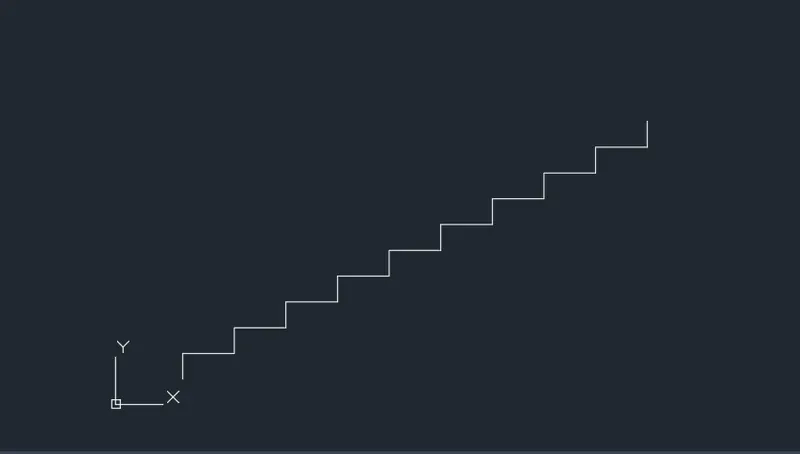
Step 2:
- Select the line to again and draw the line of length 3' for thewave slab dl
- Draw another line below the thickness of 4" for the wave slab
- Connect the slab and below thread to the to form a section of the stair
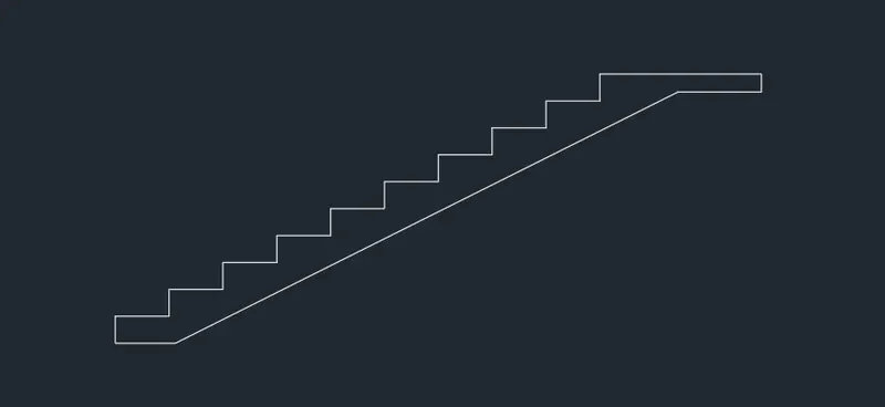
Step 3:
- Go to the default 3D view by using UCS icon
- Select the bounted tool and create a reason inside the section
- Select extrude tool and extrude section to the left side with an extrude height of 3"
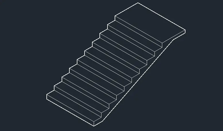
Step 4:
- Select the ucs tool by typing uses in the command box
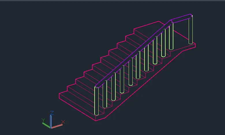
- Place the uses icon on the thread to create the hand rails
- Select the tool and create the circle with the radius of 2" on the thread
- Select the extrud and extrude the circle with the height of 3"
- Select the copy tool and copy the circle and Move it to the another thread as shown in figure below
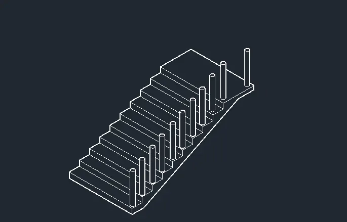
Step 5:
- Select the 3D polyn by typing 3p in the command box
- Draw the polynine starting at the point of the first circular column at the last colum
- Draw the another circle with the radius of 2"
- Select the swipe tool and select the circle to sleep it into the polyline
Step 6:
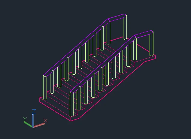
- Select the mirror tool by typing mirror in the command box
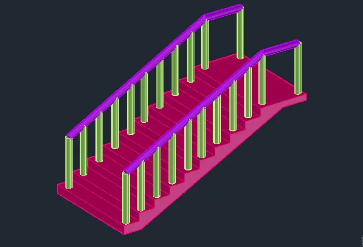
- Select the balustrades and handrails and mirror them through the other side as shown in figure
RESULT:
Aim:
To create the 3D view of the wall with spread fooding as per the given plan and education details
Introduction:
The spread folding is utilise to sport the column and wall and additionally to convey and desinate
And local coming to the structure to the soil below 8. This type of fooding maybe a circular, square and rectangle slab of the uniform thickness and to spread the load over the size able areas sometimes it stepped. The base of the spread fooding is slightly wider than the load bearing foundation base. This is also called step spread foundation
Command used :
- Units
- Limits
- Line
- Offset
- Extend
- Boundary
- Circle
- Hatch
Procedure:
- Open the autocad software and click on need drawing and switch the model into 3D modelling from the status bar
- Type UN and set the units as decimal and precision as 0
- Set the units as millimetres in the insertion scale
- Type limit in the command box and set lower limit as 0 and upper limit as 10000,10000
- Type Z for zoom enter and A enter for zoom all
Step 1:
- Go to the top view using the ucs icon at the top right corner
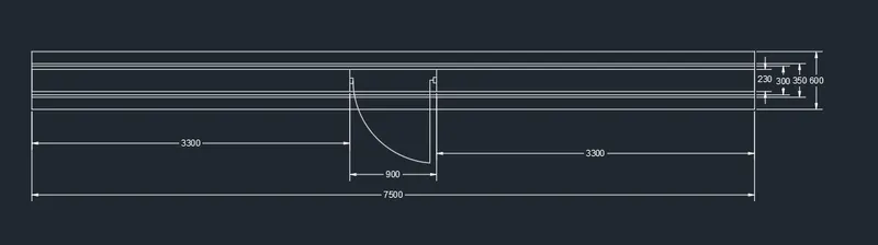
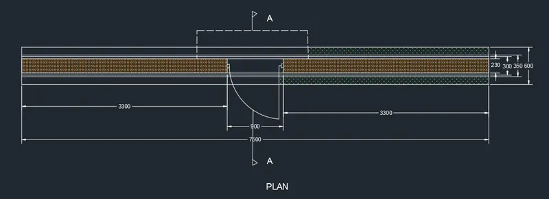
- Select the line tool and draw the line vertical of length 750 mm and 230 mm in with
- Draw centre line in the wall and offset 150 mm on both sides
- Select the offset too Lage and give the outside distance at 25 mm
- Select the 300 mm line and offset it through outside
- From the centre line again give an offset distance of 300 mm and offset it through both sides
- By using extent command extend the horizontal line
- Select the offset tool again and give the option distance of 3300mm
- Select the horizontal line and offsets of the door opening of 900 mm
Step 2:
- By using circle tool and line tool create the door opening
- Select the hatch tool by typing hatch in the command box and select the hatch pattern as per the requirement
Step 3:
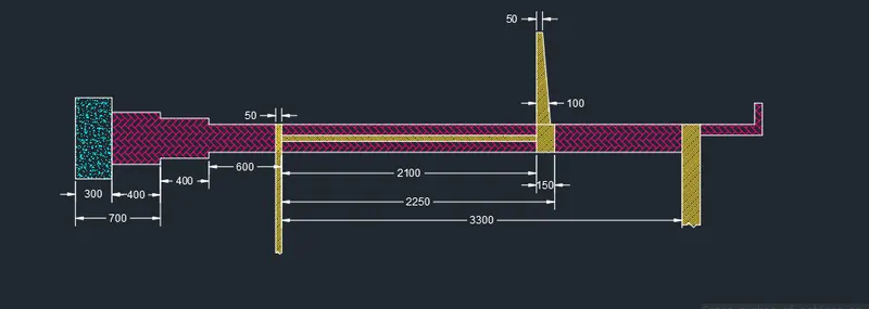
- Create the little by using line command and do the hatching
- At the top of the section use break line to represent the section
- Select the dim linear command and provide the necessary dimensions
Step 4:
- Go to the default 3D view using ucs icon at the top right corner
- Create a profile for the footing step in the 2D plan and copy it through the 3D plan with the help of snap tool
- Select the boundary tool and pic inside the fooding to create the region
- Select the extrude and extrud The reason by 400 mm
- Similarly do the same procedure for the remaining profile as shown in the figure below
- Now select the extrude tool and extrude the lintel for 75 00 mm
- Select the rectangle tool and row a rectangle of height 1050 mm and with 900 mm and make the door
- Select the boundary tool and big tea boundary of the door
- Select the subtract command and subtract the door from the wall as shown in figure