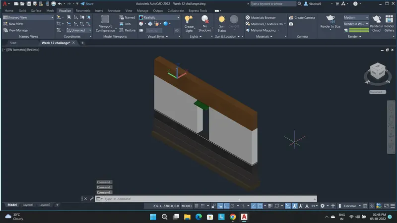
Creating 3D Isometric view of various structural elements in AutoCAD
Answer 1-
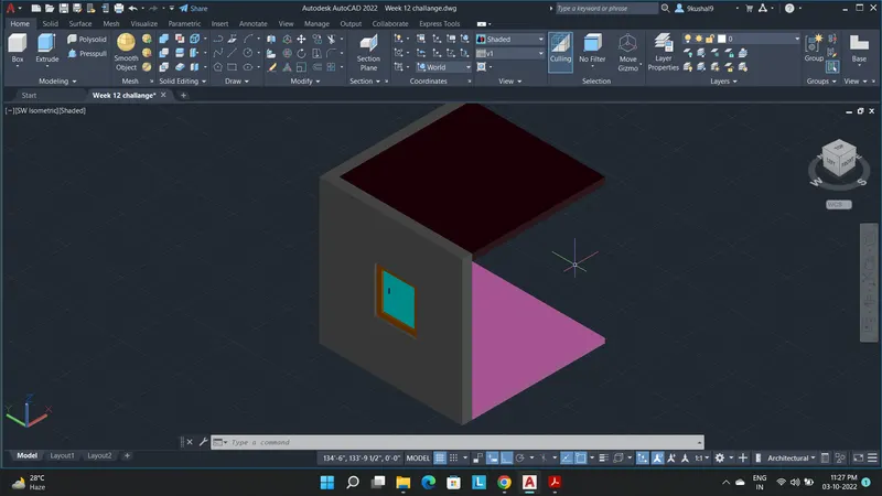
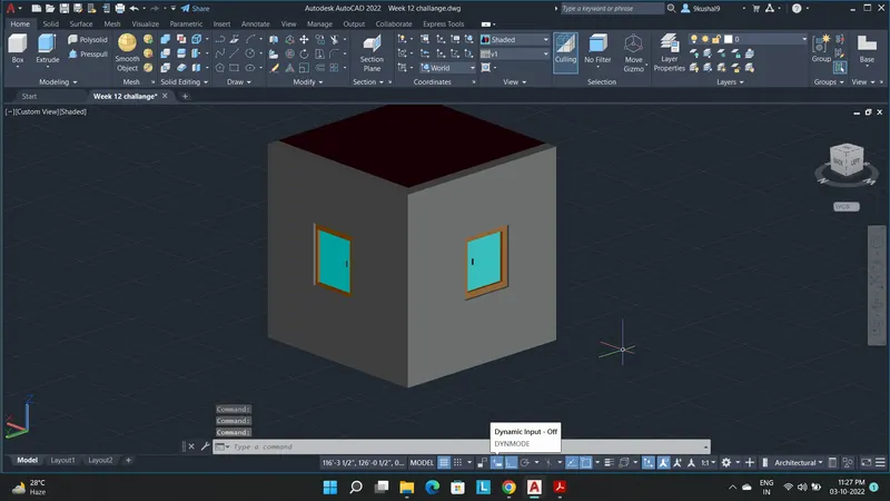
Aim- To create a 3D Isometric View of the building with plan and elevation given.
Step 1- Drawing a rectangular of size 10'9"x10'9"
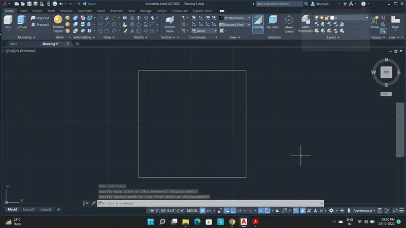
Step 2- Making offset of 9" and triming unwanted sides
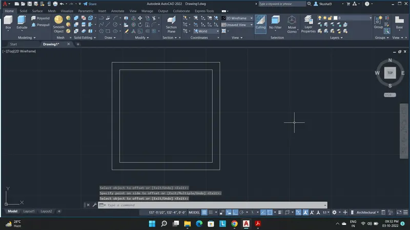
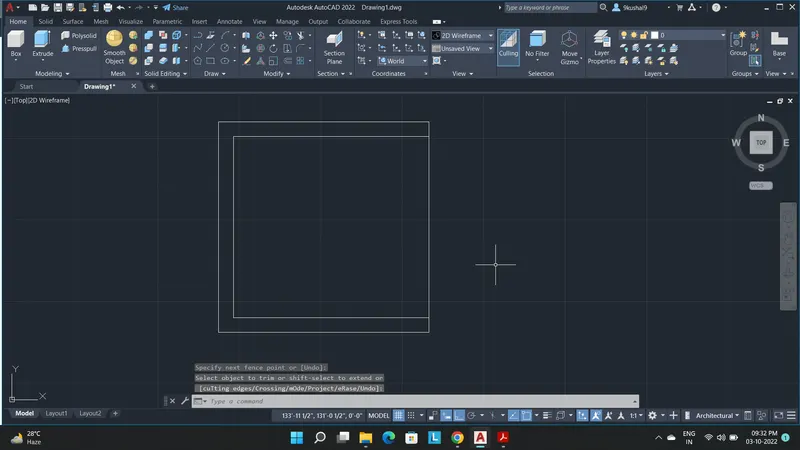
Step 3- Ploting the plan as per given drawing.
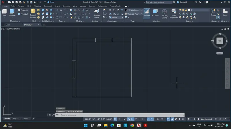
Step 4- Changing the view to 3D Isomatric view
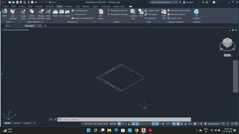
Step 5- Extruding wall, floor and slab
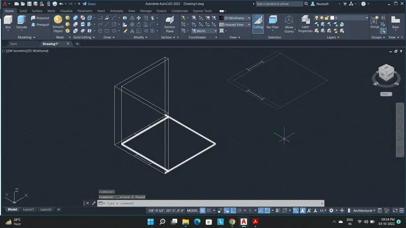
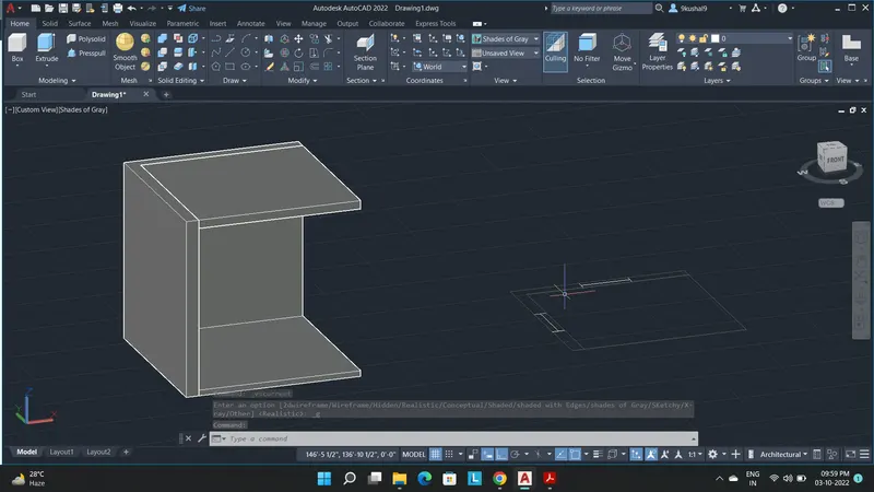
Step 6- Extruding and subtracting the window from the wall
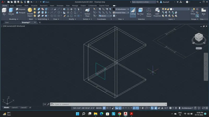
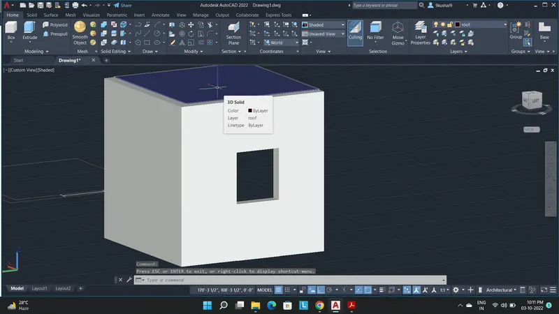
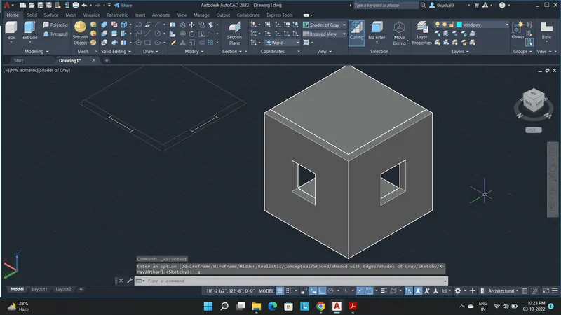
Step 7- Setting up layers for different items.
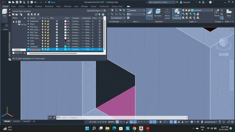
Step 8- Making window frame
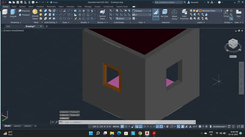
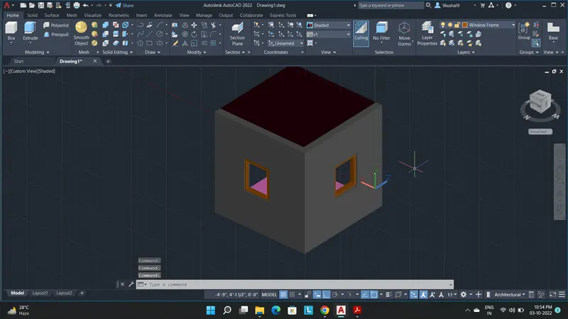
Step 9- Making window glass
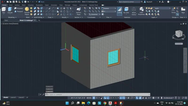
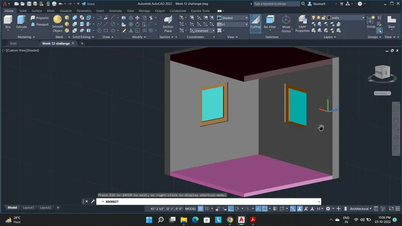
Final Result- below are the attached results in shaded view.
Answer 2-
Aim-
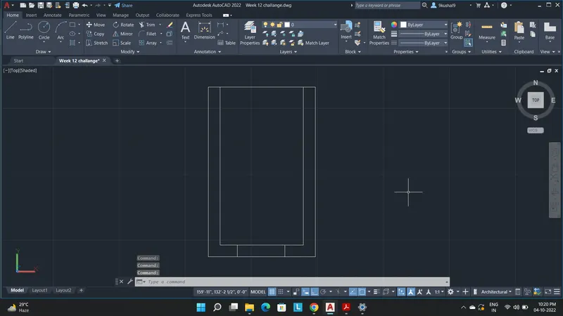
Step 1- drawing the plan as per given drawing
Step 2-
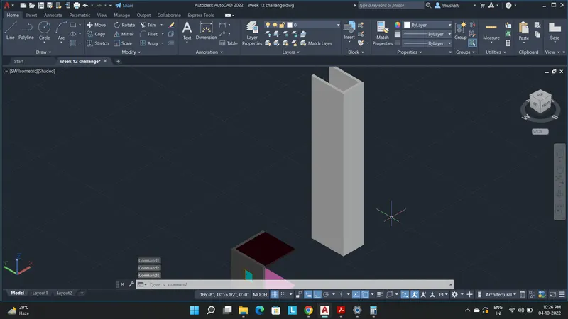
Step 3-
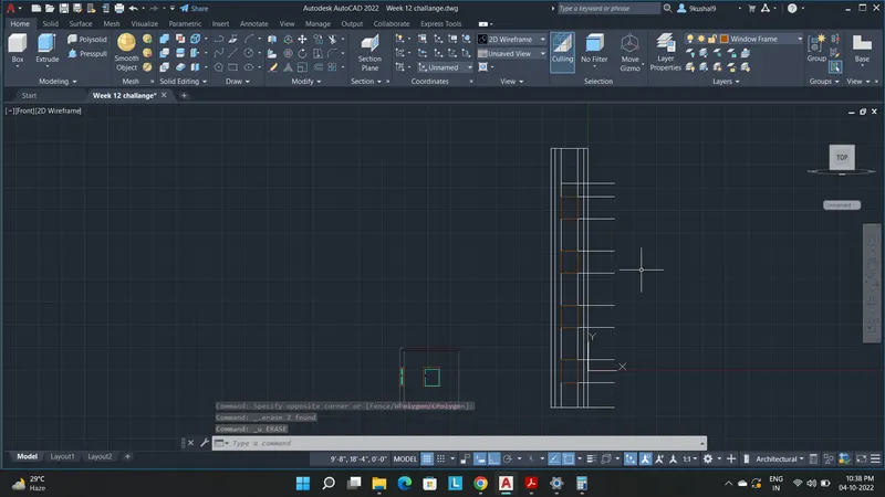
Step 4-
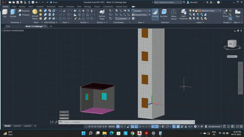
Step 5-
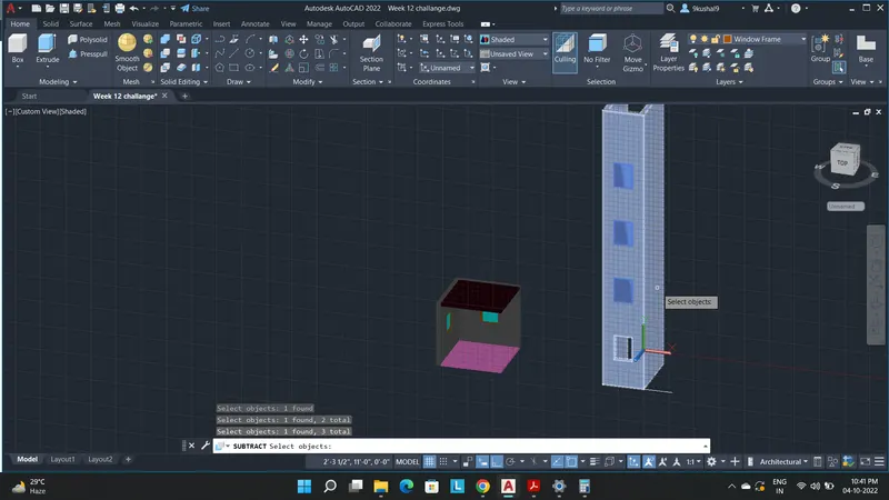
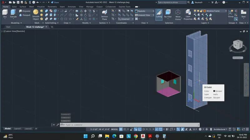
Step 6-
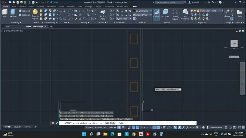
Step 7-
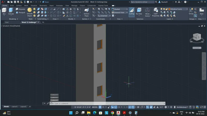
Step 8-
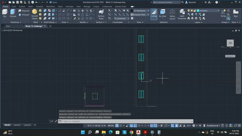
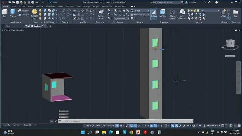
Final result-
Answer 3-
Aim- To create the ismoteric 3d view of a stair with railing as shown in the plan and elevation.
Step 1- Creating stairs as per given dimensions in 2d view.
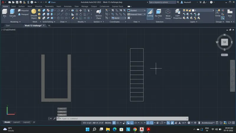
Step 2- Using Extrude options to give each stairs its desired height.
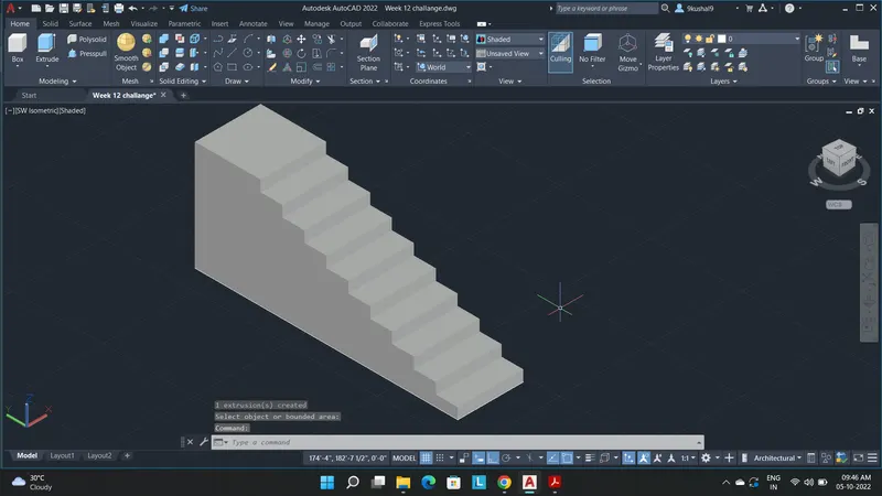
Step 3- Drawing inclined line to create waist slab as shoen in drawing.
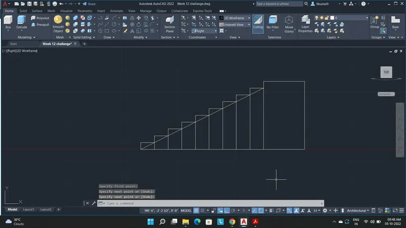
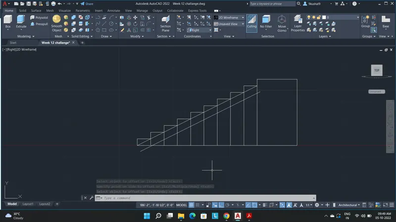
Step 4- Using Presspull option to create the shape of the steps
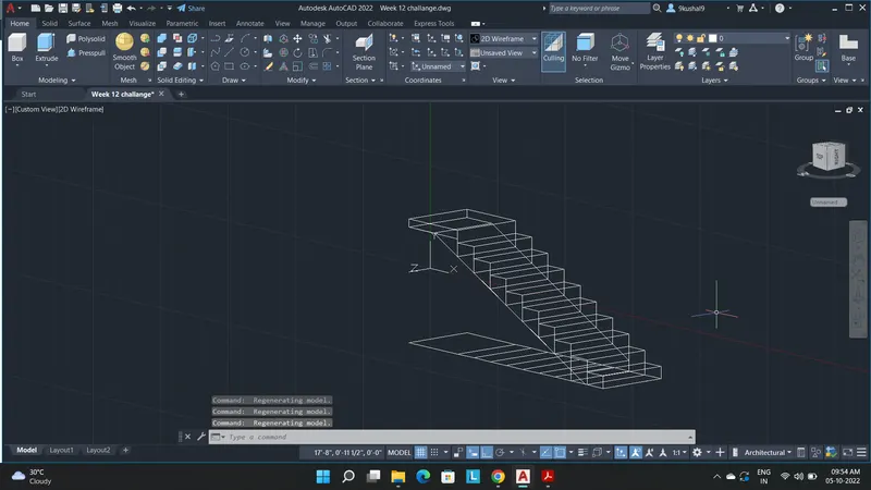
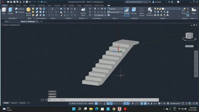
Step 5- Drawing circles for balustrades.
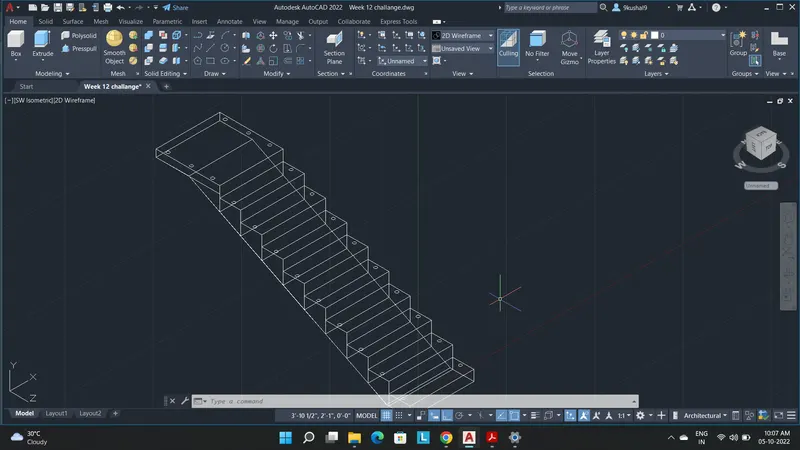
Step 6- Extuding the balustrades as per given dimension.
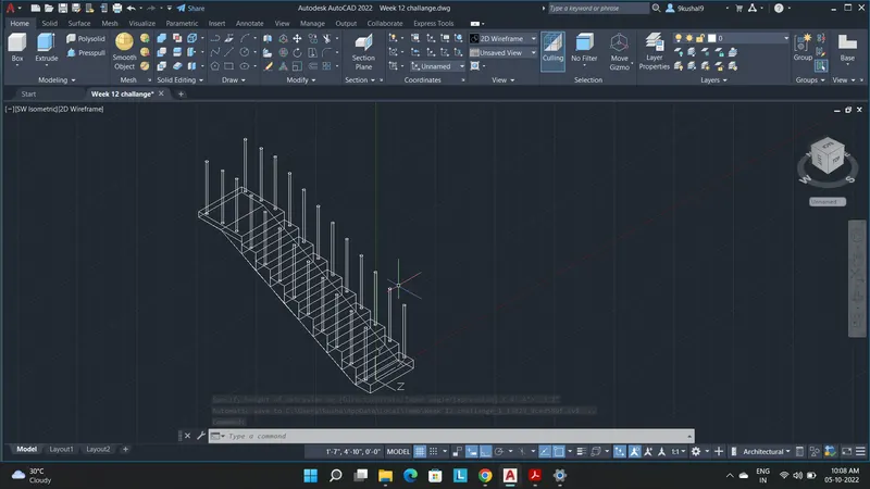
Step 7- Drwaing path for the handrails
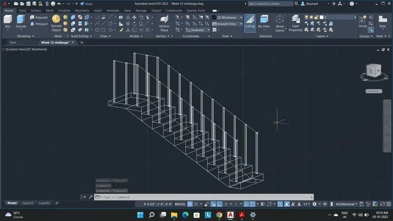
Step 8- Exruding the handrails circle aling the path drawn.
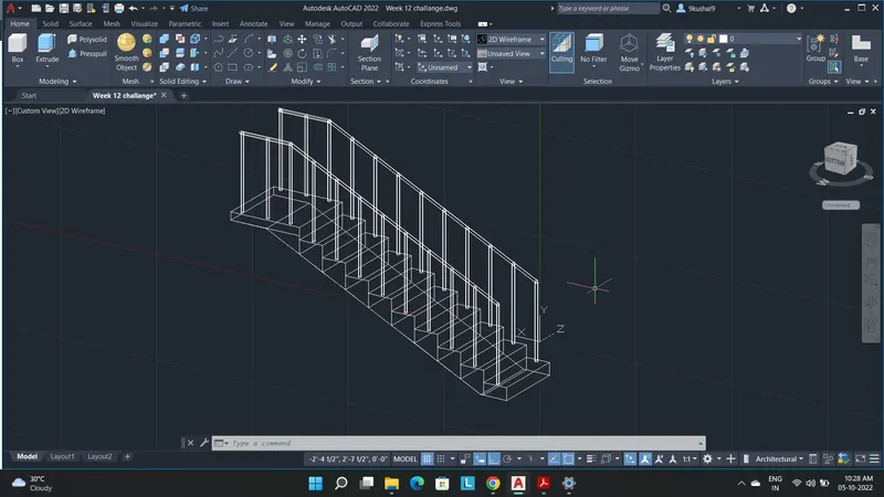
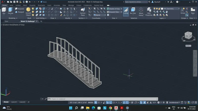
Final Result- Below is the completed staircase in 3d view.
Answer 4-
Aim- Create the 3D view of a Wall with spread footing . Create the Door opening only. Assume the size of the parpaet and the coping. See the plans and elevation for the details. Also, create a rendered view of the model with materials as of your choice.
Step 1- Drawing the wall as per given plan.
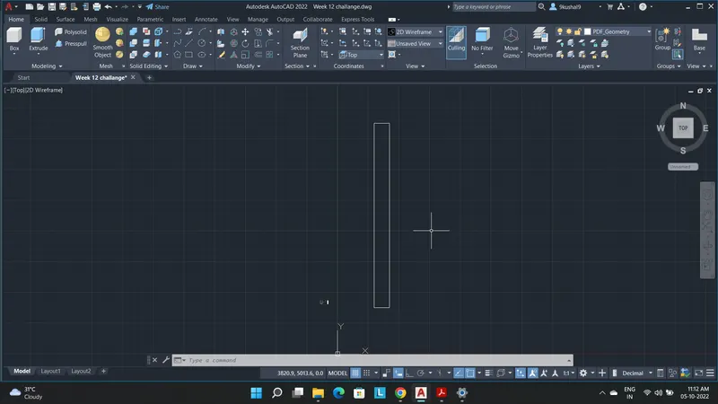
Creating the footings.
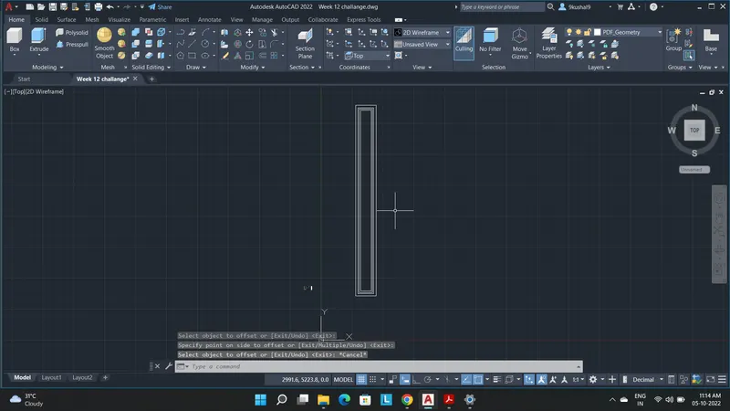
Step 2- Extruding the footings and PCC
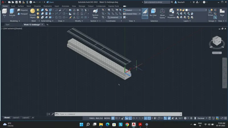
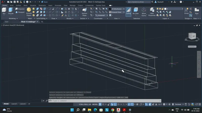
Step 3- Marking the door opening
Step 4- Making a cutout of door.
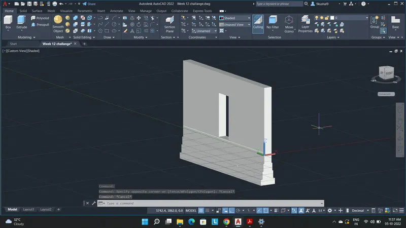
Step 5- Making a chajja
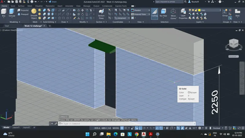
Step 6- Assigning different materials and rendering the drawing.
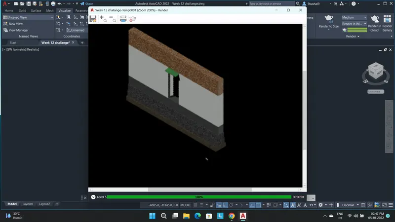
Final result- Below attached image shows the final result of the drawing. Also please find the attached autocad drawing file for your reference.