Creating 3D Isometric view of various structural elements in AutoCAD
1Q:
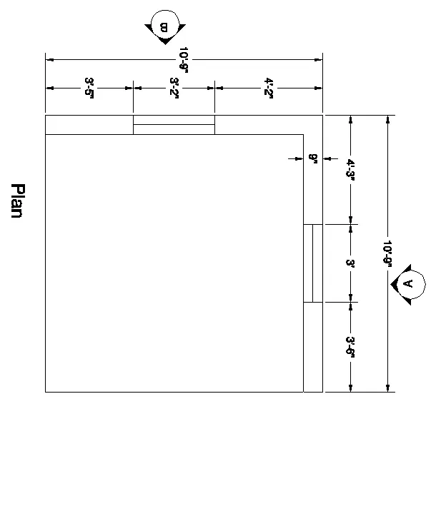
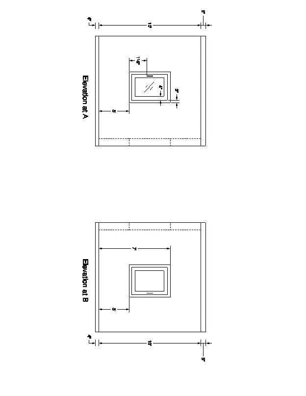
AIM:Create a 3D Isometric View of the building with plan and elevation given.
PROCEDURE:
Type UN and press enter
Under Drawing Units, select Engineering
Now the lower limit is set to 0', 0' and upper limit to 50', 50'
Type Z enter to zoom and A enter to all.
Now in the layer properties crate different layers for the DRAWING.
Now in settings selecting 3D Modelling and visual style control to 2D wireframe.
By using the Line commands Draw the PLAN, Elevation at A, Elevation at B, as shown in the picture.
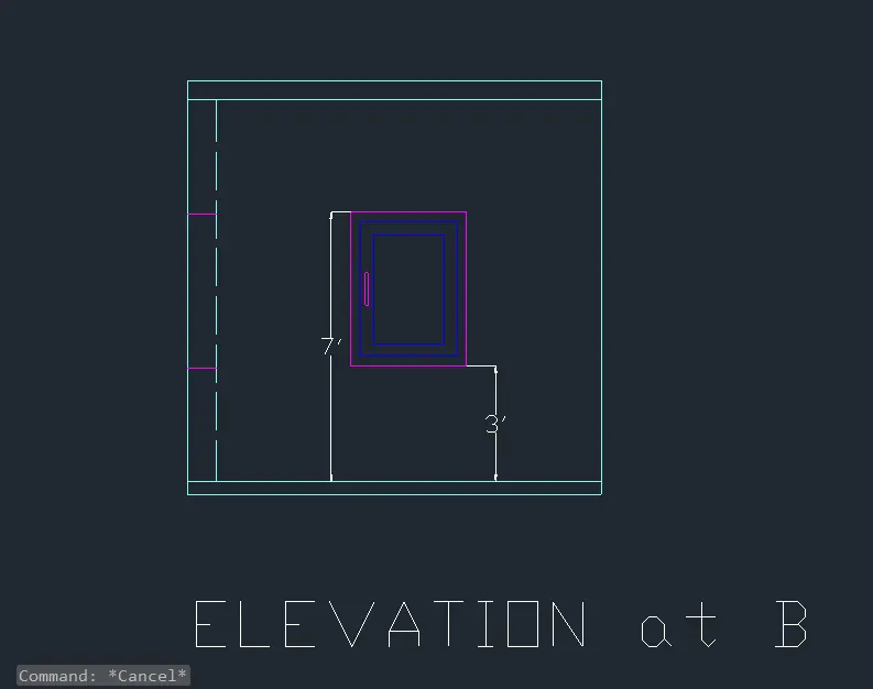
Now At the plan select the BOUNDRY and crate the REGION in the plan for side walls.
Now using the EXTRUDE command EXTRUE the wall as 4" as floor level,10' as interior wall, 6"as SLAB.
Also EXTRUDE the window wall at 10'10" and by UNION command merge it.
Now create the rectanle by using REC command at the window and create the region by REGION commmand ,move it in the 3'4"from the plan.
Now EXTRUDE it at the height of 4', and SUBTACT it fron the wall as shown in below.
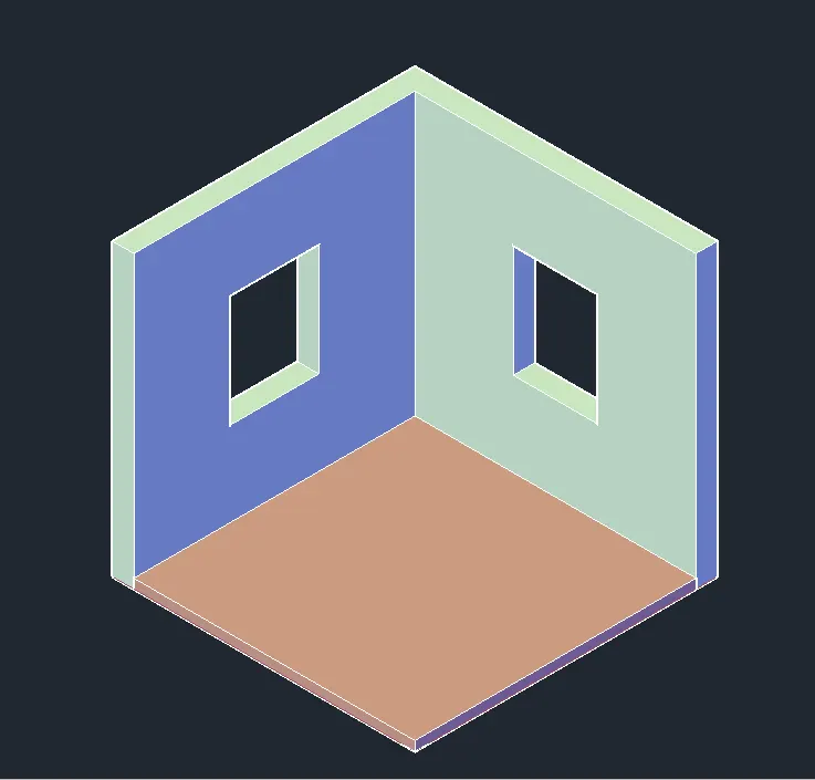
Now draw the TWO RECTANGLE by REC command 3'2"x4'.&3'x4'
Now using the OFFSET COMMAND offset it 3"and 4" inner to inner.
Now make it region and EXTRUDE it at 3" and inner frame as 2" and glass as 1".
Now subtract it from the frame as shown below.
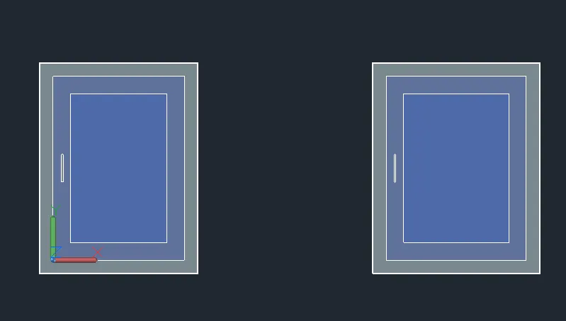
Now using the 3DROTATE command and 3DMOVE command Place the window in the plan.
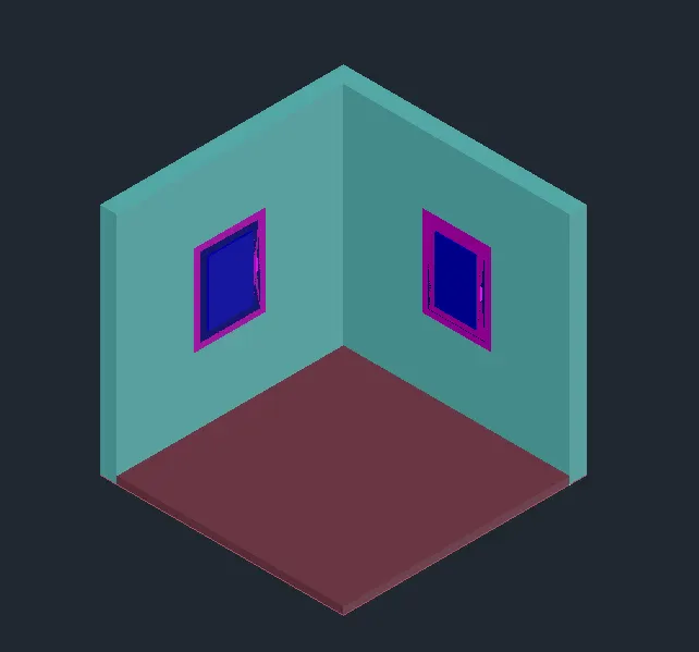
RESULT:Created a 3D Isometric View of the building with plan and elevation as given.
2Q:
AIM:Create the 3D View of the Building Façade as given in the plan and elevation. Also, see the detail of the window.
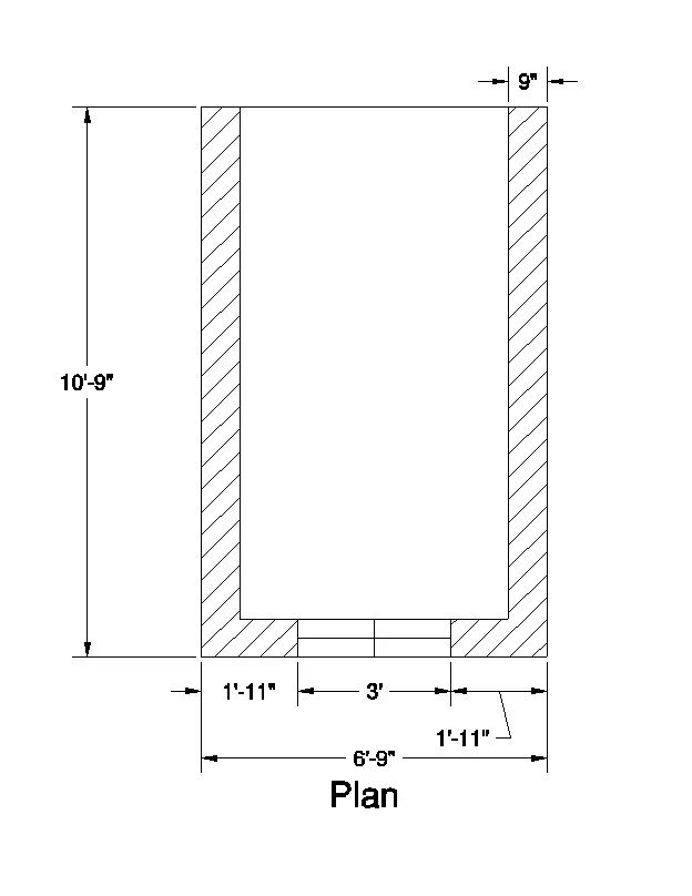
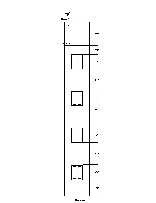
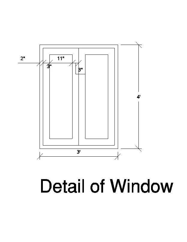
PROCEDURE:
Type UN and press enter
Under Drawing Units, select Engineering
Now the lower limit is set to 0', 0' and upper limit to 50', 50'
Type Z enter to zoom and A enter to all.
Now in the layer properties crate different layers for the DRAWING.
Now in settings selecting 3D Modelling and visual style control to 2D wireframe.
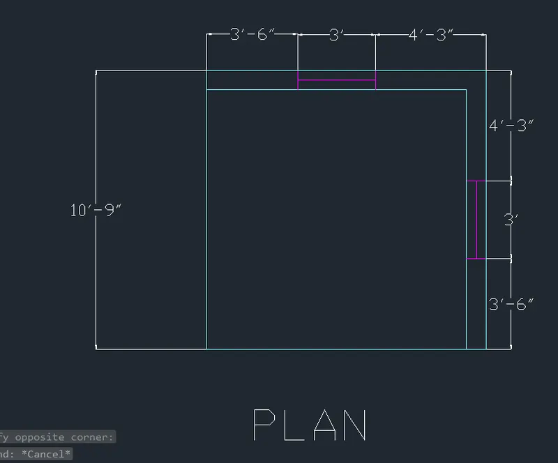
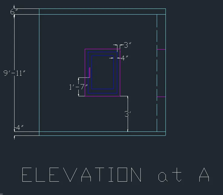
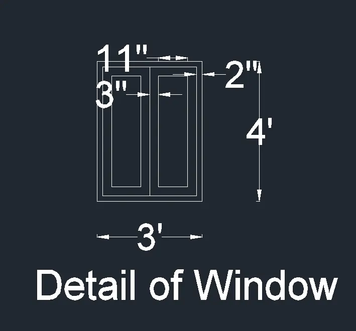
By using the Line commands Draw the PLAN, Elevation, Detail of Window as shown in the picture.
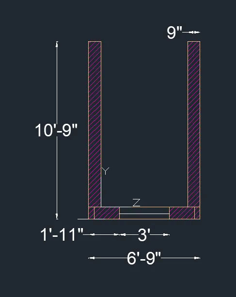
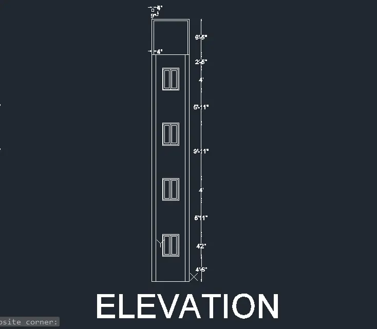
Now At the plan select the BOUNDRY and crate the REGION in the plan for side walls.
Now using the EXTRUDE command EXTRUE the wall as 10'
Also EXTRUDE the window wall at 10' and by UNION command merge it.
Now create the rectanle by using REC command at the window and create the region by REGION commmand ,move it in the 4'6"from the plan.
Now EXTRUDE it at the height of 4'2"', and SUBTACT it fron the wall as shown in below.
Now Do the for remaing part of the Elevation AS shown below
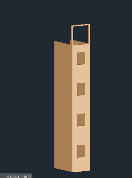
Now draw the TWO RECTANGLE by REC command 3'x4'.&3'x4'2"
Now using the OFFSET COMMAND offset it 3"and 4" inner to inner.
Now make it region and EXTRUDE it at 3" and inner frame as 2" and glass as 1".
Now subtract it from the frame as shown below.
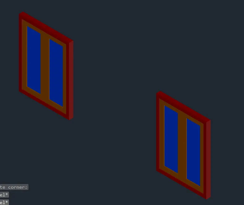
Now using the 3DROTATE command and 3DMOVE command Place the window in the plan.
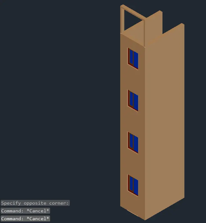
RESULT:Created the 3D View of the Building Façade as given in the plan and elevation. Also the detail of the window.
3Q:
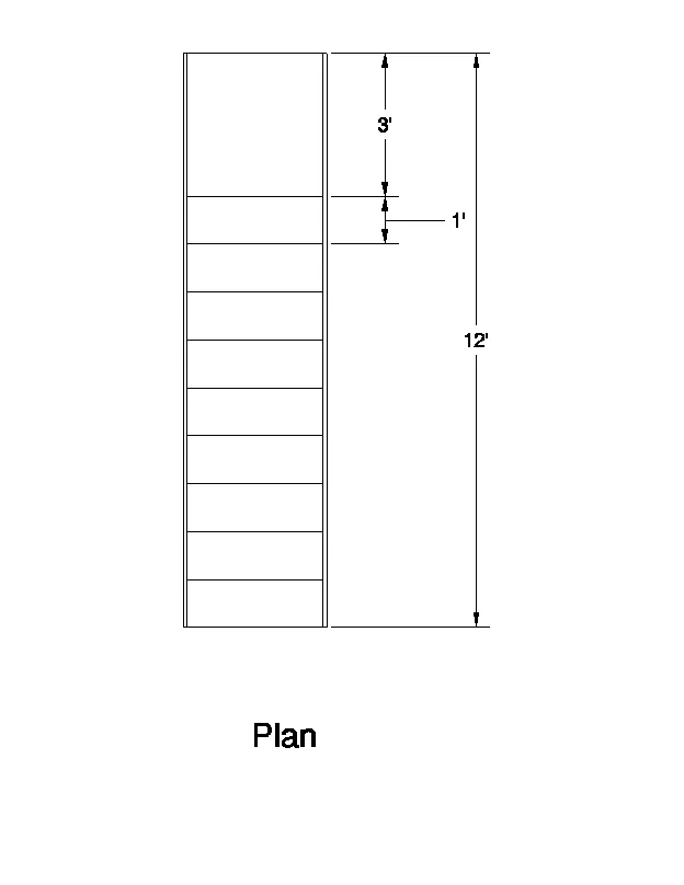
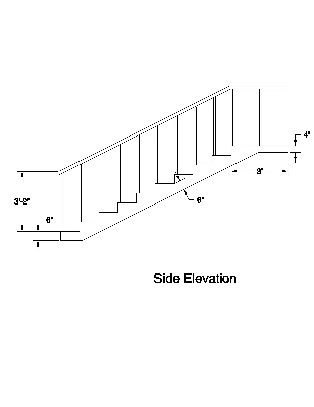
AIM:Create the ismoteric 3d view of a stair with railing as shown in the plan and elevation. Assume the size of the balustrades and the hand rails.
PROCEDURE:
Type UN and press enter
Under Drawing Units, select Engineering
Now the lower limit is set to 0', 0' and upper limit to 50', 50'
Type Z enter to zoom and A enter to all.
Now in the layer properties crate different layers for the DRAWING.
Now in settings selecting 3D Modelling and visual style control to 2D wireframe.
By using the Line commands Draw the PLAN, S ide Elevation, as shown in the picture.
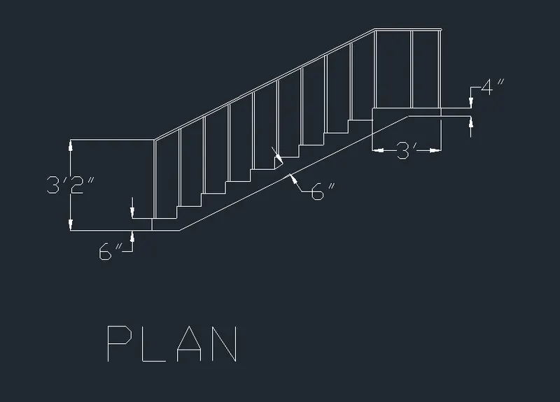
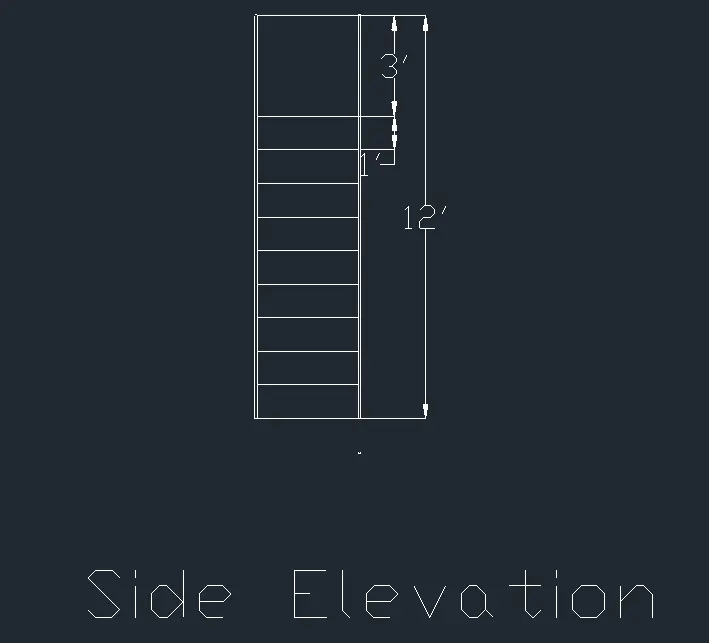
Now At the plan select the BOUNDRY and crate the REGION in the plan for stairs.
Now using the EXTRUDE command EXTRUE the stairs as 3' as shown.
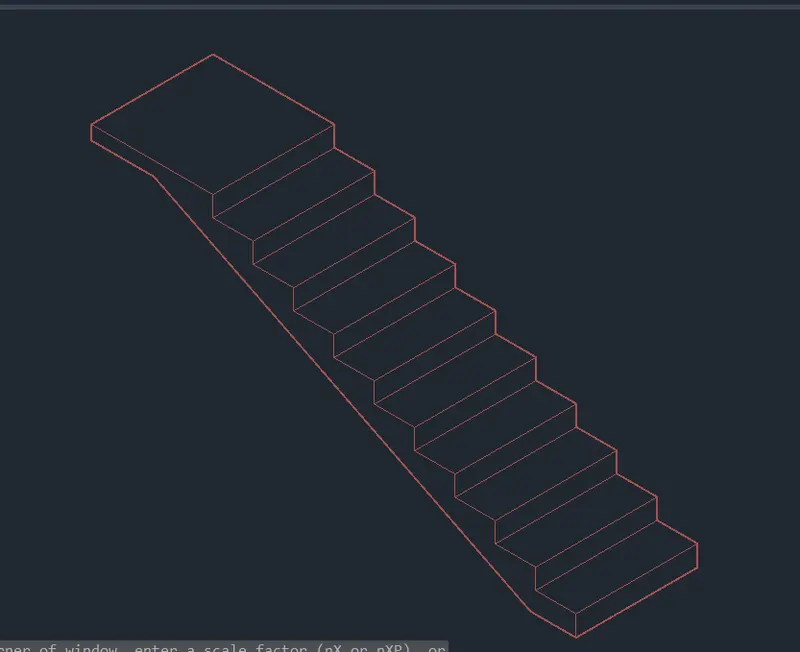
Now draw the circle 2" dia at the stairs for support rods.
Now crate the region and extrude the circle 3' height,Now copy the same for both sides for each step.
Now using the 3DPOLY draw the polyline for each support.
Now draw a circle 1" dia and Now using SEWEEP command Select the circle and choce the path as shown in below.
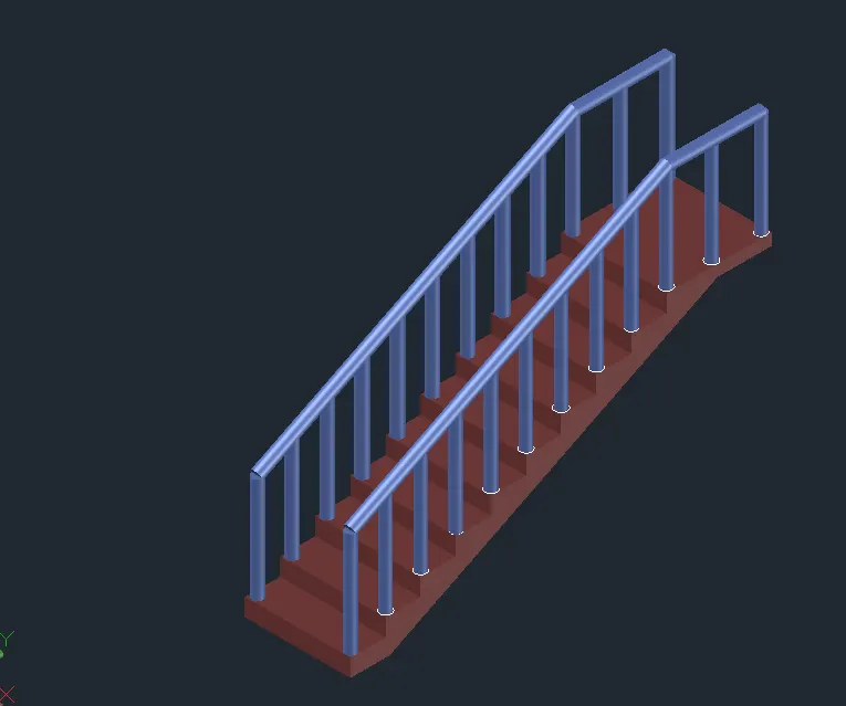
RESULT:Created the ismoteric 3d view of a stair with railing as shown in the plan and elevation. Assumed the size of the balustrades and the hand rails.
4Q:
AIM:Create the 3D view of a Wall with spread footing . Create the Door opening only. Assume the size of the parpaet and the coping. See the plans and elevation for the details. Also, create a rendered view of the model with materials as of your choice.
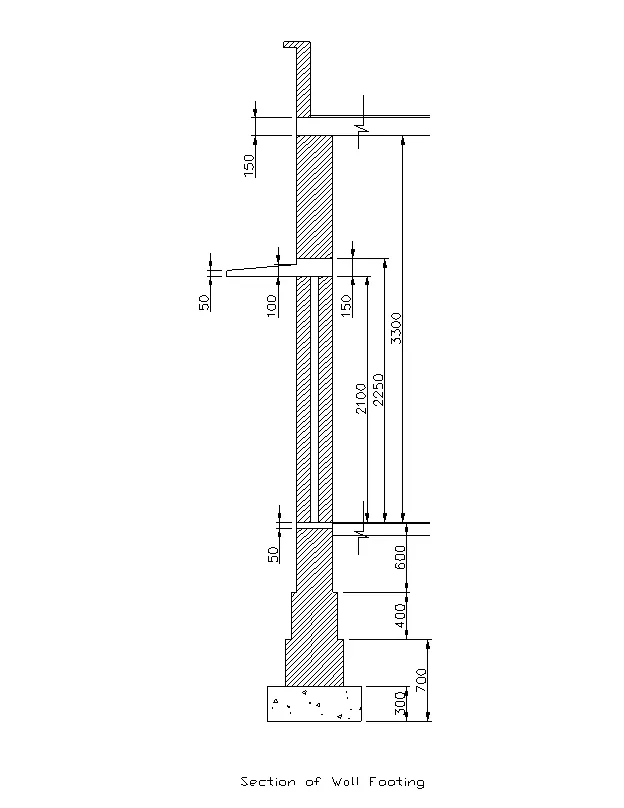
PROCEDURE:
Type UN and press enter
Under Drawing Units, select Engineering
Now the lower limit is set to 0, 0 and upper limit to 1000,1000
Type Z enter to zoom and A enter to all.
Now in the layer properties crate different layers for the DRAWING.
Now in settings selecting 3D Modelling and visual style control to 2D wireframe.
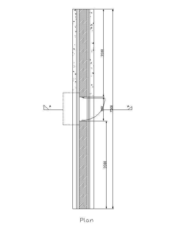
By using the Line commands Draw the PLAN, Section of wall footing, as shown in the picture.
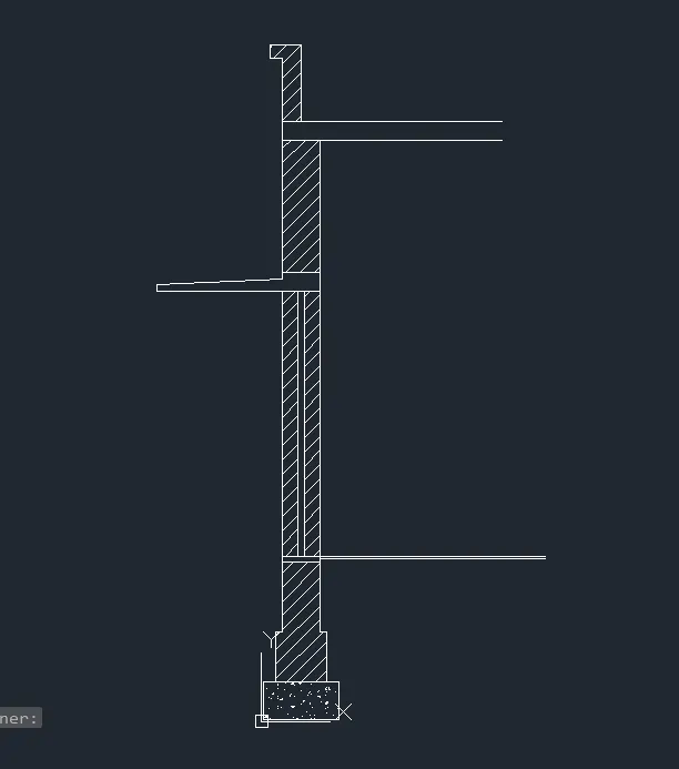
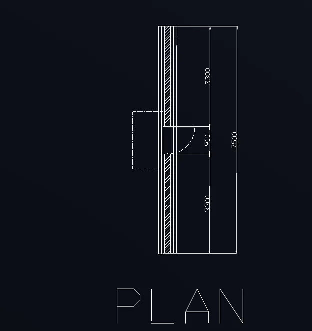
Now select the region for different portion of the footing and wall.
Now EXTRUDE the footing portion by 7500mm, Do the same for remaining portions of the wall.
Now create the rectanle by using REC command at the wall and create the region by REGION commmand.
Now EXTRUDE it at the height of 2100, and SUBTACT it fron the wall as shown in below.
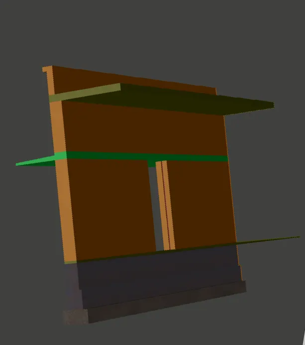
Now in Visualize select the Material required for the drawing.
Select the Material type i.e, concrete and select the footing and ASSIGN the selection for footing,same for Door frame,footing.
Now RENDER using RR command and save the file.
RESULT:Created the 3D view of a Wall with spread footing using rendering.